steering wheel FIAT 500X 2018 Owner handbook (in English)
[x] Cancel search | Manufacturer: FIAT, Model Year: 2018, Model line: 500X, Model: FIAT 500X 2018Pages: 276, PDF Size: 7.08 MB
Page 125 of 276
The reachable positions are + (higher
gear) or - (lower gear). These positions
are unstable: the lever always returns to
central position.
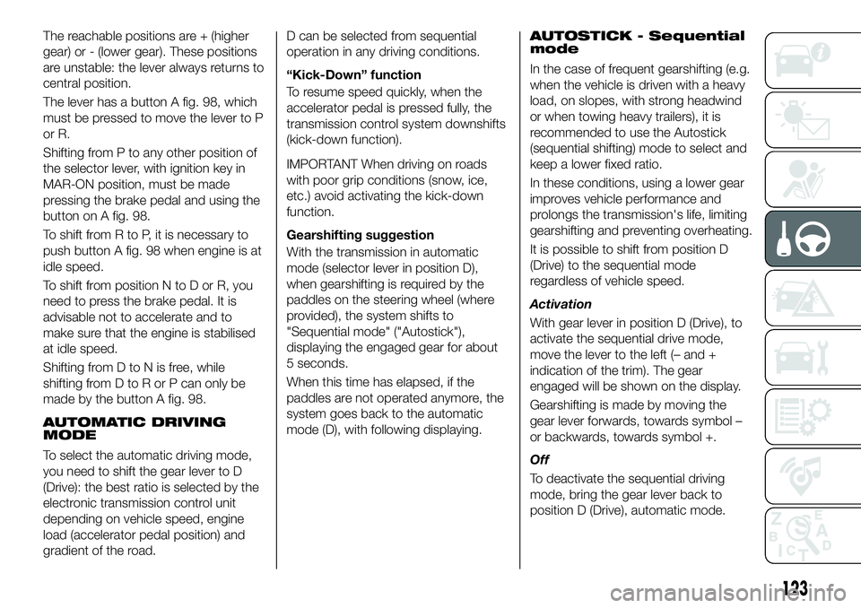
The lever has a button A fig. 98, which
must be pressed to move the lever to P
or R.
Shifting from P to any other position of
the selector lever, with ignition key in
MAR-ON position, must be made
pressing the brake pedal and using the
button on A fig. 98.
To shift from R to P, it is necessary to
push button A fig. 98 when engine is at
idle speed.
To shift from position N to D or R, you
need to press the brake pedal. It is
advisable not to accelerate and to
make sure that the engine is stabilised
at idle speed.
Shifting from D to N is free, while
shifting from D to R or P can only be
made by the button A fig. 98.
AUTOMATIC DRIVING
MODE
To select the automatic driving mode,
you need to shift the gear lever to D
(Drive): the best ratio is selected by the
electronic transmission control unit
depending on vehicle speed, engine
load (accelerator pedal position) and
gradient of the road.D can be selected from sequential
operation in any driving conditions.
“Kick-Down” function
To resume speed quickly, when the
accelerator pedal is pressed fully, the
transmission control system downshifts
(kick-down function).
IMPORTANT When driving on roads
with poor grip conditions (snow, ice,
etc.) avoid activating the kick-down
function.
Gearshifting suggestion
With the transmission in automatic
mode (selector lever in position D),
when gearshifting is required by the
paddles on the steering wheel (where
provided), the system shifts to
"Sequential mode" ("Autostick"),
displaying the engaged gear for about
5 seconds.
When this time has elapsed, if the
paddles are not operated anymore, the
system goes back to the automatic
mode (D), with following displaying.
AUTOSTICK - Sequential
mode
In the case of frequent gearshifting (e.g.
when the vehicle is driven with a heavy
load, on slopes, with strong headwind
or when towing heavy trailers), it is
recommended to use the Autostick
(sequential shifting) mode to select and
keep a lower fixed ratio.
In these conditions, using a lower gear
improves vehicle performance and
prolongs the transmission's life, limiting
gearshifting and preventing overheating.
It is possible to shift from position D
(Drive) to the sequential mode
regardless of vehicle speed.
Activation
With gear lever in position D (Drive), to
activate the sequential drive mode,
move the lever to the left (– and +
indication of the trim). The gear
engaged will be shown on the display.
Gearshifting is made by moving the
gear lever forwards, towards symbol –
or backwards, towards symbol +.
Off
To deactivate the sequential driving
mode, bring the gear lever back to
position D (Drive), automatic mode.
123
Page 126 of 276
STEERING WHEEL
CONTROLS
(where provided)
56)
On some versions, the steering wheel
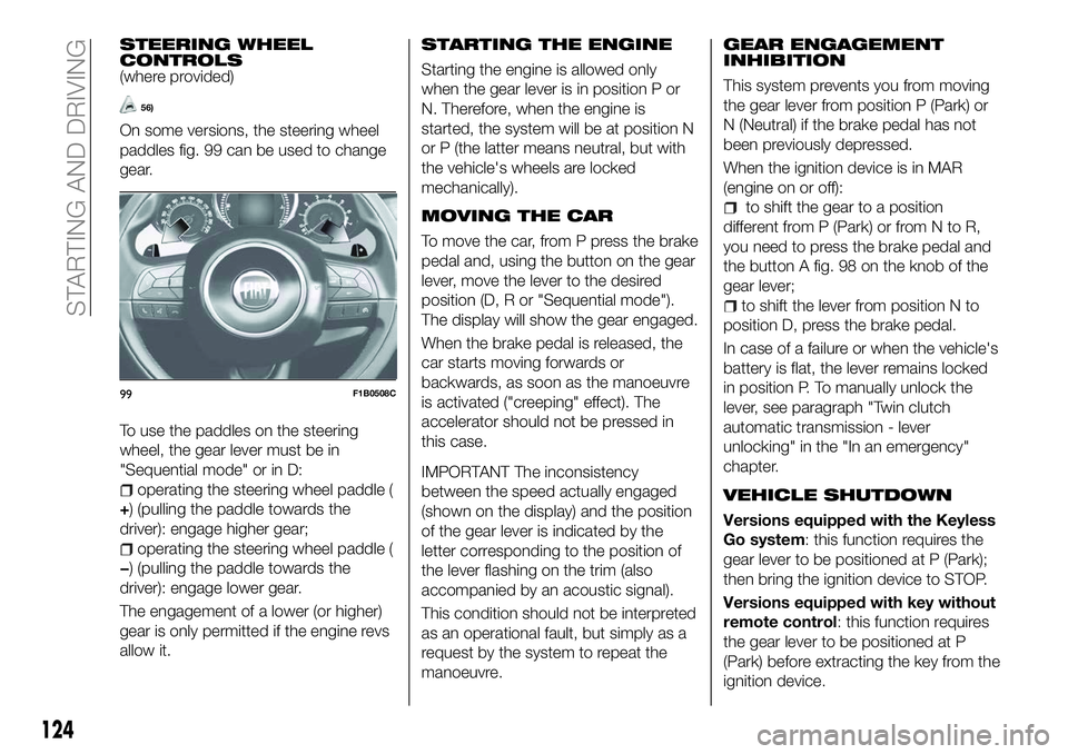
paddles fig. 99 can be used to change
gear.
To use the paddles on the steering
wheel, the gear lever must be in
"Sequential mode" or in D:
operating the steering wheel paddle (
+) (pulling the paddle towards the
driver): engage higher gear;
operating the steering wheel paddle (
−) (pulling the paddle towards the
driver): engage lower gear.
The engagement of a lower (or higher)
gear is only permitted if the engine revs
allow it.
STARTING THE ENGINE
Starting the engine is allowed only
when the gear lever is in position P or
N. Therefore, when the engine is
started, the system will be at position N
or P (the latter means neutral, but with
the vehicle's wheels are locked
mechanically).
MOVING THE CAR
To move the car, from P press the brake
pedal and, using the button on the gear
lever, move the lever to the desired
position (D, R or "Sequential mode").
The display will show the gear engaged.
When the brake pedal is released, the
car starts moving forwards or
backwards, as soon as the manoeuvre
is activated ("creeping" effect). The
accelerator should not be pressed in
this case.
IMPORTANT The inconsistency
between the speed actually engaged
(shown on the display) and the position
of the gear lever is indicated by the
letter corresponding to the position of
the lever flashing on the trim (also
accompanied by an acoustic signal).
This condition should not be interpreted
as an operational fault, but simply as a
request by the system to repeat the
manoeuvre.
GEAR ENGAGEMENT
INHIBITION
This system prevents you from moving
the gear lever from position P (Park) or
N (Neutral) if the brake pedal has not
been previously depressed.
When the ignition device is in MAR
(engine on or off):
to shift the gear to a position
different from P (Park) or from N to R,
you need to press the brake pedal and
the button A fig. 98 on the knob of the
gear lever;
to shift the lever from position N to
position D, press the brake pedal.
In case of a failure or when the vehicle's
battery is flat, the lever remains locked
in position P. To manually unlock the
lever, see paragraph "Twin clutch
automatic transmission - lever
unlocking" in the "In an emergency"
chapter.
VEHICLE SHUTDOWN
Versions equipped with the Keyless
Go system: this function requires the
gear lever to be positioned at P (Park);
then bring the ignition device to STOP.
Versions equipped with key without
remote control: this function requires
the gear lever to be positioned at P
(Park) before extracting the key from the
ignition device.
99F1B0508C
124
STARTING AND DRIVING
Page 129 of 276
SPEED LIMITER
DESCRIPTION
This device allows the speed of the
vehicle to be limited to values which
can be set by the driver.
The maximum speed can be set both
with vehicle stationary and in motion.
The minimum speed that can be set is
30 km/h.
When the device is active, the vehicle
speed depends on the pressure at the
accelerator pedal, until the
programmed speed limit is reached
(see "Speed limit programming"
paragraph).
ACTIVATING THE DEVICE
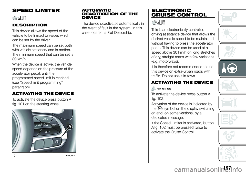
To activate the device press button A
fig. 101 on the steering wheel.
AUTOMATIC
DEACTIVATION OF THE
DEVICE
The device deactivates automatically in
the event of fault in the system. In this
case, contact a Fiat Dealership.
ELECTRONIC
CRUISE CONTROL
This is an electronically controlled
driving assistance device that allows the
desired vehicle speed to be maintained,
without having to press the accelerator
pedal. This device can be used at a
speed above 30 km/h on long stretches
of dry, straight roads with few variations
(e.g. motorways).
It is therefore not recommended to use
this device on extra-urban roads with
traffic. Do not use it in town.
ACTIVATING THE DEVICE
123) 124) 125)
To activate the device press button A
fig. 102.
Activation of the device is indicated by
the
symbol on the display switching
on and, on some versions, by a
dedicated message.
If the Speed Limiter is activated, button
Afig. 102 must be pressed twice to
activate the Cruise Control.
101F1B0141C
127
Page 131 of 276
ADAPTIVE CRUISE
CONTROL (ACC)
(where provided)
126) 127) 128) 129) 130) 131)
58) 59) 60) 61) 62) 63) 64)
DESCRIPTION
The Adaptive Cruise Control (ACC) is a
driver assist device which combines the
Cruise Control functions with one for
controlling the distance from the vehicle
ahead.
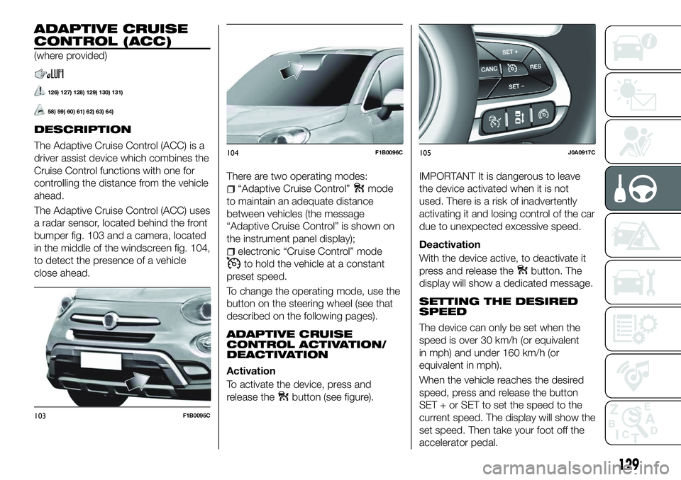
The Adaptive Cruise Control (ACC) uses
a radar sensor, located behind the front
bumper fig. 103 and a camera, located
in the middle of the windscreen fig. 104,
to detect the presence of a vehicle
close ahead.There are two operating modes:
“Adaptive Cruise Control”mode
to maintain an adequate distance
between vehicles (the message
“Adaptive Cruise Control” is shown on
the instrument panel display);
electronic “Cruise Control” mode
to hold the vehicle at a constant
preset speed.
To change the operating mode, use the
button on the steering wheel (see that
described on the following pages).
ADAPTIVE CRUISE
CONTROL ACTIVATION/
DEACTIVATION
Activation
To activate the device, press and
release the
button (see figure).
IMPORTANT It is dangerous to leave
the device activated when it is not
used. There is a risk of inadvertently
activating it and losing control of the car
due to unexpected excessive speed.
Deactivation
With the device active, to deactivate it
press and release the
button. The
display will show a dedicated message.
SETTING THE DESIRED
SPEED
The device can only be set when the
speed is over 30 km/h (or equivalent
in mph) and under 160 km/h (or
equivalent in mph).
When the vehicle reaches the desired
speed, press and release the button
SET + or SET to set the speed to the
current speed. The display will show the
set speed. Then take your foot off the
accelerator pedal.
103F1B0095C
104F1B0096C105J0A0917C
129
Page 139 of 276
WARNING
132)Parking and other potentially
dangerous manoeuvres are, however,
always the driver’s responsibility. When
performing these operations, always make
sure that there are no other people
(especially children) or animals on the route
you want to take. The parking sensors are
an aid for the driver, but the driver must
never allow their attention to lapse during
potentially dangerous manoeuvres, even
those executed at low speeds.
IMPORTANT
65) The sensors must be clean of mud,
dirt, snow or ice in order for the system to
operate correctly. Be careful not to scratch
or damage the sensors while cleaning
them. Avoid using dry, rough or hard
cloths. The sensors should be washed
using clean water with the addition of car
shampoo if necessary. When using special
washing equipment such as high pressure
jets or steam cleaning, clean the sensors
very quickly keeping the jet more than
10 cm away.
66) Have interventions on the bumper in
the area of the sensors carried out only by
a Fiat Dealership. Interventions on the
bumper that are not carried out properly
may compromise the operation of the
parking sensors. 67)
Only have the bumpers repainted or
any retouches to the paintwork in the area
of the sensors carried out by a Fiat
Dealership. Incorrect paint application
could affect the operation of the parking
sensors.
68) The sensors may provide a false
indication, interpreting the tow hook ball
assembly and the relevant attachment as
an obstacle in the area behind the vehicle.
LANE ASSIST
SYSTEM (lane
crossing warning)
DESCRIPTION
69) 70) 71) 72) 73) 74)
The Lane Assist system makes use of a
camera located on the windscreen to
detect the lane limits and calculate the
position of the vehicle within such limits,
in order to make sure that it remains
inside the lane.
When both limits of the lane are
detected and the vehicle crosses one of
them without the awareness of the
driver (direction indicator off), the Lane
Assist system provides a tactile warning
by applying torque to the steering wheel
(vibration), thus advising the driver that
he must take an action to remain in the
lane.
IMPORTANT The torque applied to the
steering wheel by the system is
sufficient for the driver to notice it, but
always limited, so that they can easily
override it, and the driver always
maintains control of the vehicle. The
driver can therefore turn the steering
wheel as required at all times.
137
Page 140 of 276
If the vehicle continues going beyond
the line of the lane without any
intervention from the driver, the
warning light (or the icon on the
display) will be displayed on the
instrument panel to urge the driver to
bring the vehicle back into the limits of
the lane.
IMPORTANT The system monitors the
presence of the driver's hands on the
steering wheel. If they are not detected,
the system emits an acoustic signal and
deactivates until it is reactivated by
pressing the dedicated button (see
description below).
When one limit of the lane is detected
and the vehicle crosses it (direction
indicator off), warning light
(or the
icon on the display) will be displayed on
the instrument panel to urge the driver
to bring the vehicle back into the lane.
In this case, the tactile warning
(vibration on the steering wheel) is not
provided.
SYSTEM ACT_IVATION/
DEACTIVATION
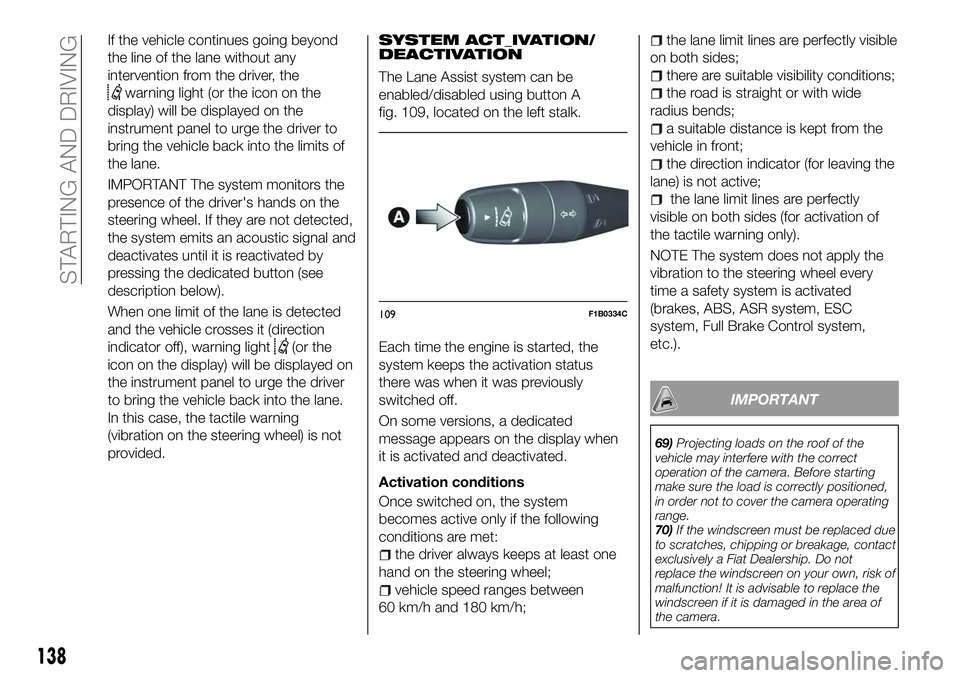
The Lane Assist system can be
enabled/disabled using button A
fig. 109, located on the left stalk.
Each time the engine is started, the
system keeps the activation status
there was when it was previously
switched off.
On some versions, a dedicated
message appears on the display when
it is activated and deactivated.
Activation conditions
Once switched on, the system
becomes active only if the following
conditions are met:
the driver always keeps at least one
hand on the steering wheel;
vehicle speed ranges between
60 km/h and 180 km/h;
the lane limit lines are perfectly visible
on both sides;
there are suitable visibility conditions;
the road is straight or with wide
radius bends;
a suitable distance is kept from the
vehicle in front;
the direction indicator (for leaving the
lane) is not active;
the lane limit lines are perfectly
visible on both sides (for activation of
the tactile warning only).
NOTE The system does not apply the
vibration to the steering wheel every
time a safety system is activated
(brakes, ABS, ASR system, ESC
system, Full Brake Control system,
etc.).
IMPORTANT
69) Projecting loads on the roof of the
vehicle may interfere with the correct
operation of the camera. Before starting
make sure the load is correctly positioned,
in order not to cover the camera operating
range.
70) If the windscreen must be replaced due
to scratches, chipping or breakage, contact
exclusively a Fiat Dealership. Do not
replace the windscreen on your own, risk of
malfunction! It is advisable to replace the
windscreen if it is damaged in the area of
the camera.
109F1B0334C
138
STARTING AND DRIVING
Page 164 of 276
When the operation is completed, lower
the luggage compartment mat and
position the punctured tyre on top of it,
ensuring that it is locked correctly so
that it doesn’t move during driving.
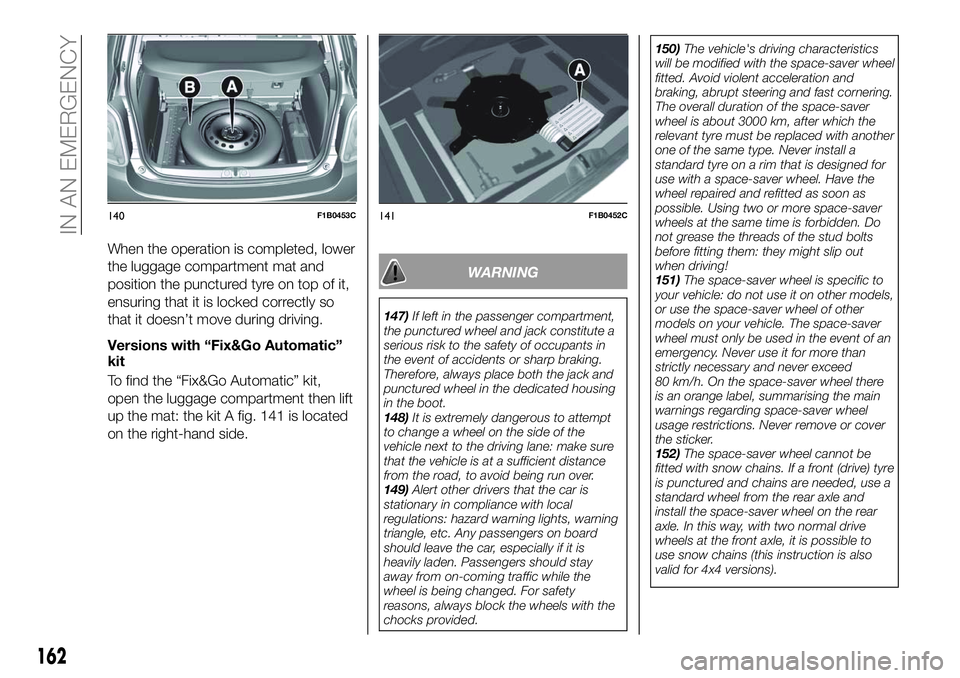
Versions with “Fix&Go Automatic”
kit
To find the “Fix&Go Automatic” kit,
open the luggage compartment then lift
up the mat: the kit A fig. 141 is located
on the right-hand side.
WARNING
147)If left in the passenger compartment,
the punctured wheel and jack constitute a
serious risk to the safety of occupants in
the event of accidents or sharp braking.
Therefore, always place both the jack and
punctured wheel in the dedicated housing
in the boot.
148) It is extremely dangerous to attempt
to change a wheel on the side of the
vehicle next to the driving lane: make sure
that the vehicle is at a sufficient distance
from the road, to avoid being run over.
149) Alert other drivers that the car is
stationary in compliance with local
regulations: hazard warning lights, warning
triangle, etc. Any passengers on board
should leave the car, especially if it is
heavily laden. Passengers should stay
away from on-coming traffic while the
wheel is being changed. For safety
reasons, always block the wheels with the
chocks provided. 150)
The vehicle's driving characteristics
will be modified with the space-saver wheel
fitted. Avoid violent acceleration and
braking, abrupt steering and fast cornering.
The overall duration of the space-saver
wheel is about 3000 km, after which the
relevant tyre must be replaced with another
one of the same type. Never install a
standard tyre on a rim that is designed for
use with a space-saver wheel. Have the
wheel repaired and refitted as soon as
possible. Using two or more space-saver
wheels at the same time is forbidden. Do
not grease the threads of the stud bolts
before fitting them: they might slip out
when driving!
151) The space-saver wheel is specific to
your vehicle: do not use it on other models,
or use the space-saver wheel of other
models on your vehicle. The space-saver
wheel must only be used in the event of an
emergency. Never use it for more than
strictly necessary and never exceed
80 km/h. On the space-saver wheel there
is an orange label, summarising the main
warnings regarding space-saver wheel
usage restrictions. Never remove or cover
the sticker.
152) The space-saver wheel cannot be
fitted with snow chains. If a front (drive) tyre
is punctured and chains are needed, use a
standard wheel from the rear axle and
install the space-saver wheel on the rear
axle. In this way, with two normal drive
wheels at the front axle, it is possible to
use snow chains (this instruction is also
valid for 4x4 versions).
140F1B0453C141F1B0452C
162
IN AN EMERGENCY
Page 171 of 276
fully depress the brake pedal and
hold it down;
insert the screwdriver supplied
perpendicularly in hole B fig. 151 and
adjust the release lever;
place the gear lever in N (Neutral)
position;
refit the gear lever gaiter and trim
correctly;
start the engine.
AUTOMATIC
TRANSMISSION -
KEY REMOVAL
83)
The ignition key (for versions with key
without remote control) can be removed
only if the gear lever is in position P
(Park).
If the vehicle battery is flat and the
ignition key is engaged, the latter is
locked in position.
To remove the key manually, proceed
as follows:
stop the vehicle in safety conditions,
engage a gear and the electric parking
brake;
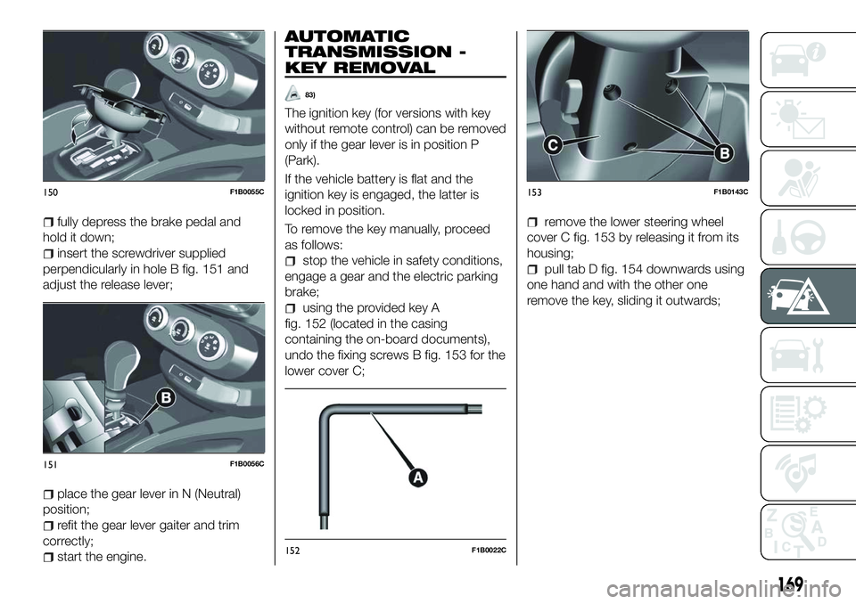
using the provided key A
fig. 152 (located in the casing
containing the on-board documents),
undo the fixing screws B fig. 153 for the
lower cover C;
remove the lower steering wheel
cover C fig. 153 by releasing it from its
housing;
pull tab D fig. 154 downwards using
one hand and with the other one
remove the key, sliding it outwards;
150F1B0055C
151F1B0056C
152F1B0022C
153F1B0143C
169
Page 173 of 276
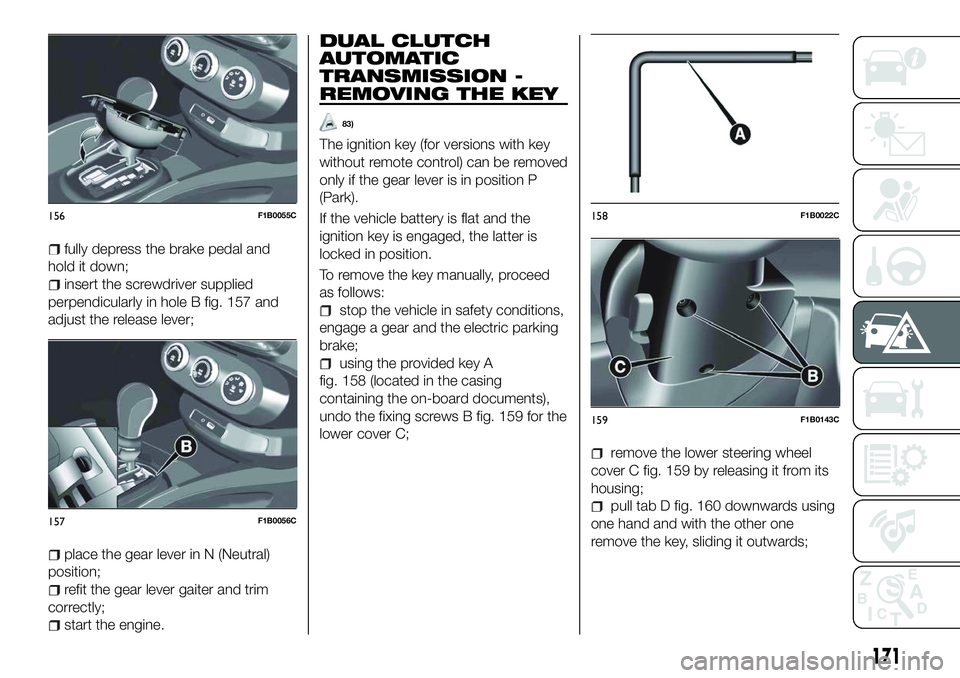
fully depress the brake pedal and
hold it down;
insert the screwdriver supplied
perpendicularly in hole B fig. 157 and
adjust the release lever;
place the gear lever in N (Neutral)
position;
refit the gear lever gaiter and trim
correctly;
start the engine.
DUAL CLUTCH
AUTOMATIC
TRANSMISSION -
REMOVING THE KEY
83)
The ignition key (for versions with key
without remote control) can be removed
only if the gear lever is in position P
(Park).
If the vehicle battery is flat and the
ignition key is engaged, the latter is
locked in position.
To remove the key manually, proceed
as follows:
stop the vehicle in safety conditions,
engage a gear and the electric parking
brake;
using the provided key A
fig. 158 (located in the casing
containing the on-board documents),
undo the fixing screws B fig. 159 for the
lower cover C;
remove the lower steering wheel
cover C fig. 159 by releasing it from its
housing;
pull tab D fig. 160 downwards using
one hand and with the other one
remove the key, sliding it outwards;
156F1B0055C
157F1B0056C
158F1B0022C
159F1B0143C
171
Page 175 of 276
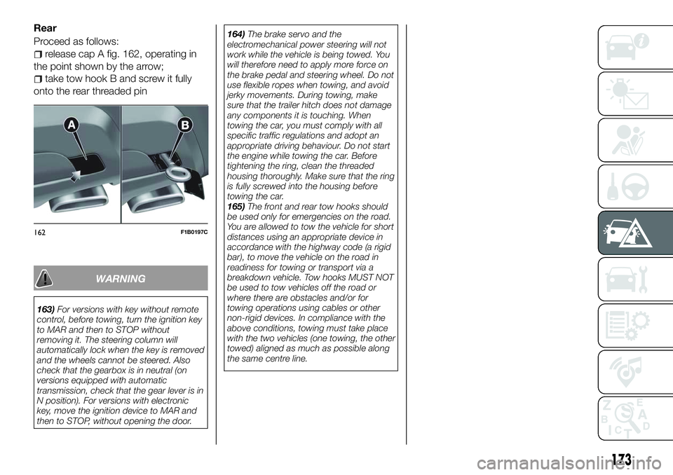
Rear
Proceed as follows:
release cap A fig. 162, operating in
the point shown by the arrow;
take tow hook B and screw it fully
onto the rear threaded pin
WARNING
163) For versions with key without remote
control, before towing, turn the ignition key
to MAR and then to STOP without
removing it. The steering column will
automatically lock when the key is removed
and the wheels cannot be steered. Also
check that the gearbox is in neutral (on
versions equipped with automatic
transmission, check that the gear lever is in
N position). For versions with electronic
key, move the ignition device to MAR and
then to STOP, without opening the door. 164)
The brake servo and the
electromechanical power steering will not
work while the vehicle is being towed. You
will therefore need to apply more force on
the brake pedal and steering wheel. Do not
use flexible ropes when towing, and avoid
jerky movements. During towing, make
sure that the trailer hitch does not damage
any components it is touching. When
towing the car, you must comply with all
specific traffic regulations and adopt an
appropriate driving behaviour. Do not start
the engine while towing the car. Before
tightening the ring, clean the threaded
housing thoroughly. Make sure that the ring
is fully screwed into the housing before
towing the car.
165) The front and rear tow hooks should
be used only for emergencies on the road.
You are allowed to tow the vehicle for short
distances using an appropriate device in
accordance with the highway code (a rigid
bar), to move the vehicle on the road in
readiness for towing or transport via a
breakdown vehicle. Tow hooks MUST NOT
be used to tow vehicles off the road or
where there are obstacles and/or for
towing operations using cables or other
non-rigid devices. In compliance with the
above conditions, towing must take place
with the two vehicles (one towing, the other
towed) aligned as much as possible along
the same centre line.
162F1B0197C
173