door lock FIAT BARCHETTA 2003 1.G Owners Manual
[x] Cancel search | Manufacturer: FIAT, Model Year: 2003, Model line: BARCHETTA, Model: FIAT BARCHETTA 2003 1.GPages: 170, PDF Size: 3.55 MB
Page 12 of 170
11
fig. 4
P5S00624m
THE FIAT
CODE SYSTEM
To further protect your car from at-
tempted theft, it has been fitted with
an electronic engine immobiliser sys-
tem called Fiat CODE which is auto-
matically activated when the ignition
key is removed. The ignition keys, in
fact, are fitted with an electronic de-
vice that transmits a coded signal to
the Fiat CODE unit: only if this signal
is recognised can the engine be start-
ed. The coded signal is the password
with which the control unit recognis-
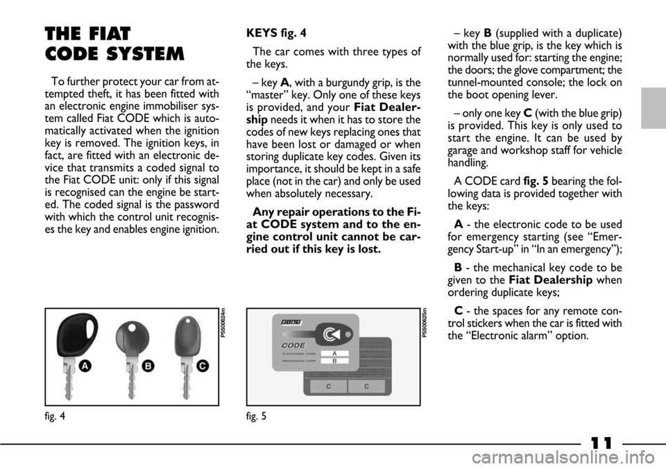
es the key and enables engine ignition. KEYS fig. 4
The car comes with three types of
the keys.
– key A, with a burgundy grip, is the
“master” key. Only one of these keys
is provided, and your Fiat Dealer-
ship needs it when it has to store the
codes of new keys replacing ones that
have been lost or damaged or when
storing duplicate key codes. Given its
importance, it should be kept in a safe
place (not in the car) and only be used
when absolutely necessary.
Any repair operations to the Fi-
at CODE system and to the en-
gine control unit cannot be car-
ried out if this key is lost.– key B(supplied with a duplicate)
with the blue grip, is the key which is
normally used for: starting the engine;
the doors; the glove compartment; the
tunnel-mounted console; the lock on
the boot opening lever.
– only one key C(with the blue grip)
is provided. This key is only used to
start the engine. It can be used by
garage and workshop staff for vehicle
handling.
A CODE card fig. 5bearing the fol-
lowing data is provided together with
the keys:
A- the electronic code to be used
for emergency starting (see “Emer-
gency Start-up” in “In an emergency”);
B- the mechanical key code to be
given to the Fiat Dealershipwhen
ordering duplicate keys;
C- the spaces for any remote con-
trol stickers when the car is fitted with
the “Electronic alarm” option.
fig. 5
P5S00625m
Page 14 of 170
13
DUPLICATING KEYS
If you ask for extra keys, remember
that all the keys, both the new ones
and those you already possess, must
be stored in the memory (up to a
maximum of 7). Go directly to your
nearest Fiat Dealership, taking with
you the key with the burgundy grip, all
the other keys in your possession and
the CODE card.
The codes of any keys that are not
available when the new storage pro-
cedure is carried out will be deleted
from the memory to prevent any lost
or stolen keys being used to start the
car.OPERATION
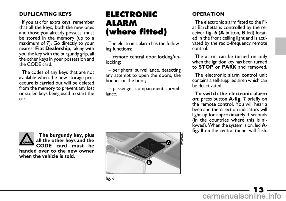
The electronic alarm fitted to the Fi-
at Barchetta is controlled by the re-
ceiver fig. 6(Abutton, Bled) locat-
ed in the front ceiling light and is acti-
vated by the radio-frequency remote
control.
The alarm can be turned on only
when the ignition key has been turned
toSTOPor PARKand removed.
The electronic alarm control unit
contains a self-supplied siren which can
be deactivated.
To switch the electronic alarm
on: press button A-fig. 7briefly on
the remote control. You will hear a
beep and the direction indicators will
light up for approximately 3 seconds
(in the countries where this is al-
lowed). When the system is on, led A-
fig. 8on the central tunnel will flash.ELECTRONIC
ALARM
(where fitted)
The electronic alarm has the follow-
ing functions:
– remote central door locking/un-
locking;
– peripheral surveillance, detecting
any attempt to open the doors, the
bonnet or the boot;
– passenger compartment surveil-
lance.
The burgundy key, plus
all the other keys and the
CODE card must be
handed over to the new owner
when the vehicle is sold.
fig. 6
P5S10002m
Page 17 of 170
The car alarm absorbs
electricity. If you plan on
not using the car for
more than a month, you are ad-
vised to switch the system off
with the remote control and to
turn the emergency key to the
“OFF” position.
16
WHEN THE ALARM
GOES OFF
When the car alarm is activated, the
electronic alarm will be set off if:
1)One of the doors, the bonnet or
the boot are opened.
2)The battery is disconnected or the
electronic alarm power supply cables
are cut.
3) When something enters the pas-
senger compartment.
4)The outside of the car is knocked.
5)The key is turned to MAR.
A siren sounds for approximately 26
seconds (for a maximum of 3 cycles
and 5-second pauses if the condition
persists) when the electronic alarm is
triggered. The direction indicators
flash (in countries where this is al-
lowed) for approximately 5 minutes.
Once the conditions cease, the sys-
tem will continue its normal surveil-
lance function.To stop the electronic alarm, press
the remote control button. If this does
not work, turn the alarm off by turn-
ing the emergency key toOFF(see
next paragraph “How to turn the
alarm”).
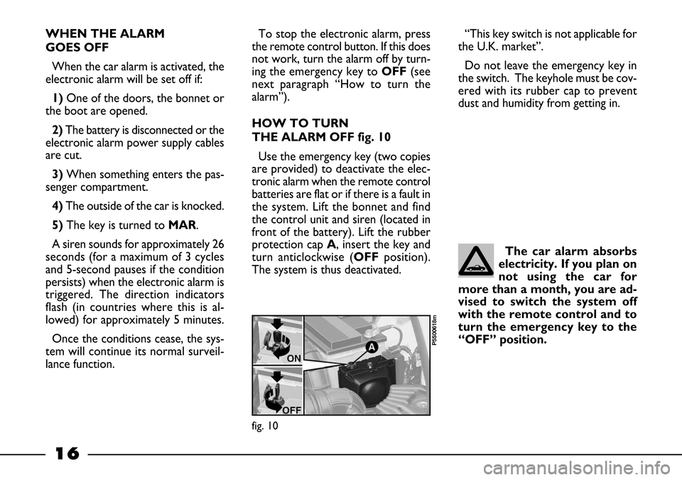
HOW TO TURN
THE ALARM OFF fig. 10
Use the emergency key (two copies
are provided) to deactivate the elec-
tronic alarm when the remote control
batteries are flat or if there is a fault in
the system. Lift the bonnet and find
the control unit and siren (located in
front of the battery). Lift the rubber
protection cap A, insert the key and
turn anticlockwise (OFFposition).
The system is thus deactivated.“This key switch is not applicable for
the U.K. market”.
Do not leave the emergency key in
the switch. The keyhole must be cov-
ered with its rubber cap to prevent
dust and humidity from getting in.
fig. 10
P5S00618m
Page 18 of 170
17
HOW TO KNOW IF
THE ALARM HAS GONE OFF
If the car alarm was triggered while
you were away, led A-fig. 8on the
central tunnel will flash to identify the
reason for it:
Light on: remote control battery
flat.
1 flash: right door.
2 flashes: left door.
5 flashes: passenger compartment
sensors (movement inside the pas-
senger compartment).6 flashes: bonnet.
7 flashes: boot.
8 flashes: ignition tampered with.
9 flashes: alarm power supply cables
cut.
10 flashes: at least three different
causes.
The led will go out when the ignition
key is turned toMARor after 2 min-
utes.IGNITION SWITCH
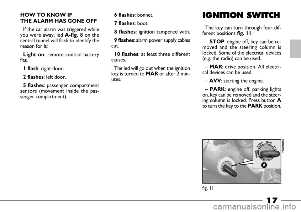
The key can turn through four dif-
ferent positions fig. 11:
– STOP: engine off, key can be re-
moved and the steering column is
locked. Some of the electrical devices
(e.g. the radio) can be used.
– MAR: drive position. All electri-
cal devices can be used.
– AVV: starting the engine.
– PARK: engine off, parking lights
on, key can be removed and the steer-
ing column is locked. Press button A
to turn the key to the PARKposition.
fig. 11
P5S00626m
Page 43 of 170
42
INTERIOR
EQUIPMENT
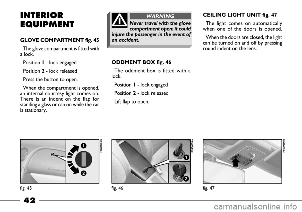
GLOVE COMPARTMENT fig. 45
The glove compartment is fitted with
a lock.
Position1- lock engaged
Position2- lock released
Press the button to open.
When the compartment is opened,
an internal courtesy light comes on.
There is an indent on the flap for
standing a glass or can on while the car
is stationary.ODDMENT BOX fig. 46
The oddment box is fitted with a
lock.
Position 1- lock engaged
Position 2- lock released
Lift flap to open. CEILING LIGHT UNIT fig. 47
The light comes on automatically
when one of the doors is opened.
When the doors are closed, the light
can be turned on and off by pressing
round indent on the lens.
fig. 45
P5S00654m
fig. 46
P5S00655m
fig. 47
P5S00656m
Never travel with the glove
compartment open: it could
injure the passenger in the event of
an accident.
WARNING
Page 45 of 170
44
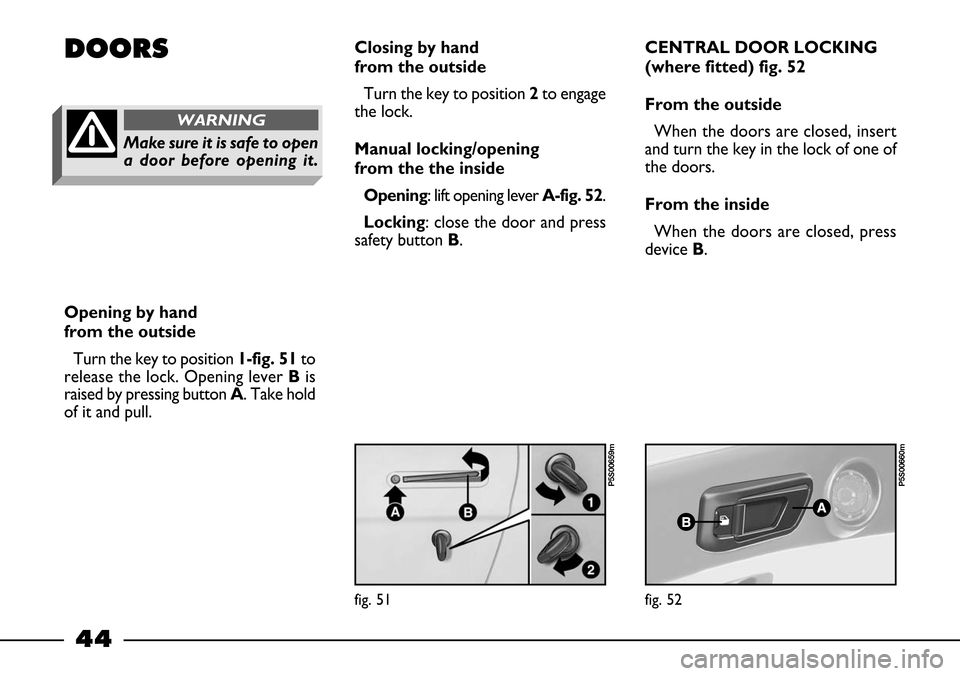
DOORSClosing by hand
from the outside
Turn the key to position 2to engage
the lock.
Manual locking/opening
from the the inside
Opening: lift opening lever A-fig. 52.
Locking: close the door and press
safety button B.CENTRAL DOOR LOCKING
(where fitted) fig. 52
From the outside
When the doors are closed, insert
and turn the key in the lock of one of
the doors.
From the inside
When the doors are closed, press
device B.
Opening by hand
from the outside
Turn the key to position 1-fig. 51to
release the lock. Opening lever Bis
raised by pressing button A. Take hold
of it and pull.
fig. 51
P5S00659m
fig. 52
P5S00660m
Make sure it is safe to open
a door before opening it.
WARNING
Page 46 of 170
45
IMPORTANT If one of the doors
is not shut properly or there is a fail-
ure in the system, the central locking
feature will not work and, after some
attempts, the device stops working for
around two minutes. In these two
minutes the doors can be locked or
unlocked manually without the elec-
trical system coming into play. After
the two minutes the control unit is
ready to receive commands once
more.
If the reason for the malfunction has
been removed, the device will start to
work properly again. If not it will cut
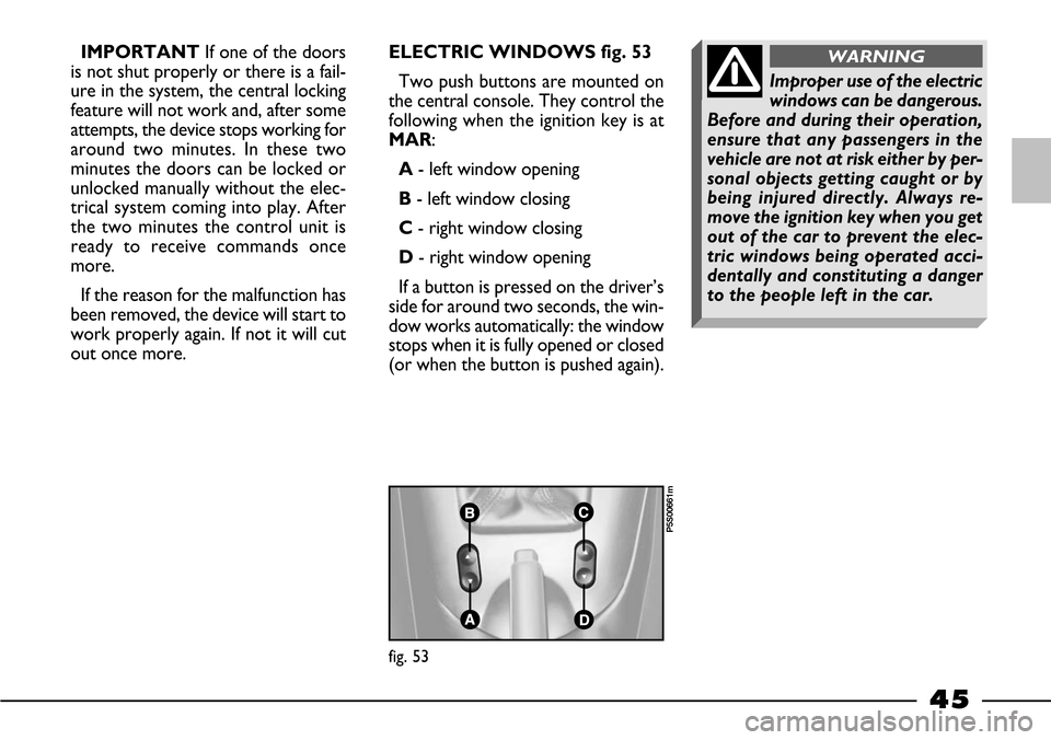
out once more.ELECTRIC WINDOWS fig. 53
Two push buttons are mounted on
the central console. They control the
following when the ignition key is at
MAR:
A- left window opening
B- left window closing
C- right window closing
D- right window opening
If a button is pressed on the driver’s
side for around two seconds, the win-
dow works automatically: the window
stops when it is fully opened or closed
(or when the button is pushed again).
fig. 53
P5S00661m
Improper use of the electric
windows can be dangerous.
Before and during their operation,
ensure that any passengers in the
vehicle are not at risk either by per-
sonal objects getting caught or by
being injured directly. Always re-
move the ignition key when you get
out of the car to prevent the elec-
tric windows being operated acci-
dentally and constituting a danger
to the people left in the car.
WARNING
Page 48 of 170
47
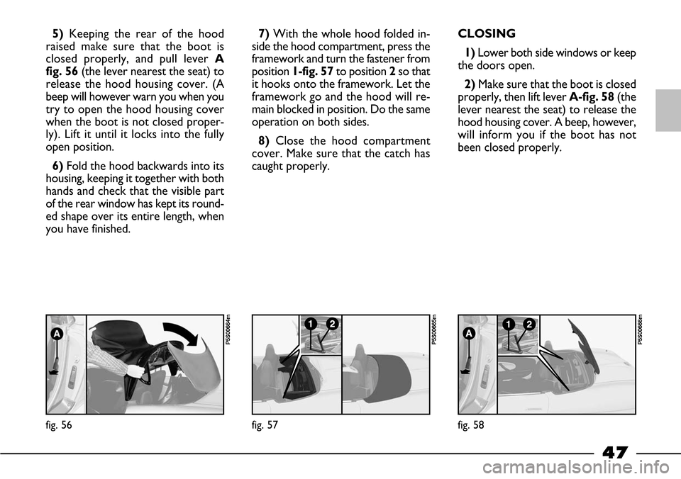
5)Keeping the rear of the hood
raised make sure that the boot is
closed properly, and pull lever A
fig. 56(the lever nearest the seat) to
release the hood housing cover. (A
beep will however warn you when you
try to open the hood housing cover
when the boot is not closed proper-
ly). Lift it until it locks into the fully
open position.
6) Fold the hood backwards into its
housing, keeping it together with both
hands and check that the visible part
of the rear window has kept its round-
ed shape over its entire length, when
you have finished.7) With the whole hood folded in-
side the hood compartment, press the
framework and turn the fastener from
position 1-fig. 57to position 2so that
it hooks onto the framework. Let the
framework go and the hood will re-
main blocked in position. Do the same
operation on both sides.
8)Close the hood compartment
cover. Make sure that the catch has
caught properly.CLOSING
1) Lower both side windows or keep
the doors open.
2)Make sure that the boot is closed
properly, then lift lever A-fig. 58(the
lever nearest the seat) to release the
hood housing cover. A beep, however,
will inform you if the boot has not
been closed properly.
fig. 56
P5S00664m
fig. 57
P5S00665m
fig. 58
P5S00666m
Page 56 of 170
55
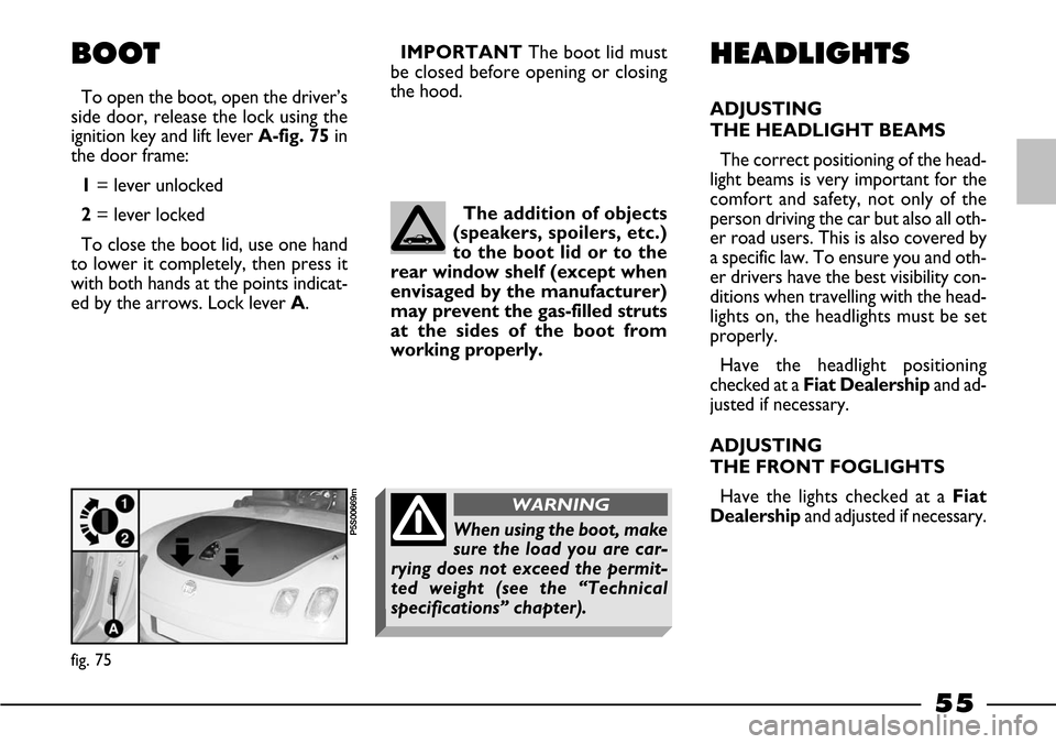
BOOT
To open the boot, open the driver’s
side door, release the lock using the
ignition key and lift lever A-fig. 75in
the door frame:
1= lever unlocked
2= lever locked
To close the boot lid, use one hand
to lower it completely, then press it
with both hands at the points indicat-
ed by the arrows. Lock lever A.IMPORTANTThe boot lid must
be closed before opening or closing
the hood.
HEADLIGHTS
ADJUSTING
THE HEADLIGHT BEAMS
The correct positioning of the head-
light beams is very important for the
comfort and safety, not only of the
person driving the car but also all oth-
er road users. This is also covered by
a specific law. To ensure you and oth-
er drivers have the best visibility con-
ditions when travelling with the head-
lights on, the headlights must be set
properly.
Have the headlight positioning
checked at a Fiat Dealershipand ad-
justed if necessary.
ADJUSTING
THE FRONT FOGLIGHTS
Have the lights checked at a Fiat
Dealershipand adjusted if necessary. The addition of objects
(speakers, spoilers, etc.)
to the boot lid or to the
rear window shelf (except when
envisaged by the manufacturer)
may prevent the gas-filled struts
at the sides of the boot from
working properly.
fig. 75
P5S00669mWhen using the boot, make
sure the load you are car-
rying does not exceed the permit-
ted weight (see the “Technical
specifications” chapter).
WARNING
Page 104 of 170
103
50
15
30
50
40
15
20
15
60
30
20
40
40
30
20
20
15
30
30
30
30
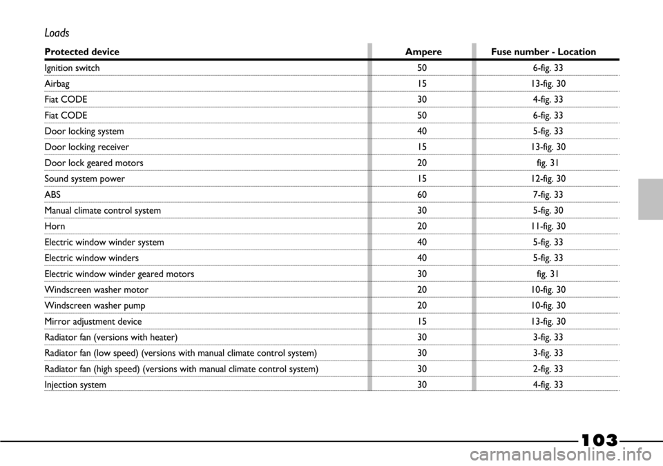
Loads
Protected device Ampere Fuse number - Location
Ignition switch
Airbag
Fiat CODE
Fiat CODE
Door locking system
Door locking receiver
Door lock geared motors
Sound system power
ABS
Manual climate control system
Horn
Electric window winder system
Electric window winders
Electric window winder geared motors
Windscreen washer motor
Windscreen washer pump
Mirror adjustment device
Radiator fan (versions with heater)
Radiator fan (low speed) (versions with manual climate control system)
Radiator fan (high speed) (versions with manual climate control system)
Injection system 6-fig. 33
13-fig. 30
4-fig. 33
6-fig. 33
5-fig. 33
13-fig. 30
fig. 31
12-fig. 30
7-fig. 33
5-fig. 30
11-fig. 30
5-fig. 33
5-fig. 33
fig. 31
10-fig. 30
10-fig. 30
13-fig. 30
3-fig. 33
3-fig. 33
2-fig. 33
4-fig. 33