radio FIAT BARCHETTA 2003 1.G Owners Manual
[x] Cancel search | Manufacturer: FIAT, Model Year: 2003, Model line: BARCHETTA, Model: FIAT BARCHETTA 2003 1.GPages: 170, PDF Size: 3.55 MB
Page 8 of 170
7
DASHBOARD
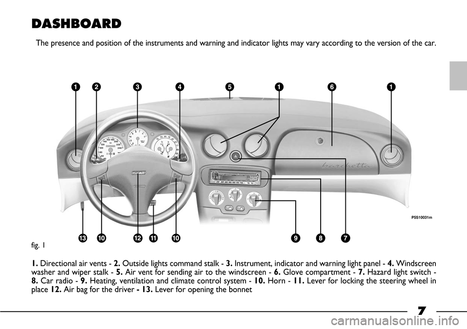
The presence and position of the instruments and warning and indicator lights may vary according to the version of the car.
1.Directional air vents -2.Outside lights command stalk - 3.Instrument, indicator and warning light panel - 4.Windscreen
washer and wiper stalk -5.Air vent for sending air to the windscreen - 6. Glove compartment -7.Hazard light switch -
8. Car radio - 9. Heating, ventilation and climate control system - 10.Horn - 11.Lever for locking the steering wheel in
place 12. Air bag for the driver - 13.Lever for opening the bonnet
fig. 1
P5S10031m
Page 14 of 170
13
DUPLICATING KEYS
If you ask for extra keys, remember
that all the keys, both the new ones
and those you already possess, must
be stored in the memory (up to a
maximum of 7). Go directly to your
nearest Fiat Dealership, taking with
you the key with the burgundy grip, all
the other keys in your possession and
the CODE card.
The codes of any keys that are not
available when the new storage pro-
cedure is carried out will be deleted
from the memory to prevent any lost
or stolen keys being used to start the
car.OPERATION
The electronic alarm fitted to the Fi-
at Barchetta is controlled by the re-
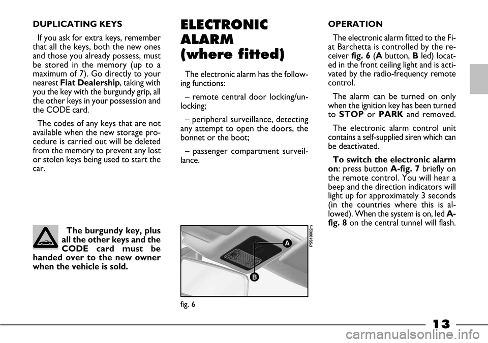
ceiver fig. 6(Abutton, Bled) locat-
ed in the front ceiling light and is acti-
vated by the radio-frequency remote
control.
The alarm can be turned on only
when the ignition key has been turned
toSTOPor PARKand removed.
The electronic alarm control unit
contains a self-supplied siren which can
be deactivated.
To switch the electronic alarm
on: press button A-fig. 7briefly on
the remote control. You will hear a
beep and the direction indicators will
light up for approximately 3 seconds
(in the countries where this is al-
lowed). When the system is on, led A-
fig. 8on the central tunnel will flash.ELECTRONIC
ALARM
(where fitted)
The electronic alarm has the follow-
ing functions:
– remote central door locking/un-
locking;
– peripheral surveillance, detecting
any attempt to open the doors, the
bonnet or the boot;
– passenger compartment surveil-
lance.
The burgundy key, plus
all the other keys and the
CODE card must be
handed over to the new owner
when the vehicle is sold.
fig. 6
P5S10002m
Page 16 of 170
15
THE REMOTE CONTROL
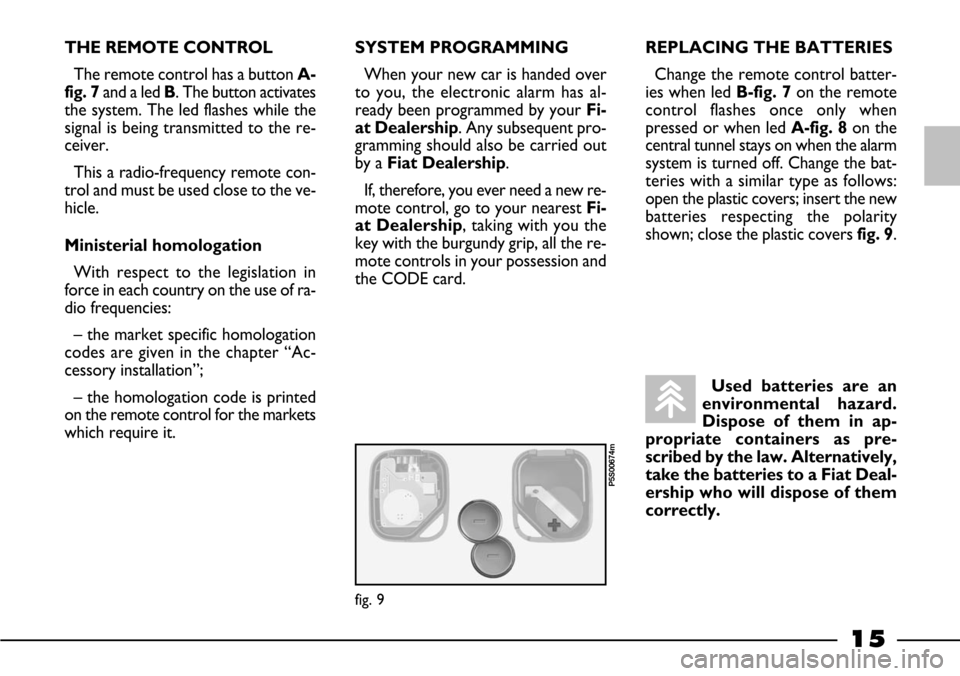
The remote control has a button A-
fig. 7and a led B. The button activates
the system. The led flashes while the
signal is being transmitted to the re-
ceiver.
This a radio-frequency remote con-
trol and must be used close to the ve-
hicle.
Ministerial homologation
With respect to the legislation in
force in each country on the use of ra-
dio frequencies:
– the market specific homologation
codes are given in the chapter “Ac-
cessory installation”;
– the homologation code is printed
on the remote control for the markets
which require it.SYSTEM PROGRAMMING
When your new car is handed over
to you, the electronic alarm has al-
ready been programmed by your Fi-
at Dealership. Any subsequent pro-
gramming should also be carried out
by a Fiat Dealership.
If, therefore, you ever need a new re-
mote control, go to your nearest Fi-
at Dealership, taking with you the
key with the burgundy grip, all the re-
mote controls in your possession and
the CODE card.REPLACING THE BATTERIES
Change the remote control batter-
ies when led B-fig. 7on the remote
control flashes once only when
pressed or when ledA-fig. 8on the
central tunnel stays on when the alarm
system is turned off. Change the bat-
teries with a similar type as follows:
open the plastic covers; insert the new
batteries respecting the polarity
shown; close the plastic covers fig. 9.
Used batteries are an
environmental hazard.
Dispose of them in ap-
propriate containers as pre-
scribed by the law. Alternatively,
take the batteries to a Fiat Deal-
ership who will dispose of them
correctly.
fig. 9
P5S00674m
Page 18 of 170
17
HOW TO KNOW IF
THE ALARM HAS GONE OFF
If the car alarm was triggered while
you were away, led A-fig. 8on the
central tunnel will flash to identify the
reason for it:
Light on: remote control battery
flat.
1 flash: right door.
2 flashes: left door.
5 flashes: passenger compartment
sensors (movement inside the pas-
senger compartment).6 flashes: bonnet.
7 flashes: boot.
8 flashes: ignition tampered with.
9 flashes: alarm power supply cables
cut.
10 flashes: at least three different
causes.
The led will go out when the ignition
key is turned toMARor after 2 min-
utes.IGNITION SWITCH
The key can turn through four dif-
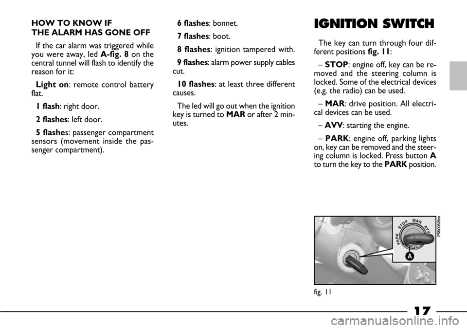
ferent positions fig. 11:
– STOP: engine off, key can be re-
moved and the steering column is
locked. Some of the electrical devices
(e.g. the radio) can be used.
– MAR: drive position. All electri-
cal devices can be used.
– AVV: starting the engine.
– PARK: engine off, parking lights
on, key can be removed and the steer-
ing column is locked. Press button A
to turn the key to the PARKposition.
fig. 11
P5S00626m
Page 83 of 170
82
REPEATED
CHECKS AND
CHECKS BEFORE
LONG TRIPS
Remember to periodically check:
– tyre pressure and condition;
– electrolyte level;
– engine oil level;
– coolant level and condition of the
system;
– brake fluid level;
– windscreen washer liquid;
– power steering fluid.
ACCESSORIES
PURCHASED
BY THE OWNER
RADIO
TRANSMITTERS AND
CELLULAR
TELEPHONES
Cellphones and other radio trans-
mitters (e.g. CB radios) cannot be
used inside the vehicle, unless you
use a separate aerial mounted out-
side the vehicle.
IMPORTANTThe use of cell-
phones, CB radios or similar inside
the passenger compartment (with-
out an outside aerial) produces elec-
tromagnetic RF fields; if these are
amplified by the resonance inside the
passenger compartment, they may
not only result in a potential health
hazard, or poor functioning of the
electronic systems fitted to the vehi-
cle, but also put the safety of your
vehicle in jeopardy.
The transmission and reception
efficiency of this equipment may also
be affected by the shielding effect of
the vehicle's body.
USEFUL
ACCESSORIES
Apart from the legal obligations
currently in force we suggest you
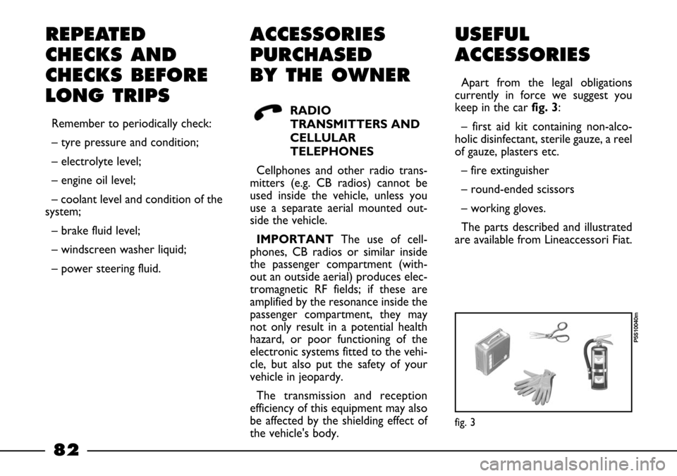
keep in the car fig. 3:
– first aid kit containing non-alco-
holic disinfectant, sterile gauze, a reel
of gauze, plasters etc.
– fire extinguisher
– round-ended scissors
– working gloves.
The parts described and illustrated
are available from Lineaccessori Fiat.
fig. 3
P5S10040m
Page 125 of 170
124
USEFUL ADVICE
FOR LENGTHENING THE
LIFE OF YOUR BATTERY
When you park the car, ensure the
doors, boot and bonnet are closed
properly. The courtesy light must be
off.
Do not keep accessories (e.g. radio,
hazard lights etc.) switched on for a
long time when the engine is not run-
ning.
IMPORTANT A battery which is
kept at a charge of less than 50% for
any length of time will be damaged by
sulphation leading to a reduction in
cranking power and a higher risk of
the battery electrolyte freezing (this
may even occur at –10°C).
If the car is inactive for a long peri-
od of time, refer to “Storing the car”
in the “Driving your car” chapter.If, after purchasing your car you
would like to add electrical accessories
that require a permanent power sup-
ply (alarm systems, hands-free phone,
radio navigator with satellite anti-theft
system, etc.), visit a Fiat Dealership.
The staff of experts, besides suggest-
ing the most suitable accessories in the
Lineaccessori range, will also check
whether the car electrical system can
support the required load or if a larg-
er size battery needs to be installed.
These devices will, in fact, run off the
battery even when the key is not in-
serted (car parked) and can deploy the
battery.
Incorrect fitting of elec-
trical and electronic ac-
cessories can seriously
damage the car.Batteries contain sub-
stances that are very
harmful for the environ-
ment. You are advised to have the
battery changed at a Fiat Dealer-
ship. It is properly equipped for
disposing of used batteries in an
environmentally-friendly way that
complies with the law.
Do not attempt to recharge
a frozen battery. Thaw it
first otherwise it could explode. If
the battery froze, make sure the in-
ternal elements are not broken
(short-circuit risk) and that the cas-
ing is not cracked (risk of spilling
the poisonous and corrosive fluid).
WARNING
Page 126 of 170
125
– Do not connect or disconnect the
terminals of the electronic units while
the ignition key is at MAR.
– Do not check polarity through
sparking.
– Disconnect the electronic units if
you are electrically welding the car
body. Remove the units if tempera-
tures exceed 80°C. (special operations
on the bodywork etc.)
IMPORTANTIf the radio or car
alarm systems are not installed cor-
rectly, they can interfere with the
working of the electronic control
units.ELECTRONIC
CONTROL UNITS
When the car is being used normal-
ly, special measures are not necessary.
The following instructions must be
followed very carefully however, if you
work on the electrical system or in
cases where starting with another bat-
tery is necessary:
– Never disconnect the battery from
the electrical system while the engine
is running.
– When recharging, disconnect the
battery from the wiring system. The
latest battery chargers can, in fact, gen-
erate voltages of up to 20V.
– Never start the engine with a bat-
tery charger. Always use another bat-
tery.
– Be particularly careful when con-
necting the battery to the electrical
system. Ensure the battery posts are
connected up to the right leads (the
polarity is correct) and check that the
connection has been made properly.
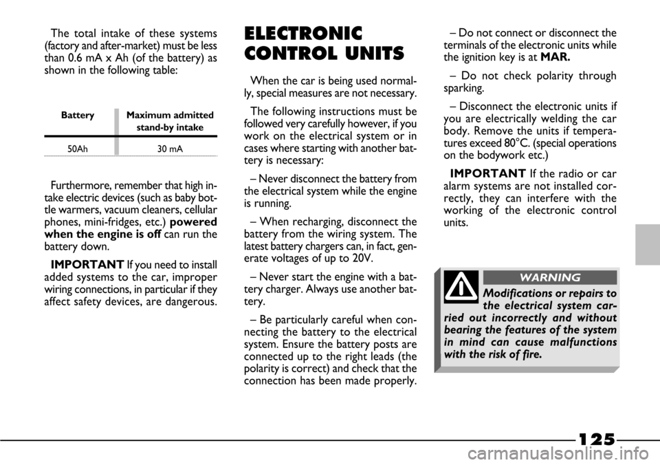
Battery Maximum admitted
stand-by intake
50Ah 30 mA
Furthermore, remember that high in-
take electric devices (such as baby bot-
tle warmers, vacuum cleaners, cellular
phones, mini-fridges, etc.) powered
when the engine is off can run the
battery down.
IMPORTANT If you need to install
added systems to the car, improper
wiring connections, in particular if they
affect safety devices, are dangerous.The total intake of these systems
(factory and after-market) must be less
than 0.6 mA x Ah (of the battery) as
shown in the following table:
Modifications or repairs to
the electrical system car-
ried out incorrectly and without
bearing the features of the system
in mind can cause malfunctions
with the risk of fire.
WARNING
Page 150 of 170
149
ACCESSORY INSTALLATION
Genuine Fiat accessories have been designed with
the Fiat barchetta specifically in mind and have been se-
lected and tested on the car. They are easy to use, re-
liable and practical, qualities that lead to enhanced com-
fort and safety under all driving conditions.
If you wish to give your Fiat barchetta a sportier look,
Fiat has designed light alloy rims, leather panels, spoilers
and sporty bumpers that are fully in keeping with the
car’s line making it more personal and aggressive.
To ensure child safety, the child safety seats offered
by Lineaccessori Fiat meet the requirements of the Eu-
ropean standards currently in force.
You can find accessories from the Fiat line described
in a catalogue available from Fiat Branches, Dealers or
Authorised Workshops. Just ask one of Fiat’s staff to
give you all the details.
The following pages show diagrams and give instruc-
tions for correctly fitting a number of accessories. In-
stallation must always be entrusted to the experts. Fi-
at has specially trained its Dealership staff for work on
the Fiat barchetta.ELECTRONIC CAR ALARM ........................................... 150
TOW HITCH INSTALLATION....................................... 152
HARD TOP .......................................................................... 155
RADIO-FREQUENCY REMOTE CONTROL
MINISTERIAL HOMOLOGATION ............................... 156
Page 151 of 170
150
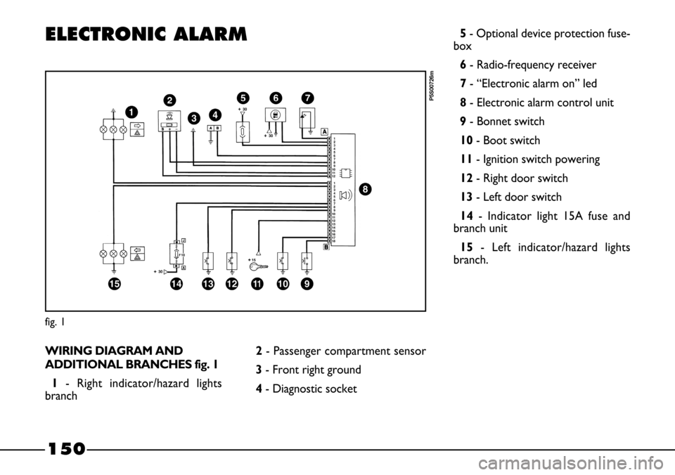
ELECTRONIC ALARM
WIRING DIAGRAM AND
ADDITIONAL BRANCHES fig. 1
1- Right indicator/hazard lights
branch
fig. 1
P5S00726m
2- Passenger compartment sensor
3- Front right ground
4- Diagnostic socket5- Optional device protection fuse-
box
6- Radio-frequency receiver
7- “Electronic alarm on” led
8- Electronic alarm control unit
9- Bonnet switch
10- Boot switch
11- Ignition switch powering
12- Right door switch
13- Left door switch
14- Indicator light 15A fuse and
branch unit
15 - Left indicator/hazard lights
branch.
Page 152 of 170
151
LOCATION
OF COMPONENTS
IN THE VEHICLE fig. 2
A- Radio-frequency receiver in ceil-
ing light
B - “Bonnet open” signal switch con-
trol (adjustable cap)
C- “Bonnet open” signal switch
D- “Right door open”, “left door
open” and “boot open” signal switch
E- Electronic alarm control unit (in
the engine compartment)
F- “Electronic alarm on” warning led
G- Radio-frequency remote control
H- Passenger compartment protec-
tion sensor (located under the central
tunnel).
fig. 2
P5S10042m