wheel bolts FIAT BARCHETTA 2003 1.G Owners Manual
[x] Cancel search | Manufacturer: FIAT, Model Year: 2003, Model line: BARCHETTA, Model: FIAT BARCHETTA 2003 1.GPages: 170, PDF Size: 3.55 MB
Page 87 of 170
86
Observe the instructions on this and
the following pages to use the jack and
space-saver spare wheel correctly.
BUMP STARTING IF A TYRE
IS PUNCTURED
General instructions
Do not bump start by
pushing, towing or coast-
ing downhill. This way of
starting could cause a rush of fu-
el into the catalytic exhaust pipe
and damage it beyond repair.
Signal the presence of the
stopped vehicle according
to the laws in force (e.g. hazard
lights, reflecting triangle, etc.).
Any passengers on board should
leave the vehicle, especially if it is
heavily laden. Passengers should
stay away from oncoming traffic
while the wheel is being changed.
If the wheel is being changed on a
steep or badly surfaced road, place
wedges or other suitable material
under the wheels to stop the vehi-
cle.
WARNING
Remember that if the en-
gine is not running, the
brake booster will not work. You
therefore have to use considerably
more effort on the brake pedal.
WARNING
The space-saver spare
wheel is vehicle-specific.
Never use the wheel on other mod-
els. Never use other model spare
wheels on your vehicle.
If you change the type of wheels
(alloy rims instead of steel rims) you
will have to change the entire set of
fastening bolts with another set of
suitably sized bolts.
Only use the spare-saver wheel for
emergencies.
With the spare wheel do not exceed
80 kph.
An orange sticker is attached to the
spare wheel giving the main in-
structions for its use and limitations.
The sticker must never be re-
moved or covered.
Do not fit the hub cap to the
spare wheel.
WARNING
Page 89 of 170
88
CHANGING A WHEEL
Please note:
– the jack weighs 1.85 kg;
– the jack requires no adjustments;
– the jack cannot be repaired. If it
breaks it must be replaced with a new
jack;
– no other tool, part from the han-
dle shown in this chapter can be fitted
to the jack.
Change the wheel as follows:
1)Stop the vehicle so that it is not
a hazard for other road users or your-
self when changing the wheel. The
ground should be as flat and firm as
possible.2)Stop the engine and engage the
handbrake.
3)Engage first gear or reverse.
4)Lift the boot carpet.
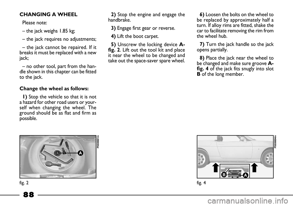
5)Unscrew the locking device A-
fig. 2. Lift out the tool kit and place
it near the wheel to be changed and
take out the space-saver spare wheel.6)Loosen the bolts on the wheel to
be replaced by approximately half a
turn. If alloy rims are fitted, shake the
car to facilitate removing the rim from
the wheel hub.
7)Turn the jack handle so the jack
opens partially.
8)Place the jack near the wheel to
be changed and make sure groove A-
fig. 4of the jack fits snugly into slot
Bof the long member.
fig. 2
P5S00681m
fig. 4
P5S00694m
Page 90 of 170
89
Depending on whether the normal
wheels are fitted with steel or light al-
loy rims, the spare wheel (always
made of steel) differs in order to be
compatible with the wheel bolts which
are specific for each of the two types
of rim.
If the type of wheel to be used is to
be changed (alloy rims in place of steel
rims and vice-versa) the bolts must al-
so be changed and a specific spare
wheel adopted.
Keep the bolts and the spare wheel
as they are essential if the original
wheels are to be refitted at some time
in the future. 9) Warn anyone nearby that the ve-
hicle is about to be lifted. They must
stay clear and not touch the vehicle
until it is back on the ground.
10) Turn the jack handle and raise
the car until the wheel is a few cen-
timetres above the ground.
The jack handle must turn freely,
without touching the ground to avoid
scraping your hands. Do not touch the
moving parts of the jack as they can
cause injuries. If you dirty your hands
with grease, clean them carefully.
11) Fully unscrew the 4 bolts, re-
move the wheel and, where provided
recover the wheel hub cap.
12)Make sure the surfaces of the
space-saver spare wheel that come in-
to contact with the hub are clean and
free from any impurities which could
result in the wheel bolts working
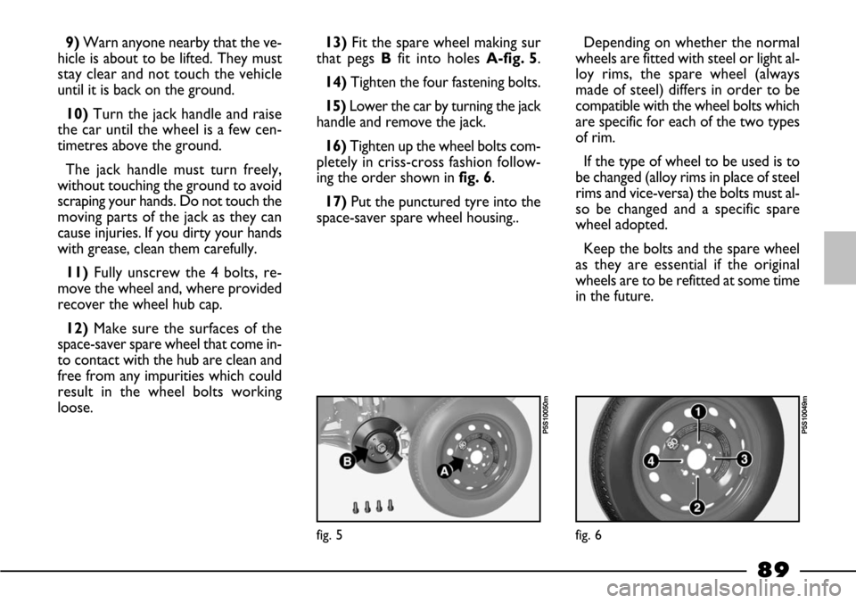
loose.13)Fit the spare wheel making sur
that pegs Bfit into holes A-fig. 5.
14) Tighten the four fastening bolts.
15) Lower the car by turning the jack
handle and remove the jack.
16)Tighten up the wheel bolts com-
pletely in criss-cross fashion follow-
ing the order shown in fig. 6.
17) Put the punctured tyre into the
space-saver spare wheel housing..
fig. 5
P5S10050m
fig. 6
P5S10049m
Page 91 of 170
90
3)Screw up the bolts with the span-
ner provided.
4) Lower the vehicle and remove the
jack.
5)Tighten up the bolts in the same
order as shown above.When you have finished
1)Put the space-saver spare wheel
back in the boot.
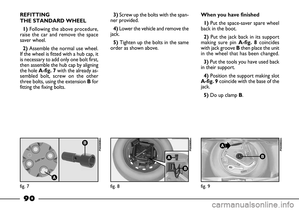
2) Put the jack back in its support
making sure pin A-fig. 8coincides
with jack groove Bthen place the unit
in the wheel that has been changed.
3) Put the tools you have used back
in their support.
4)Position the support making slot
A-fig. 9coincide with the base of the
jack.
5)Do up clamp B. REFITTING
THE STANDARD WHEEL
1) Following the above procedure,
raise the car and remove the space
saver wheel.
2)Assemble the normal use wheel.
If the wheel is fitted with a hub cap, it
is necessary to add only one bolt first,
then assemble the hub cap by aligning
the hole A-fig. 7with the already as-
sembled bolt, screw on the other
three bolts, using the extension Bfor
fitting the fixing bolts.
fig. 7
P5S00696m
fig. 8
P5S00695m
fig. 9
P5S00682m
Page 142 of 170
141
WHEELS
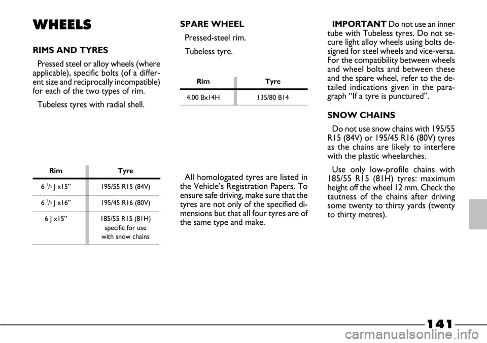
RIMS AND TYRES
Pressed steel or alloy wheels (where
applicable), specific bolts (of a differ-
ent size and reciprocally incompatible)
for each of the two types of rim.
Tubeless tyres with radial shell.IMPORTANT Do not use an inner
tube with Tubeless tyres. Do not se-
cure light alloy wheels using bolts de-
signed for steel wheels and vice-versa.
For the compatibility between wheels
and wheel bolts and between these
and the spare wheel, refer to the de-
tailed indications given in the para-
graph “If a tyre is punctured”.
SNOW CHAINS
Do not use snow chains with 195/55
R15 (84V) or 195/45 R16 (80V) tyres
as the chains are likely to interfere
with the plastic wheelarches.
Use only low-profile chains with
185/55 R15 (81H) tyres: maximum
height off the wheel 12 mm. Check the
tautness of the chains after driving
some twenty to thirty yards (twenty
to thirty metres).
Rim Tyre
6 1/2J x15” 195/55 R15 (84V)
6 1/2J x16” 195/45 R16 (80V)
6 J x15” 185/55 R15 (81H)
specific for use
with snow chains
SPARE WHEEL
Pressed-steel rim.
Tubeless tyre.
All homologated tyres are listed in
the Vehicle’s Registration Papers. To
ensure safe driving, make sure that the
tyres are not only of the specified di-
mensions but that all four tyres are of
the same type and make.
Rim Tyre
4.00 Bx14H 135/80 B14
Page 154 of 170
153
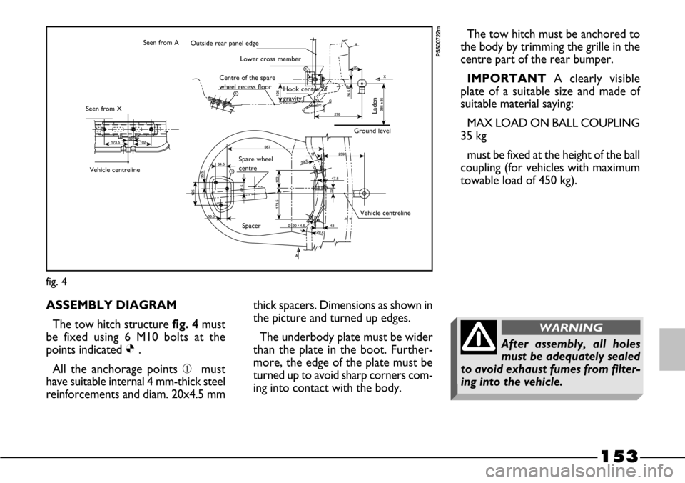
ASSEMBLY DIAGRAM
The tow hitch structure fig. 4must
be fixed using 6 M10 bolts at the
points indicated Ø.
All the anchorage points ➀must
have suitable internal 4 mm-thick steel
reinforcements and diam. 20x4.5 mmthick spacers. Dimensions as shown in
the picture and turned up edges.
The underbody plate must be wider
than the plate in the boot. Further-
more, the edge of the plate must be
turned up to avoid sharp corners com-
ing into contact with the body.
fig. 4
P5S00722m
The tow hitch must be anchored to
the body by trimming the grille in the
centre part of the rear bumper.
IMPORTANTA clearly visible
plate of a suitable size and made of
suitable material saying:
MAX LOAD ON BALL COUPLING
35 kg
must be fixed at the height of the ball
coupling (for vehicles with maximum
towable load of 450 kg).Outside rear panel edge
Lower cross member
Laden
Ground level Hook centre of
gravity Centre of the spare
wheel recess floor
Seen from X
Vehicle centreline
Vehicle centreline
Spacer Spare wheel
centre Seen from A
After assembly, all holes
must be adequately sealed
to avoid exhaust fumes from filter-
ing into the vehicle.
WARNING