start FIAT CROMA 2006 2.G User Guide
[x] Cancel search | Manufacturer: FIAT, Model Year: 2006, Model line: CROMA, Model: FIAT CROMA 2006 2.GPages: 240, PDF Size: 7.41 MB
Page 30 of 240
30
SAFETY
DEVICES
CORRECT USE
OF THE CAR
WARNING
LIGHTS AND
MESSAGES
IN AN
EMERGENCY
CAR
MAINTENANCE
TECHNICAL
SPECIFICATIONS
INDEX
DASHBOARD
AND CONTROLS
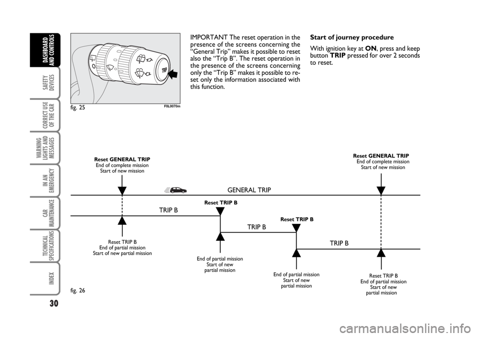
IMPORTANT The reset operation in the
presence of the screens concerning the
“General Trip” makes it possible to reset
also the “Trip B”. The reset operation in
the presence of the screens concerning
only the “Trip B” makes it possible to re-
set only the information associated with
this function.Start of journey procedure
With ignition key at ON, press and keep
button TRIPpressed for over 2 seconds
to reset.
F0L0070mfig. 25
Reset TRIP B
End of partial mission
Start of new partial mission
End of partial mission
Start of new
partial mission
Reset TRIP B
End of partial mission
Start of new
partial mission Reset GENERAL TRIP
End of complete mission
Start of new missionReset GENERAL TRIP
End of complete mission
Start of new mission
End of partial mission
Start of new
partial mission Reset TRIP B
Reset TRIP B
TRIP B
TRIP B
TRIP B GENERAL TRIP˙
˙
˙
˙˙
˙
˙ ˙
fig. 26
001-030 Croma TRW GB 20-11-2006 14:58 Pagina 30
Page 33 of 240
ELECTRICALLY ADJUSTABLE
FRONT SEATS
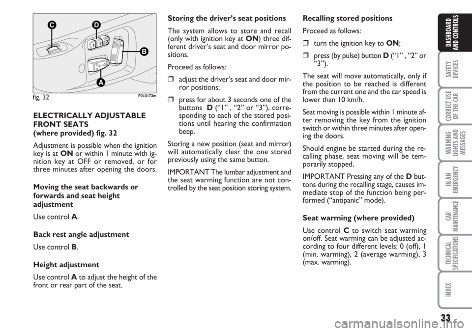
(where provided) fig. 32
Adjustment is possible when the ignition
key is at ONor within 1 minute with ig-
nition key at OFF or removed, or for
three minutes after opening the doors.
Moving the seat backwards or
forwards and seat height
adjustment
Use control A.
Back rest angle adjustment
Use control B.
Height adjustment
Use control Ato adjust the height of the
front or rear part of the seat.
fig. 32F0L0173m
33
SAFETY
DEVICES
CORRECT USE
OF THE CAR
WARNING
LIGHTS AND
MESSAGES
IN AN
EMERGENCY
CAR
MAINTENANCE
TECHNICAL
SPECIFICATIONS
INDEX
DASHBOARD
AND CONTROLS
Storing the driver’s seat positions
The system allows to store and recall
(only with ignition key at ON) three dif-
ferent driver’s seat and door mirror po-
sitions.
Proceed as follows:
❒adjust the driver’s seat and door mir-
ror positions;
❒press for about 3 seconds one of the
buttons D(“1” , “2” or “3”), corre-
sponding to each of the stored posi-
tions until hearing the confirmation
beep.
Storing a new position (seat and mirror)
will automatically clear the one stored
previously using the same button.
IMPORTANT The lumbar adjustment and
the seat warming function are not con-
trolled by the seat position storing system.Recalling stored positions
Proceed as follows:
❒turn the ignition key to ON;
❒press (by pulse) button D(“1” , “2” or
“3”).
The seat will move automatically, only if
the position to be reached is different
from the current one and the car speed is
lower than 10 km/h.
Seat moving is possible within 1 minute af-
ter removing the key from the ignition
switch or within three minutes after open-
ing the doors.
Should engine be started during the re-
calling phase, seat moving will be tem-
porarily stopped.
IMPORTANT Pressing any of the Dbut-
tons during the recalling stage, causes im-
mediate stop of the function being per-
formed (“antipanic” mode).
Seat warming (where provided)
Use control Cto switch seat warming
on/off. Seat warming can be adjusted ac-
cording to four different levels: 0 (off), 1
(min. warming), 2 (average warming), 3
(max. warming).
Page 36 of 240
36
SAFETY
DEVICES
CORRECT USE
OF THE CAR
WARNING
LIGHTS AND
MESSAGES
IN AN
EMERGENCY
CAR
MAINTENANCE
TECHNICAL
SPECIFICATIONS
INDEX
DASHBOARD
AND CONTROLS
fig. 37F0L0012m
REARVIEW MIRRORS
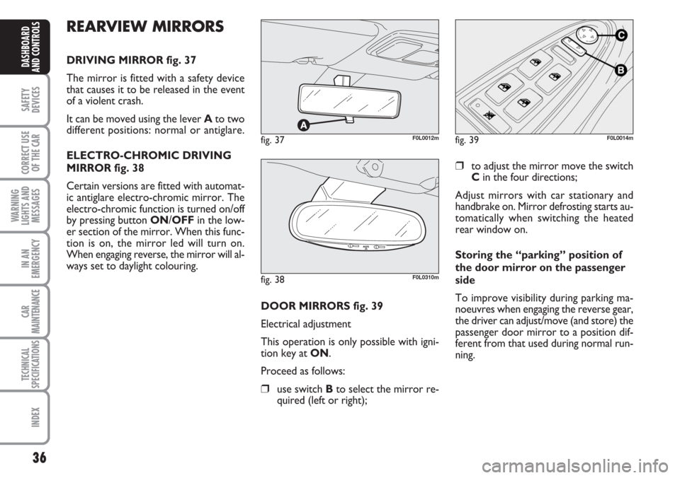
DRIVING MIRROR fig. 37
The mirror is fitted with a safety device
that causes it to be released in the event
of a violent crash.
It can be moved using the lever Ato two
different positions: normal or antiglare.
ELECTRO-CHROMIC DRIVING
MIRROR fig. 38
Certain versions are fitted with automat-
ic antiglare electro-chromic mirror. The
electro-chromic function is turned on/off
by pressing button ON/OFFin the low-
er section of the mirror. When this func-
tion is on, the mirror led will turn on.
When engaging reverse, the mirror will al-
ways set to daylight colouring.
DOOR MIRRORS fig. 39
Electrical adjustment
This operation is only possible with igni-
tion key at ON.
Proceed as follows:
❒use switch Bto select the mirror re-
quired (left or right);
❒to adjust the mirror move the switch
Cin the four directions;
Adjust mirrors with car stationary and
handbrake on. Mirror defrosting starts au-
tomatically when switching the heated
rear window on.
Storing the “parking” position of
the door mirror on the passenger
side
To improve visibility during parking ma-
noeuvres when engaging the reverse gear,
the driver can adjust/move (and store) the
passenger door mirror to a position dif-
ferent from that used during normal run-
ning.
fig. 38F0L0310m
fig. 39F0L0014m
Page 43 of 240
43
SAFETY
DEVICES
CORRECT USE
OF THE CAR
WARNING
LIGHTS AND
MESSAGES
IN AN
EMERGENCY
CAR
MAINTENANCE
TECHNICAL
SPECIFICATIONS
INDEX
DASHBOARD
AND CONTROLS
Window demisting
In the event of considerable outside mois-
ture and/or rain and/or considerable dif-
ferences in temperature inside and out-
side the passenger compartment, perform
the following preventive demisting proce-
dure:
❒turn air recirculation off by pressing
button G(button led off);
❒turn knob Cto red sector;
❒turn knob Eto 2;
❒turn knob Ato y, or to ™the win-
dows do not demist.
IMPORTANT Climate control system is
very useful to speed up window demist-
ing: therefore, just perform demisting as
previously described and turn the climate
control system on by pressing button B.HEATED REAR WINDOW AND
DOOR MIRROR DEMISTING/
DEFROSTING
Press button Fto start this function.
This function is timed and switches off au-
tomatically after 30 minutes. To cut out
this function press again button
O.
IMPORTANT Do not apply stickers on
the inside of the rear window over the
heating filaments to avoid damage that
might cause it to stop working properly.
FAN SPEED ADJUSTMENT
To ventilate the passenger’s compartment
properly, proceed as follows:
❒open completely central vents and side
outlets;
❒turn knob Cto the blue sector;
❒turn knob Eto the required speed;
❒turn air recirculation off by pressing
button G(button led off);
❒turn knob Ato O.RECIRCULATION
Turn this function on by pressing button
G(button led on).
This function is particularly useful when
the outside air is heavily polluted (in a traf-
fic jam, tunnel, etc.). However, it is bet-
ter not to use it for long periods, espe-
cially if there are several people in the car
to prevent window misting.
IMPORTANT The inside air recirculation
system makes it possible to reach the re-
quired “heating” or “cooling” conditions
faster. Do not use the air recirculation
function on rainy/cold days as it would
considerably increase the possibility of the
windows misting inside.
Page 46 of 240
46
SAFETY
DEVICES
CORRECT USE
OF THE CAR
WARNING
LIGHTS AND
MESSAGES
IN AN
EMERGENCY
CAR
MAINTENANCE
TECHNICAL
SPECIFICATIONS
INDEX
DASHBOARD
AND CONTROLS
SWITCHING THE CLIMATE
CONTROL SYSTEM ON
The system can be started in different
ways, but it is advisable to press one of the
AUTObuttons and then to turn the
knobs to set the temperatures required
on the display.
Since the system controls two zone of the
passenger’s compartment, the driver and
the front passenger can select different
temperatures.This way the system will start working
completely automatically to reach the
comfort temperatures as quickly as pos-
sible. The system will set air temperature,
quantity and distribution and it will con-
trol the air recirculation function and the
activation of conditioner compressor.
F0L0020mfig. 47
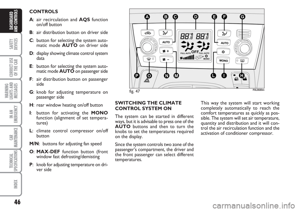
CONTROLS
A: air recirculation and AQS function
on/off button
B: air distribution button on driver side
C: button for selecting the system auto-
matic mode AUTO on driver side
D: display showing climate control system
data
E: button for selecting the system auto-
matic mode AUTO on passenger side
F: air distribution button on passenger
side
G: knob for adjusting temperature on
passenger side
H: rear window heating on/off button
I: button for activating the MONO
function (alignment of set tempera-
tures)
L: climate control compressor on/off
button
M/N: buttons for adjusting fan speed
O:MAX-DEF function button (front
window fast defrosting/demisting
P: knob for adjusting temperature on dri-
ver side
Page 50 of 240
50
SAFETY
DEVICES
CORRECT USE
OF THE CAR
WARNING
LIGHTS AND
MESSAGES
IN AN
EMERGENCY
CAR
MAINTENANCE
TECHNICAL
SPECIFICATIONS
INDEX
DASHBOARD
AND CONTROLS
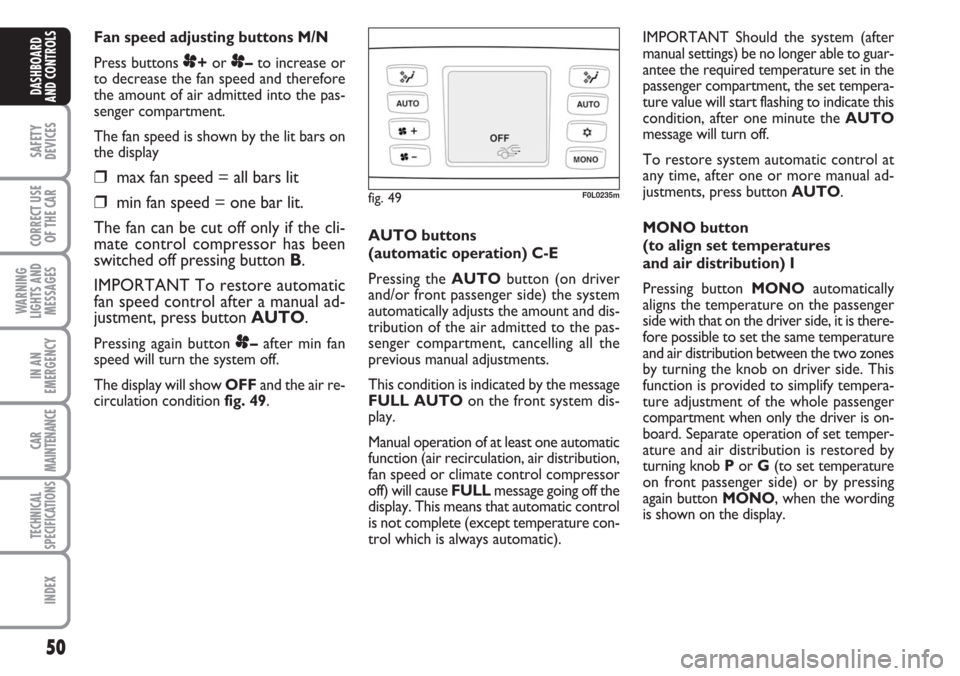
Fan speed adjusting buttons M/N
Press buttons
p+or p–to increase or
to decrease the fan speed and therefore
the amount of air admitted into the pas-
senger compartment.
The fan speed is shown by the lit bars on
the display
❒max fan speed = all bars lit
❒min fan speed = one bar lit.
The fan can be cut off only if the cli-
mate control compressor has been
switched off pressing button B.
IMPORTANT To restore automatic
fan speed control after a manual ad-
justment, press button AUTO.
Pressing again button p–after min fan
speed will turn the system off.
The display will show OFFand the air re-
circulation condition fig. 49. AUTO buttons
(automatic operation) C-E
Pressing the AUTObutton (on driver
and/or front passenger side) the system
automatically adjusts the amount and dis-
tribution of the air admitted to the pas-
senger compartment, cancelling all the
previous manual adjustments.
This condition is indicated by the message
FULL AUTOon the front system dis-
play.
Manual operation of at least one automatic
function (air recirculation, air distribution,
fan speed or climate control compressor
off) will cause FULL message going off the
display. This means that automatic control
is not complete (except temperature con-
trol which is always automatic).IMPORTANT Should the system (after
manual settings) be no longer able to guar-
antee the required temperature set in the
passenger compartment, the set tempera-
ture value will start flashing to indicate this
condition, after one minute the AUTO
message will turn off.
To restore system automatic control at
any time, after one or more manual ad-
justments, press button AUTO.
MONO button
(to align set temperatures
and air distribution) I
Pressing button MONOautomatically
aligns the temperature on the passenger
side with that on the driver side, it is there-
fore possible to set the same temperature
and air distribution between the two zones
by turning the knob on driver side. This
function is provided to simplify tempera-
ture adjustment of the whole passenger
compartment when only the driver is on-
board. Separate operation of set temper-
ature and air distribution is restored by
turning knob Por G(to set temperature
on front passenger side) or by pressing
again button MONO, when the wording
is shown on the display.
fig. 49F0L0235m
Page 52 of 240
52
SAFETY
DEVICES
CORRECT USE
OF THE CAR
WARNING
LIGHTS AND
MESSAGES
IN AN
EMERGENCY
CAR
MAINTENANCE
TECHNICAL
SPECIFICATIONS
INDEX
DASHBOARD
AND CONTROLS
Climate control compressor on/off
button L
Pressing button
√when the symbol is dis-
played will deactivate the climate control
system compressor. Pressing the button
when the symbol is not displayed will re-
sume automatic control of compressor ac-
tivation; this condition is indicated by the
relevant symbol on the display.
When turning the compressor off, the sys-
tem will deactivate air recirculation to pre-
vent window misting up. Although the sys-
tem is able to keep the required temper-
ature, the wording FULLwill disappear
from the display. If the system is no longer
able to keep the required temperature,
temperature value will flash and the word-
ing AUTOwill disappear from the display.
IMPORTANT With the climate control
compressor off, it is not possible to admit
air to the passenger compartment with a
temperature below the outside tempera-
ture; moreover, under certain environ-
mental conditions, windows could mist up
fastly since air is not dehumidified.The switching off of the climate control
compressor remains in storage even when
the engine has been stopped.
To restore automatic control for switch-
ing on the climate control compressor,
press again button
√or press button AU-
TO.
With climate control compressor off if
outside temperature is higher than the set
one the system will not be able to keep
the required condition, the temperature
value will then start to flash on the display
for a few seconds and wording AUTO
will then go off.
With climate control compressor off, the
fan speed can be set to zero manually.
With compressor on and engine running,
the fan speed cannot be lower that one
bar on the display.
Compressor will be disabled automatical-
ly with outside temperature below – 1°C.
Under this condition symbol
√on the dis-
play will flash for 10 seconds and then go
off.
It will be re-enabled automatically with
outside temperature higher than + 1°C. Fast window demisting/defrosting
button O
Press this button: the climate control sys-
tem will automatically switch on all the
functions required for fast windscreen and
front side window demisting/defrosting,
that is:
❒switches on climate control compres-
sor when climatic conditions are suit-
able;
❒air recirculation off;
❒maximum air temperature (HI) on
both areas;
❒activates proper fan speed according
to engine coolant temperature to lim-
it the flow into the passenger com-
partment of air not warm enough to
demist the windows;
❒directs air flow to windscreen and
front side windows vents;
❒turns heated rear window on.
IMPORTANT Fast demisting/defrosting
function stays on for about 3 minutes,
since engine coolant temperature exceeds
50°C.
Page 53 of 240
53
SAFETY
DEVICES
CORRECT USE
OF THE CAR
WARNING
LIGHTS AND
MESSAGES
IN AN
EMERGENCY
CAR
MAINTENANCE
TECHNICAL
SPECIFICATIONS
INDEX
DASHBOARD
AND CONTROLS
When the max. demisting/defrosting func-
tion is on, the button led and the heated
rear window button led are on. FULL
AUTOwording on the display is off.
When the max. demisting/defrosting func-
tion is on, the only manual operations pos-
sible are manual adjustment of the fan
speed and switching heated rear window
off.
With max. demisting/defrosting function
on, the fan works according to the previ-
ously set air distribution in order to guar-
antee top climatic comfort under what-
ever condition.
Pressing the max. demisting/defrosting
button or the air distribution buttons or
operating the temperature knobs, the sys-
tem switches off the max. demisting/de-
frosting function and restores the operat-
ing conditions of the system prior to func-
tion activation.Heated rear window and door
mirror demisting/defrosting
button H
Press this button to activate heated rear
window demisting/defrosting. When this
function is on, the button led is on.
This function is timed and switches off au-
tomatically after about 20 minutes or by
pressing again the button or by turning the
engine off. It will not be switched on au-
tomatically when restarting the engine.
IMPORTANT Do not apply stickers on
the inside of the rear window over the
heating filaments to avoid damage that
might cause it to stop working properly.ADDITIONAL HEATER
(Multijet versions)
This device enables quick warming up of
the passenger’s compartment in cold en-
vironmental conditions.
The additional heater will switch on au-
tomatically after turning the ignition key
to ON.
IMPORTANT The additional heater
works only with outside temperature be-
low 12°C, engine coolant temperature be-
low 50°C and car battery voltage over
10.25 V.
IMPORTANT Do not park the car over
flammable material such as paper, dry
grass or leaves: fire danger.
Page 58 of 240
58
SAFETY
DEVICES
CORRECT USE
OF THE CAR
WARNING
LIGHTS AND
MESSAGES
IN AN
EMERGENCY
CAR
MAINTENANCE
TECHNICAL
SPECIFICATIONS
INDEX
DASHBOARD
AND CONTROLS
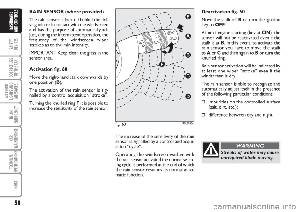
RAIN SENSOR (where provided)
The rain sensor is located behind the dri-
ving mirror in contact with the windscreen
and has the purpose of automatically ad-
just, during the intermittent operation, the
frequency of the windscreen wiper
strokes as to the rain intensity.
IMPORTANT Keep clean the glass in the
sensor area.
Activation fig. 60
Move the right-hand stalk downwards by
one position (B).
The activation of the rain sensor is sig-
nalled by a control acquisition “stroke”.
Turning the knurled ring Fit is possible to
increase the sensitivity of the rain sensor.
The increase of the sensitivity of the rain
sensor is signalled by a control and acqui-
sition “cycle”.
Operating the windscreen washer with
the rain sensor activated the normal wash-
ing cycle is performed at the end of which
the rain sensor resumes its normal auto-
matic function.Deactivation fig. 60
Move the stalk off Bor turn the ignition
key to OFF.
At next engine starting (key at ON), the
sensor will not be reactivated even if the
stalk is at B. In this event, to activate the
rain sensor you have to move the stalk
to Aor Cand then again to Bor turn the
knurled ring.
Rain sensor activation will be indicated by
at least one wiper “stroke” even if the
windscreen is dry.
The rain sensor is able to recognize and
automatically adjust itself in the presence
of the following particular conditions:
❒impurities on the controlled surface
(salt, dirt, etc.);
❒difference between day and night.
fig. 60F0L0030m
Streaks of water may cause
unrequired blade moving.
WARNING
Page 64 of 240
64
SAFETY
DEVICES
CORRECT USE
OF THE CAR
WARNING
LIGHTS AND
MESSAGES
IN AN
EMERGENCY
CAR
MAINTENANCE
TECHNICAL
SPECIFICATIONS
INDEX
DASHBOARD
AND CONTROLS
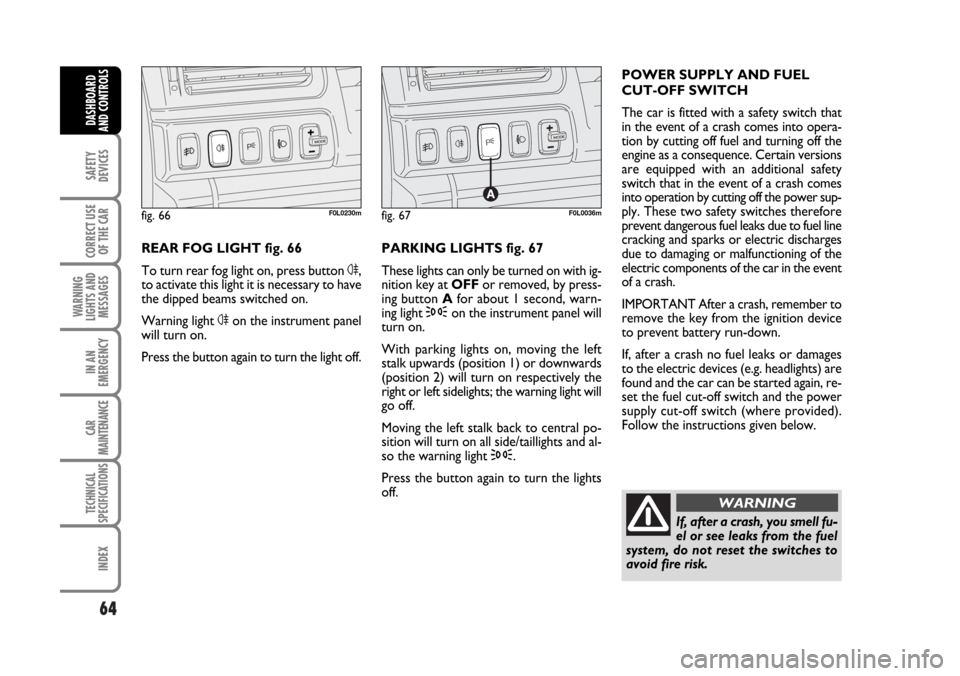
REAR FOG LIGHT fig. 66
To turn rear fog light on, press button 4,
to activate this light it is necessary to have
the dipped beams switched on.
Warning light 4on the instrument panel
will turn on.
Press the button again to turn the light off.PARKING LIGHTS fig. 67
These lights can only be turned on with ig-
nition key at OFFor removed, by press-
ing button Afor about 1 second, warn-
ing light 3on the instrument panel will
turn on.
With parking lights on, moving the left
stalk upwards (position 1) or downwards
(position 2) will turn on respectively the
right or left sidelights; the warning light will
go off.
Moving the left stalk back to central po-
sition will turn on all side/taillights and al-
so the warning light 3.
Press the button again to turn the lights
off. POWER SUPPLY AND FUEL
CUT-OFF SWITCH
The car is fitted with a safety switch that
in the event of a crash comes into opera-
tion by cutting off fuel and turning off the
engine as a consequence. Certain versions
are equipped with an additional safety
switch that in the event of a crash comes
into operation by cutting off the power sup-
ply. These two safety switches therefore
prevent dangerous fuel leaks due to fuel line
cracking and sparks or electric discharges
due to damaging or malfunctioning of the
electric components of the car in the event
of a crash.
IMPORTANT After a crash, remember to
remove the key from the ignition device
to prevent battery run-down.
If, after a crash no fuel leaks or damages
to the electric devices (e.g. headlights) are
found and the car can be started again, re-
set the fuel cut-off switch and the power
supply cut-off switch (where provided).
Follow the instructions given below.
fig. 66F0L0230mfig. 67F0L0036m
If, after a crash, you smell fu-
el or see leaks from the fuel
system, do not reset the switches to
avoid fire risk.
WARNING
062-098 Croma TRW GB 20-11-2006 15:01 Pagina 64