change time FIAT CROMA 2006 2.G Owners Manual
[x] Cancel search | Manufacturer: FIAT, Model Year: 2006, Model line: CROMA, Model: FIAT CROMA 2006 2.GPages: 240, PDF Size: 7.41 MB
Page 7 of 240
THE FIAT CODE SYSTEM
To further protect your car from theft, it
has been fitted with an engine immobilising
system. This system is automatically acti-
vated when the ignition key is removed.
An electronic device, in fact, is fitted in each
ignition key grip. The device transmits a ra-
dio-frequency signal when the engine is
started through a special aerial built into the
ignition switch. The modulate signal, which
changes each time the engine is started, is
the “password”, by means of which the
control unit recognises the key and enables
to start the engine.
OPERATION
Each time the key is fitted into the ignition
switch, the Fiat CODE system control unit
sends a recognition code to the engine con-
trol unit to deactivate the inhibitor.
The code is sent only if the Fiat CODE sys-
tem control unit has recognised the code
transmitted from the key.
Each time the ignition key is removed, the
Fiat CODE system deactivates the func-
tions of the engine electronic control unit.
If the code has not been recognised cor-
rectly, the warning light
Yturns on ac-
companied by the related message on the
display (see chapter “Warning lights and
messages”).
SYMBOLS
Special coloured labels have been attached
near or actually on some of the compo-
nents of your car. These labels bear sym-
bols that remind you of the precautions
to be taken as regards that particular com-
ponent.
7
SAFETY
DEVICES
CORRECT USE
OF THE CAR
WARNING
LIGHTS AND
MESSAGES
IN AN
EMERGENCY
CAR
MAINTENANCE
TECHNICAL
SPECIFICATIONS
INDEX
DASHBOARD
AND CONTROLS
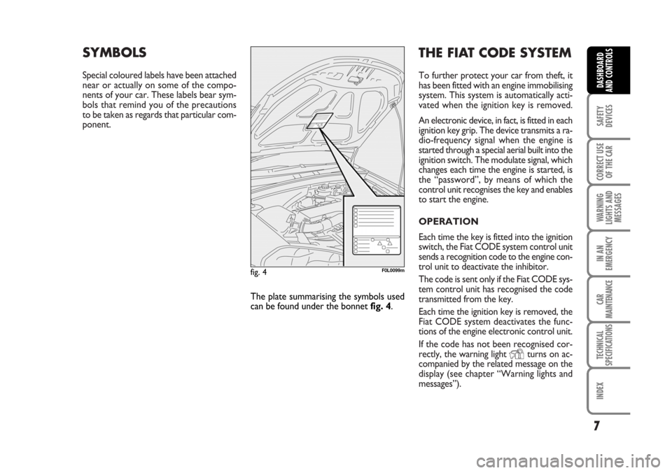
The plate summarising the symbols used
can be found under the bonnet fig. 4.
fig. 4F0L0099m
001-030 Croma TRW GB 20-11-2006 14:58 Pagina 7
Page 21 of 240

21
SAFETY
DEVICES
CORRECT USE
OF THE CAR
WARNING
LIGHTS AND
MESSAGES
IN AN
EMERGENCY
CAR
MAINTENANCE
TECHNICAL
SPECIFICATIONS
INDEX
DASHBOARD
AND CONTROLS
SETUP MENU fig. 24
The menu comprises a series of functions
arranged in a “circular fashion” which can
be selected through buttons +and –to
access the different select operations and
settings (setup) given in the following para-
graphs.
The setup menu can be activated by press-
ing briefly button MODE, only with the
car turned on (with car off, only the re-
duced menu can be displayed).
Single presses on buttons +or –will scroll
the setup menu options.
Handling modes differ with each other ac-
cording to the characteristic of the option
selected.
NOTE If the car is equipped with the Ra-
dionavigation System, the only functions
that can be adjusted/set through the in-
strument panel display are the following:
“Speed limit”, “Automatic headlight day-
light sensor” (where provided) and “S.B.R.
(Seat Belt Reminder) buzzer reactivation”
(where provided). The other functions are
displayed by and can be adjusted/set
through the Radionavigation System dis-
play.Selecting a menu option
– press briefly button MODEto select
the menu option to set;
– press buttons +or –(by single press-
es) to select the new setting;
– press briefly button MODEto store the
new setting and to go back to the previ-
ously selected menu option.
Selecting “Date” and “Set Clock”:
– briefly press button MODEto select
the first value to change (e.g. hours /min-
utes or year / month / day);
– press buttons +or –(by single press-
es) to select the new setting;
– briefly press button MODEto store the
new setting and to go to the next setup
menu option, if this is the last one you will
go back to the previously selected option of
the main menu.Press button MODE for long:
– to quit the setup menu and to save on-
ly the settings stored yet by the user (and
confirmed by pressing briefly button
MODE).
The setup menu displaying is timed; when
quitting the menu due to timing expiry,
only settings stored yet by the user (and
confirmed by pressing briefly button
MODE) will be saved.
001-030 Croma TRW GB 20-11-2006 14:58 Pagina 21
Page 47 of 240
47
SAFETY
DEVICES
CORRECT USE
OF THE CAR
WARNING
LIGHTS AND
MESSAGES
IN AN
EMERGENCY
CAR
MAINTENANCE
TECHNICAL
SPECIFICATIONS
INDEX
DASHBOARD
AND CONTROLS
During fully automatic operation, the on-
ly manual settings required are the fol-
lowing:
❒MONO, to align the air temperature
and distribution set on the passenger’s
side (front or rear) with that on the
driver’s side;
❒…, air recirculation, to keep it al-
ways on or off;
❒-, to speed up demisting/defrosting
of windscreen, front side windows,
rear window and door mirrors;
❒(, to demist/defrost heated rear win-
dow and door mirrors.During full automatic system operation,
you can change at any time set tempera-
tures, air distribution and fan speed by us-
ing the relevant buttons or knobs: the sys-
tem will automatically change its settings
to adjust to the new requirements. Dur-
ing FULL AUTOoperation, changing air
distribution and/or flow and/or compres-
sor activation and/or air recirculation will
make the FULLwording disappear. In this
way functions will pass from automatic
control to manual control until pressing
again the AUTObutton. Fan speed is the
same for every area of the passenger com-
partment.
With one or more functions engaged man-
ually, the adjustment of the temperature
of the air admitted to the passenger com-
partment continues to be controlled au-
tomatically by the system, except with the
climate control compressor off: under this
condition in fact, the temperature of the
air admitted to the passenger compart-
ment cannot be lower than outside air
temperature.CONTROLS
Air temperature adjusting
knobs P-G
Turning the knobs clockwise or counter-
clockwise, respectively highers or lowers
the temperature of the air required re-
spectively in the front left zone (knob P)
or in the right zone (knob G) of the pas-
senger compartment.
Since the system controls two zones of
the passenger compartment, it is possi-
ble to personalise required temperatures
(driver and passenger).
The temperatures set are shown on the
displays near the relevant knobs.
Pressing button I (MONO) automatical-
ly aligns the temperature on the passen-
ger’s side with that on the driver’s side;
you can therefore set the same tempera-
ture for both zones by turning knob P on
driver side.
Separate operation of air temperatures
and distribution is restored by turning
knobs or pressing again button I
(MONO) when the button led is on.
Page 56 of 240
56
SAFETY
DEVICES
CORRECT USE
OF THE CAR
WARNING
LIGHTS AND
MESSAGES
IN AN
EMERGENCY
CAR
MAINTENANCE
TECHNICAL
SPECIFICATIONS
INDEX
DASHBOARD
AND CONTROLS
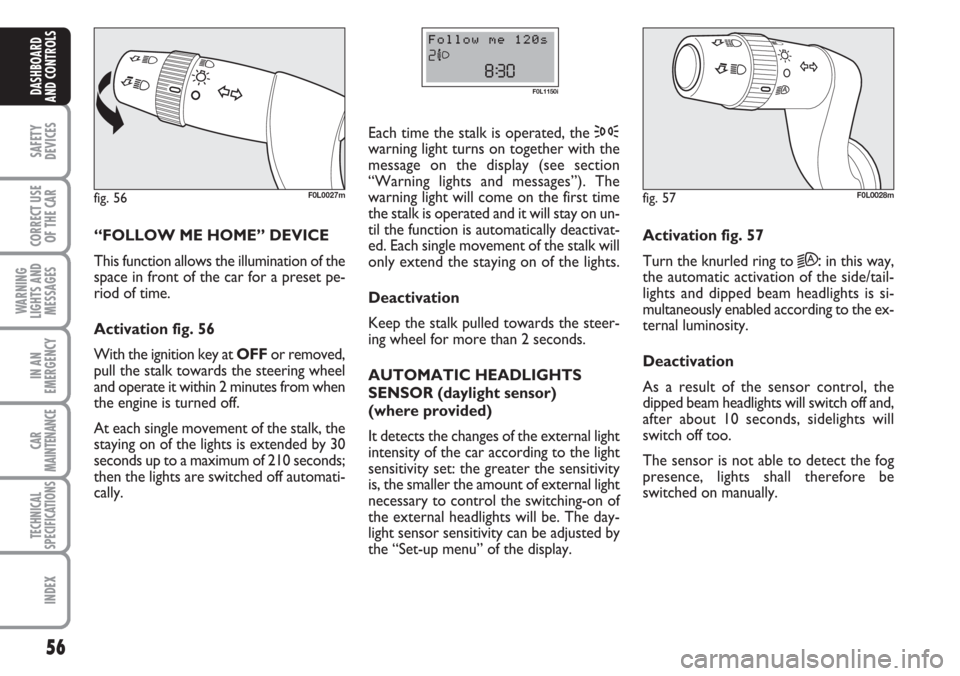
“FOLLOW ME HOME” DEVICE
This function allows the illumination of the
space in front of the car for a preset pe-
riod of time.
Activation fig. 56
With the ignition key at OFFor removed,
pull the stalk towards the steering wheel
and operate it within 2 minutes from when
the engine is turned off.
At each single movement of the stalk, the
staying on of the lights is extended by 30
seconds up to a maximum of 210 seconds;
then the lights are switched off automati-
cally. Each time the stalk is operated, the 3
warning light turns on together with the
message on the display (see section
“Warning lights and messages”). The
warning light will come on the first time
the stalk is operated and it will stay on un-
til the function is automatically deactivat-
ed. Each single movement of the stalk will
only extend the staying on of the lights.
Deactivation
Keep the stalk pulled towards the steer-
ing wheel for more than 2 seconds.
AUTOMATIC HEADLIGHTS
SENSOR (daylight sensor)
(where provided)
It detects the changes of the external light
intensity of the car according to the light
sensitivity set: the greater the sensitivity
is, the smaller the amount of external light
necessary to control the switching-on of
the external headlights will be. The day-
light sensor sensitivity can be adjusted by
the “Set-up menu” of the display.
fig. 56F0L0027m
F0L1150i
Activation fig. 57
Turn the knurled ring to
2A:in this way,
the automatic activation of the side/tail-
lights and dipped beam headlights is si-
multaneously enabled according to the ex-
ternal luminosity.
Deactivation
As a result of the sensor control, the
dipped beam headlights will switch off and,
after about 10 seconds, sidelights will
switch off too.
The sensor is not able to detect the fog
presence, lights shall therefore be
switched on manually.
fig. 57F0L0028m
Page 85 of 240
85
SAFETY
DEVICES
CORRECT USE
OF THE CAR
WARNING
LIGHTS AND
MESSAGES
IN AN
EMERGENCY
CAR
MAINTENANCE
TECHNICAL
SPECIFICATIONS
INDEX
DASHBOARD
AND CONTROLS
HEADLIGHTS
ADJUSTING THE HEADLIGHT
BEAM
Proper adjustment of the headlight beams
is of vital importance for your safety and
comfort and also for the other road users.
To ensure you and other drivers have the
best visibility conditions when travelling
with the headlights on, the headlights must
be set properly. Contact Fiat Dealership
to have the headlights properly adjusted.
IMPORTANT When turning on (Xenon)
gas discharge headlight lamps (where pro-
vided), it is normal that there should be a
vertical movement of reflectors, and con-
sequently the same will also happen to the
light beam, for the time required to
achieve the correct headlight trim stabili-
sation, equal to approx. 2 seconds.
Headlight aiming device
It works with ignition key at ONand
dipped beams on. When the car is loaded,
it slopes backwards. This means that the
headlight beam rises. In this case, it is nec-
essary to return it to the correct position.To adjust the headlight slant
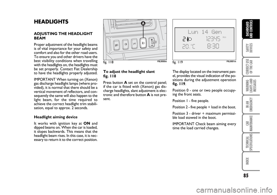
fig. 118
Press button Aset on the control panel;
if the car is fitted with (Xenon) gas dis-
charge headlights, slant adjustment is elec-
tronic and therefore button Ais not pre-
sent.The display located on the instrument pan-
el, provides the visual indication of the po-
sitions during the adjustment operation
fig. 119.
Position 0 - one or two people occupy-
ing the front seats.
Position 1 - five people.
Position 2 - five people + load in the boot.
Position 3 - driver + maximum permissi-
ble load stowed in the boot.
IMPORTANT Check beam aiming every
time the load carried changes.
fig. 118F0L0050mfig. 119F0L0051m
062-098 Croma TRW GB 20-11-2006 15:01 Pagina 85
Page 89 of 240
89
SAFETY
DEVICES
CORRECT USE
OF THE CAR
WARNING
LIGHTS AND
MESSAGES
IN AN
EMERGENCY
CAR
MAINTENANCE
TECHNICAL
SPECIFICATIONS
INDEX
DASHBOARD
AND CONTROLS
ASR SYSTEM
(AntiSlip Regulator)
(where provided)
The ASR function controls car drive and
cuts in automatically every time one or
both driving wheels slip.
According to slipping conditions, two dif-
ferent control systems are activated:
❒if slipping involves both driving wheels,
the ASR function intervenes reducing
the power transmitted by the engine;
❒if slipping involves only one driving
wheel, the TC (Traction Control)
function cuts in automatically braking
the wheel that is slipping.
The action of the ASR is particularly help-
ful in the following circumstances:
❒slipping of the inner wheel due to the
effect of dynamic load changes or ex-
cessive acceleration;
❒too much power transmitted to the
wheels also in relation to the condi-
tions of the road surface;
❒acceleration on slippery, snowy or
frozen surfaces;
❒in the case of loss of grip on a wet sur-
face (aquaplaning).
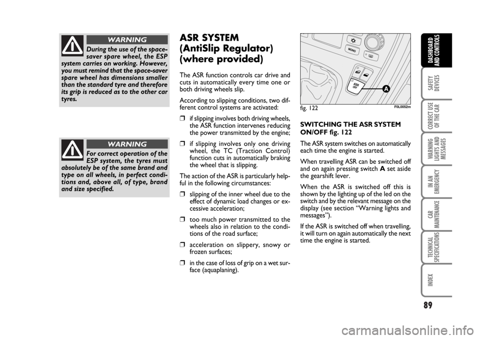
SWITCHING THE ASR SYSTEM
ON/OFF fig. 122
The ASR system switches on automatically
each time the engine is started.
When travelling ASR can be switched off
and on again pressing switchAset aside
the gearshift lever.
When the ASR is switched off this is
shown by the lighting up of the led on the
switch and by the relevant message on the
display (see section “Warning lights and
messages”).
If the ASR is switched off when travelling,
it will turn on again automatically the next
time the engine is started.
During the use of the space-
saver spare wheel, the ESP
system carries on working. However,
you must remind that the space-saver
spare wheel has dimensions smaller
than the standard tyre and therefore
its grip is reduced as to the other car
tyres.
WARNING
For correct operation of the
ESP system, the tyres must
absolutely be of the same brand and
type on all wheels, in perfect condi-
tions and, above all, of type, brand
and size specified.
WARNING
fig. 122F0L0052m
062-098 Croma TRW GB 20-11-2006 15:01 Pagina 89
Page 104 of 240
104
CORRECT USE
OF THE CAR
WARNING
LIGHTS AND
MESSAGES
IN AN
EMERGENCY
CAR
MAINTENANCE
TECHNICAL
SPECIFICATIONS
INDEX
DASHBOARD
AND CONTROLS
SAFETY
DEVICES
HOW TO KEEP THE SEAT
BELTS ALWAYS IN EFFICIENT
CONDITIONS
❒Always use the belt with the tape taut
and never twisted; make sure that it is
free to run without impediments.
❒After a serious accident, replace the
belt being worn at that time, even if
it does not appear damaged. Always
replace the seat belts if pretensioners
have been activated.
❒To clean the belts, wash by hand with
neutral soap, rinse and leave to dry in
the shade. Never use strong deter-
gents, bleach or dyes or other chem-
ical substance that might weaken the
fibres.
❒Prevent the reels from getting wet:
their correct operation is only guar-
anteed if water does not get inside.
❒Replace the seat belt when showing
significant wear or cut signs.
CARRYING CHILDREN
SAFELY
For optimal protection in the event of a
crash, all passengers must be seated and
wearing adequate restraint systems.
This is even more important for children.
This prescription is compulsory in all EC
countries according to EC Directive
2003/20/EC.
Compared with adults, their head is pro-
portionally larger and heavier than the rest
of the body, while the muscles and bone
structure are not completely developed.
Therefore, correct restraint systems are
necessary, other than adult seat belts. The
results of research on the best child re-
straint systems are contained in the Euro-
pean Standard EEC-R44. This Standard en-
forces the use of restraint systems classi-
fied in five groups:
Group 0 - 0-10 kg in weight
Group 0+ - 0-13 kg in weight
Group 1 9-18 kg in weight
Group 2 15-25 kg in weight
Group 3 22-36 kg in weight
If the belt has been subject-
ed to heavy stress, for ex-
ample after and accident, it should be
changed completely together with
the anchors, anchor fastening screws
and the pretensioners. In fact, even if
the belt has no visible defects, it could
have lost its resilience.
WARNING
Never travel with a child sit-
ting on the passenger’s lap
with a single belt to protect them
both. Do not fasten other objects to
the body.
WARNING
Page 125 of 240
ELECTRONIC
AUTOMATIC
TRANSMISSION
The car may be fitted with 5-speed (petrol
versions) or 6-speed (Multijet versions)
automatic transmission with electronic
control. Gears are shifted automatically
according to instant car parameters of use
(speed and accelerator pedal position).
Gears can however be shifted manually us-
ing transmission in sequential mode.
IMPORTANT Read carefully the follow-
ing points to learn how to use the elec-
tronic automatic transmission right from
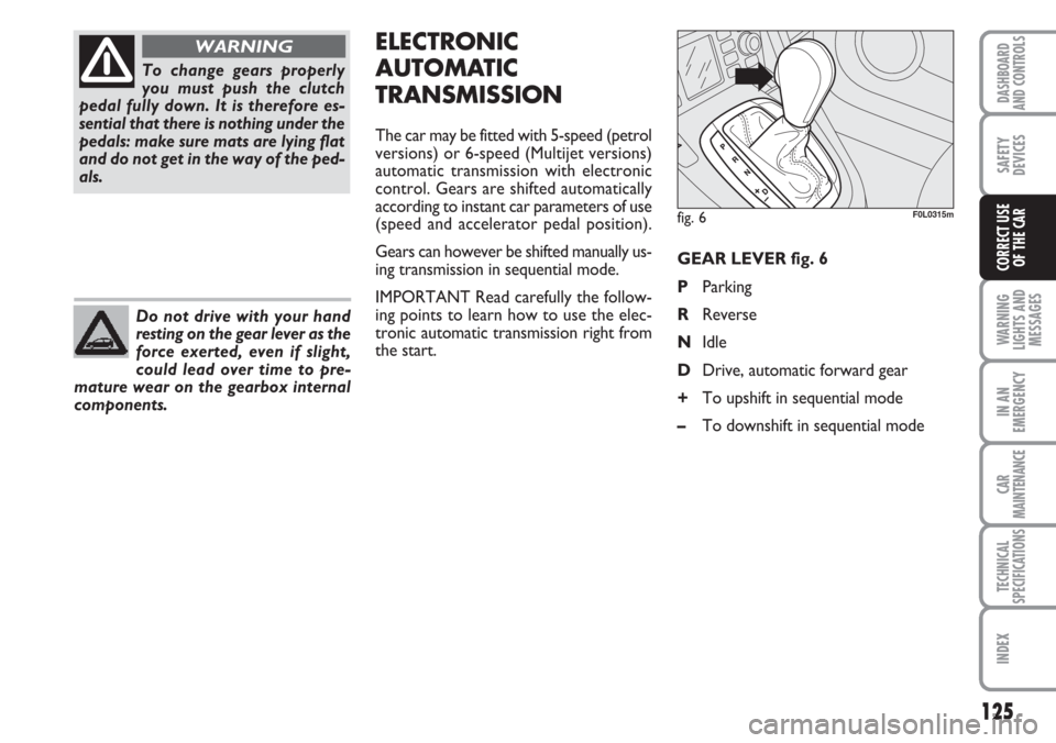
the start.GEAR LEVER fig. 6
PParking
RReverse
NIdle
DDrive, automatic forward gear
+To upshift in sequential mode
–To downshift in sequential mode
125
WARNING
LIGHTS AND
MESSAGES
IN AN
EMERGENCY
CAR
MAINTENANCE
TECHNICAL
SPECIFICATIONS
INDEX
DASHBOARD
AND CONTROLS
SAFETY
DEVICES
CORRECT USE
OF THE CAR
To change gears properly
you must push the clutch
pedal fully down. It is therefore es-
sential that there is nothing under the
pedals: make sure mats are lying flat
and do not get in the way of the ped-
als.
WARNING
Do not drive with your hand
resting on the gear lever as the
force exerted, even if slight,
could lead over time to pre-
mature wear on the gearbox internal
components.
fig. 6F0L0315m
Page 140 of 240
EXHAUST OIL
(Multijet versions)
The warning light with turn on
flashing together with the mes-
sage on the display when the system de-
tects that the engine oil is exhaust.
After the first indication, at each engine
starting the warning light
vwill go on
flashing for 60 seconds and then for 2
hours until oil is changed.
140
IN AN
EMERGENCY
CAR
MAINTENANCE
TECHNICAL
SPECIFICATIONS
INDEX
DASHBOARD
AND CONTROLS
SAFETY
DEVICES
CORRECT USE
OF THE CAR
WARNING
LIGHTS AND
MESSAGES
❒Car heavy duty(e.g.: towing trailer
uphill of fully laden car): decrease
speed, if the warning light stays on,
stop the car. Wait for 2 or 3 minutes
leaving the engine on and slightly ac-
celerated to further activate the cir-
culation of the coolant fluid, then
switch the engine off. Check proper
coolant level as described previously.
IMPORTANT Under severe use of the
car, keep the engine on and slightly accel-
erated for few minutes before switching it
off.
The display will show the dedicated mes-
sage.
LOW BATTERY
CHARGE (red)
Turning the key to ONthe
warning light turns on, but it should go out
as soon as the engine is started (with the
engine running at idle speed a brief delay
in going out is allowed).
If the warning light stays on contact im-
mediately Fiat Dealership.
w
INEFFICIENT ABS
SYSTEM (amber)
Turning the key to ONthe
warning light turns on, but it should go off
after few seconds.
The warning light turns on when the sys-
tem is inefficient or unavailable. In this case
the braking system keeps its effectiveness
unchanged, but without the potential of-
fered by the ABS system. Caution is ad-
visable and it is necessary to contact Fiat
Dealership.
The display will show the dedicated mes-
sage.
>
INEFFICIENT
EBD
ELECTRONIC
BRAKING
DISTRIBUTOR (red) (amber)
The turning on at the same time of warn-
ing lights
xand >with the engine run-
ning indicates an EBD system failure or
that the system is unavailable; in this case
heavy braking may cause the rear wheels
to lock before time, with the possibility of
skidding. Drive with the utmost care to
the nearest Fiat Dealership to have the
system checked.
The display will show the dedicated mes-
sage.
x>
LOW ENGINE OIL
PRESSURE (red)
Turning the ignition key to ON
the warning light turns on, but it should go
off after few seconds.
The display will show the dedicated mes-
sage.
v
v
If the warning light vturns on when travelling to-
gether with the message on the dis-
play, stop the engine immediately
and contact a Fiat Dealership.
WARNING
Page 155 of 240
155
WARNING
LIGHTS AND
MESSAGES
CAR
MAINTENANCE
TECHNICAL
SPECIFICATIONS
INDEX
DASHBOARD
AND CONTROLS
SAFETY
DEVICES
CORRECT USE
OF THE CAR
IN AN
EMERGENCY
❒Make sure the contact surfaces
between spare wheel and hub are
clean so that the fastening bolts will
not come loose;
❒Using the wrench provided, fully tigh-
ten the five fastening bolts;
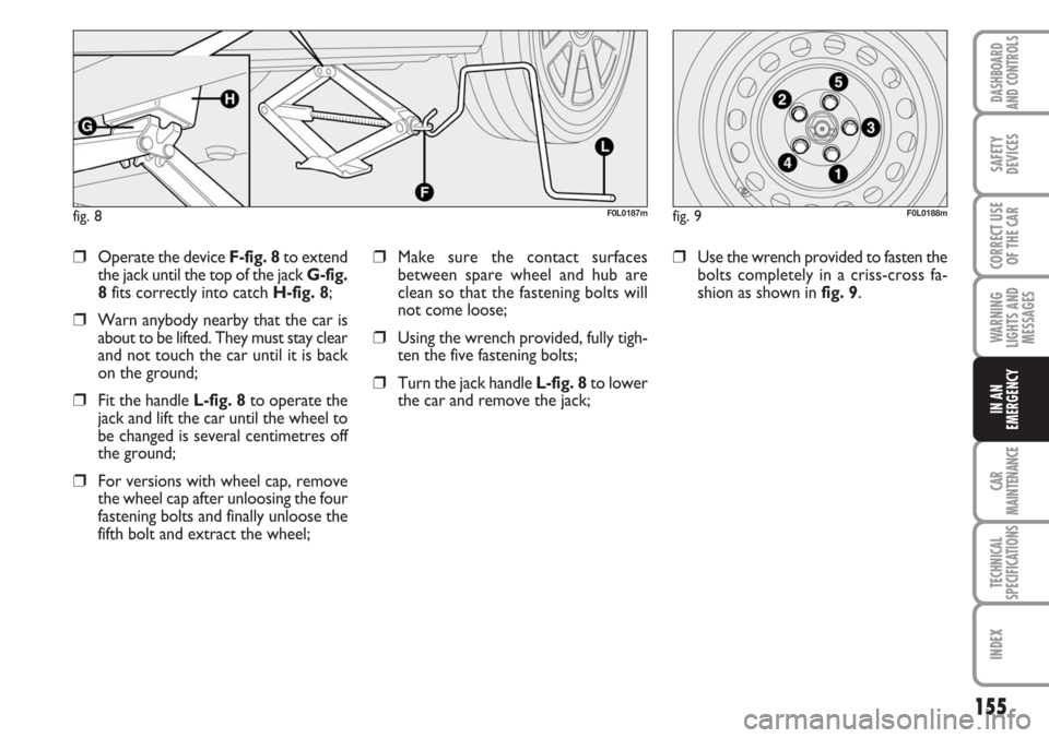
❒Turn the jack handle L-fig. 8to lower
the car and remove the jack;
❒Use the wrench provided to fasten the
bolts completely in a criss-cross fa-
shion as shown in fig. 9.❒Operate the device F-fig. 8to extend
the jack until the top of the jack G-fig.
8fits correctly into catch H-fig. 8;
❒Warn anybody nearby that the car is
about to be lifted. They must stay clear
and not touch the car until it is back
on the ground;
❒Fit the handle L-fig. 8to operate the
jack and lift the car until the wheel to
be changed is several centimetres off
the ground;
❒For versions with wheel cap, remove
the wheel cap after unloosing the four
fastening bolts and finally unloose the
fifth bolt and extract the wheel;
fig. 8F0L0187mfig. 9F0L0188m