fuse FIAT CROMA 2006 2.G Owners Manual
[x] Cancel search | Manufacturer: FIAT, Model Year: 2006, Model line: CROMA, Model: FIAT CROMA 2006 2.GPages: 240, PDF Size: 7.41 MB
Page 61 of 240
61
SAFETY
DEVICES
CORRECT USE
OF THE CAR
WARNING
LIGHTS AND
MESSAGES
IN AN
EMERGENCY
CAR
MAINTENANCE
TECHNICAL
SPECIFICATIONS
INDEX
DASHBOARD
AND CONTROLS
TO INCREASE THE MEMORISED
SPEED
The speed memorised can be increased in
two ways:
❒pressing the accelerator and then
memorising the new speed reached;
or
❒moving the stalk upwards (+).
Each operation of the stalk will corre-
spond to a slight increase in speed (about
1 km/h), while keeping the stalk upwards
will correspond to a continuous speed in-
crease.
TO REDUCE MEMORISED
SPEED
The speed memorised can be increased in
two ways:
❒disengaging the device and then mem-
orising the new speed;
or
❒moving the stalk downwards (–) until
reaching the new speed which will be
memorised automatically.
Each operation of the stalk will corre-
spond to a slight reduction in speed (about
1 km/h), while keeping the stalk down-
wards will correspond to a continuous
speed reduction.DEVICE DISENGAGEMENT
The device can be disengaged in the fol-
lowing ways:
❒turning the knurled ring Ato OFF;
❒turning the engine off;
❒pressing the brake pedal or engaging
the hand brake;
❒pressing the clutch pedal;
❒shifting gear with automatic transmis-
sion in sequential mode;
❒with car speed below the preset lim-
it;
❒pressing the accelerator pedal; in this
case the system is not really disen-
gaged but the request for acceleration
takes priority over the system. The
cruise control is however active and it
will not be necessary to press button
RES to resume previous conditions
after ending acceleration.The device is automatically deactivated in
one of the following cases:
❒ABS or ESP system cut-in;
❒system failure.
When travelling with the de-
vice on, never set the
gearshift lever to neutral.
WARNING
In the event of device mal-
function or failure, turn the
knurled ring A to OFF and contact a
Fiat Dealership after checking the
protection fuse integrity.
WARNING
Page 65 of 240
65
SAFETY
DEVICES
CORRECT USE
OF THE CAR
WARNING
LIGHTS AND
MESSAGES
IN AN
EMERGENCY
CAR
MAINTENANCE
TECHNICAL
SPECIFICATIONS
INDEX
DASHBOARD
AND CONTROLS
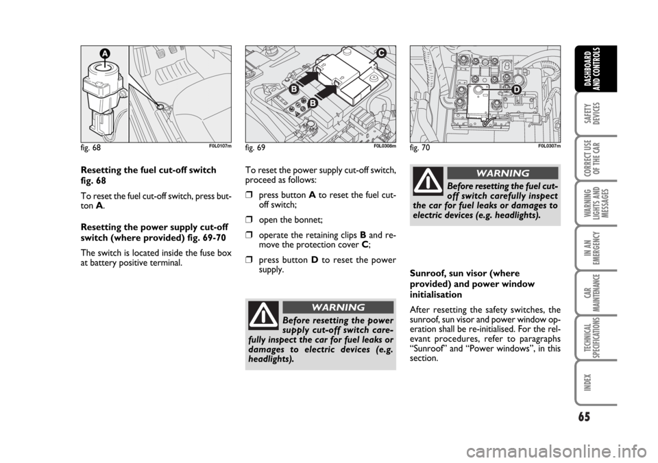
Resetting the fuel cut-off switch
fig. 68
To reset the fuel cut-off switch, press but-
ton A.
Resetting the power supply cut-off
switch (where provided) fig. 69-70
The switch is located inside the fuse box
at battery positive terminal.To reset the power supply cut-off switch,
proceed as follows:
❒press button Ato reset the fuel cut-
off switch;
❒open the bonnet;
❒operate the retaining clips Band re-
move the protection cover C;
❒press button Dto reset the power
supply.
fig. 68F0L0107mfig. 69F0L0308mfig. 70F0L0307m
Before resetting the power
supply cut-off switch care-
fully inspect the car for fuel leaks or
damages to electric devices (e.g.
headlights).
WARNING
Before resetting the fuel cut-
off switch carefully inspect
the car for fuel leaks or damages to
electric devices (e.g. headlights).
WARNING
Sunroof, sun visor (where
provided) and power window
initialisation
After resetting the safety switches, the
sunroof, sun visor and power window op-
eration shall be re-initialised. For the rel-
evant procedures, refer to paragraphs
“Sunroof” and “Power windows”, in this
section.
062-098 Croma TRW GB 20-11-2006 15:01 Pagina 65
Page 71 of 240
71
SAFETY
DEVICES
CORRECT USE
OF THE CAR
WARNING
LIGHTS AND
MESSAGES
IN AN
EMERGENCY
CAR
MAINTENANCE
TECHNICAL
SPECIFICATIONS
INDEX
DASHBOARD
AND CONTROLS
Front sun curtain opening/closing
Press button B-fig. 86to open the sun
curtain fully. Press the button again to stop
it.
To close the sun curtain press button C-
fig. 86. Press the button again to stop it.
Caution: opening the sunroof with the sun
curtain closed will make the sun curtain
open automatically.
Rear sun curtain opening/closing
Rear sun curtain opening/closing is man-
ual.ANTI-CRUSHING SAFETY
SYSTEM
Sunroof is fitted with anti-crushing safety
system that detects the presence of an ob-
stacle during sunroof closing stroke and
that cuts in by stopping and reversing the
sunroof stroke.
The anti-crushing safety system fitted on
the front curtain outline is active along the
whole closing range of the curtain and cuts
into operation when an obstacle is met.
This safety device guarantees the rever-
sal for a short section.
INITIALISATION PROCEDURE
Sunroof and powered sun curtain shall be
re-initialised after disconnecting the bat-
tery or if the relevant protection fuse is
blown.Sunroof initialisation
Proceed as follows:
❒turn the ignition key to ON;
❒turn knob A-fig. 86fully counter-
clockwise;
❒press and keep knob A-fig. 86
pressed until the sunroof locks, then
release it;
❒within 5 seconds, press and keep knob
A pressed; the sunroof will move au-
tomatically, during this stage keep on
pressing the knob;
❒initialisation will end when the sunroof
stops.
When leaving the car, the ig-
nition key should be removed
to prevent the sunroof from being op-
erated inadvertently and harming any-
one remaining in the car. Improper use
of the sunroof can be dangerous. Be-
fore and during its operation ensure
that any passengers are not at risk
from the moving roof either by per-
sonal objects getting caught in the
mechanism or by being injured by it di-
rectly.
WARNING
062-098 Croma TRW GB 20-11-2006 15:01 Pagina 71
Page 74 of 240
74
SAFETY
DEVICES
CORRECT USE
OF THE CAR
WARNING
LIGHTS AND
MESSAGES
IN AN
EMERGENCY
CAR
MAINTENANCE
TECHNICAL
SPECIFICATIONS
INDEX
DASHBOARD
AND CONTROLS
POWER WINDOWS
All versions are fitted with power win-
dows with anti-crushing safety device to
detect the presence of an obstacle in the
window closing stroke. If an obstacle is de-
tected, the safety system will stop window
closing and, according to window position,
will also reverse window stroke.
IMPORTANT In the event that the anti-
crushing function is activated 5 times in
only 1 minute, the system will automati-
cally enter the “recovery” mode (self-pro-
tection). This conditions is pointed out by
the fact that, in the closing phase, the win-
dow goes up in jerks.
So, it is necessary to carry out the sys-
tem restore procedure, acting as follows:
❒open the windows;
or
❒turn the ignition key to OFFand then
to ON.
The logic is restored if no malfunction is
present, the window returns to its normal
operation automatically; otherwise con-
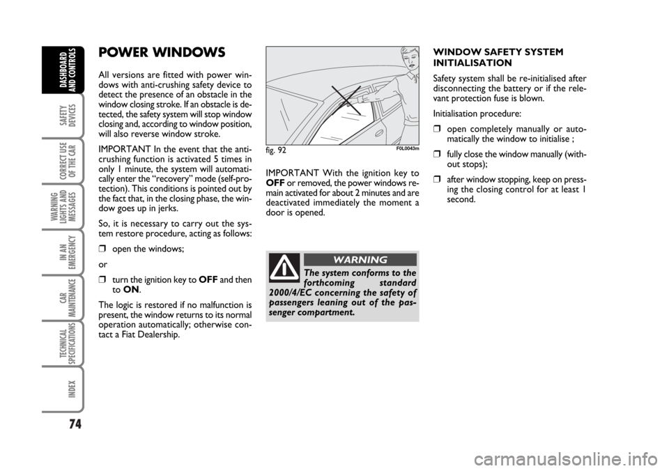
tact a Fiat Dealership.IMPORTANT With the ignition key to
OFFor removed, the power windows re-
main activated for about 2 minutes and are
deactivated immediately the moment a
door is opened.WINDOW SAFETY SYSTEM
INITIALISATION
Safety system shall be re-initialised after
disconnecting the battery or if the rele-
vant protection fuse is blown.
Initialisation procedure:
❒open completely manually or auto-
matically the window to initialise ;
❒fully close the window manually (with-
out stops);
❒after window stopping, keep on press-
ing the closing control for at least 1
second.
fig. 92F0L0043m
The system conforms to the
forthcoming standard
2000/4/EC concerning the safety of
passengers leaning out of the pas-
senger compartment.
WARNING
062-098 Croma TRW GB 20-11-2006 15:01 Pagina 74
Page 93 of 240
93
SAFETY
DEVICES
CORRECT USE
OF THE CAR
WARNING
LIGHTS AND
MESSAGES
IN AN
EMERGENCY
CAR
MAINTENANCE
TECHNICAL
SPECIFICATIONS
INDEX
DASHBOARD
AND CONTROLS
Hi-Fi system (where provided)
The system includes:
❒2 tweeters (power 40W max. each),
located on front doors;
❒2 mid-woofers (diameter 165 mm,
power 40W each), located on front
doors;
❒2 tweeters (power 40W each), locat-
ed on rear doors;
❒2 woofers (diameter 165 mm, power
40W max. each), located on rear
doors;
❒1 subwoofer (100W power), located
on the right side of the boot. Sub-
woofer is protected by 10A fuse.
ACCESSORIES
PURCHASED BY THE
OWNER
If after buying the vehicle, you decide to
install electrical accessories that require a
permanent electric supply (alarm, satellite
antitheft system, etc.) or accessories that
in any case burden the electric supply,
contact Fiat Dealership, whose qualified
personnel, besides suggesting the most
suitable devices belonging to Lineaccessori
Fiat, will also evaluate the overall electric
absorption, checking whether the vehicle
electric system is able to withstand the
load required, or whether it needs to be
integrated with a more powerful battery.
INSTALLATION OF
ELECTRIC/ELECTRONIC
DEVICES
Electric/electronic devices installed after
buying the vehicle and in after-market shall
bear the following marking:
Fiat Auto S.p.A. authorizes the installation
of transceivers, provided that installation
is workmanlike performed in compliance
with Manufacturer’s specifications at a spe-
cialised service centre.
IMPORTANT The installation of devices
involving modifications of vehicle charac-
teristics may determine the withdrawal ofthe driving licence by the appointed pub-
lic authorities and the forfeiture of the
warranty as concerns defects/failures due
to said modification or leading directly or
indirectly to it.
Fiat Auto S.p.A. declines all responsibility
due to damages connected with the in-
stallation of accessories/devices not sup-
plied by or recommended by Fiat Auto
S.p.A. and installed not in compliance with
the specified prescriptions.
RADIO TRANSMITTERS
AND CELLULAR TELEPHONES
Radio transceiver equipment (e.g.: e-tacs
mobile phones, HAM radio systems and
the like) shall not be used inside the ve-
hicle unless a separate aerial is mounted
on the roof.
IMPORTANT The use of similar devices
inside the passenger compartment (with-
out separated aerial) produces radio-fre-
quency electromagnetic fields which, am-
plified by the resonance effects inside the
passenger compartment, may cause elec-
trical systems equipping the vehicle to mal-
function. This could compromise safety in
addition to constituting a potential hazard
for the passengers.
In addition, transmission and reception of
these devices may be affected by the
shielding effect of the vehicle body.
As concerns EC-approved mobile phones
(GSM, GPRS, UMTS), strictly comply with
the instructions for use provided by the
mobile phone’s manufacturer.
062-098 Croma TRW GB 20-11-2006 15:01 Pagina 93
Page 144 of 240
Warning light vturns on
together with the dedicated
message on the display to in-
dicate that the cleaning pro-
cedure cannot be performed, contact
Fiat Dealership as soon as possible.
144
IN AN
EMERGENCY
CAR
MAINTENANCE
TECHNICAL
SPECIFICATIONS
INDEX
DASHBOARD
AND CONTROLS
SAFETY
DEVICES
CORRECT USE
OF THE CAR
WARNING
LIGHTS AND
MESSAGES
GENERIC FAILURE
INDICATION
(amber)
The warning light turns on in the follow-
ing circumstances.
Engine oil pressure
sensor failure
The warning light comes on when the en-
gine oil pressure sensor is faulty. Contact
Fiat Dealership as soon as possible.
The display will show the dedicated mes-
sage.
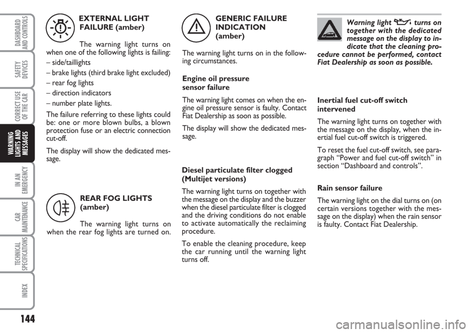
è
EXTERNAL LIGHT
FAILURE (amber)
The warning light turns on
when one of the following lights is failing:
– side/taillights
– brake lights (third brake light excluded)
– rear fog lights
– direction indicators
– number plate lights.
The failure referring to these lights could
be: one or more blown bulbs, a blown
protection fuse or an electric connection
cut-off.
The display will show the dedicated mes-
sage.
W
REAR FOG LIGHTS
(amber)
The warning light turns on
when the rear fog lights are turned on.
4
Diesel particulate filter clogged
(Multijet versions)
The warning light turns on together with
the message on the display and the buzzer
when the diesel particulate filter is clogged
and the driving conditions do not enable
to activate automatically the reclaiming
procedure.
To enable the cleaning procedure, keep
the car running until the warning light
turns off.
Inertial fuel cut-off switch
intervened
The warning light turns on together with
the message on the display, when the in-
ertial fuel cut-off switch is triggered.
To reset the fuel cut-off switch, see para-
graph “Power and fuel cut-off switch” in
section “Dashboard and controls”.
Rain sensor failure
The warning light on the dial turns on (on
certain versions together with the mes-
sage on the display) when the rain sensor
is faulty. Contact Fiat Dealership.
Page 149 of 240

149
WARNING
LIGHTS AND
MESSAGES
CAR
MAINTENANCE
TECHNICAL
SPECIFICATIONS
INDEX
DASHBOARD
AND CONTROLS
SAFETY
DEVICES
CORRECT USE
OF THE CAR
IN AN
EMERGENCY
JUMP STARTING .................................................................... 150
BUMP STARTING .................................................................. 151
IF A TYRE IS PUNCTURED ................................................ 151
WHEN NEEDING TO CHANGE A BULB .................... 157
IF AN EXTERIOR LIGHT BURNS OUT .......................... 161
IF AN INTERIOR LIGHT BURNS OUT ........................... 166
IF A FUSE BLOWS ................................................................. 169
IF THE BATTERY IS FLAT ................................................... 180
JACKING THE CAR .............................................................. 180
TOWING THE CAR ............................................................ 181
I I
N N
A A
N N
E E
M M
E E
R R
G G
E E
N N
C C
Y Y
Page 157 of 240
157
WARNING
LIGHTS AND
MESSAGES
CAR
MAINTENANCE
TECHNICAL
SPECIFICATIONS
INDEX
DASHBOARD
AND CONTROLS
SAFETY
DEVICES
CORRECT USE
OF THE CAR
IN AN
EMERGENCY
WHEN NEEDING TO
CHANGE A BULB
GENERAL INSTRUCTIONS
❒When a light is not working, check
that the corresponding fuse is intact
before changing a bulb. For the loca-
tion of fuses, refer to the paragraph “If
a fuse blows” in this section;
❒Before changing a bulb check the con-
tacts for oxidation;
❒Burnt bulbs must be replaced by
others of the same type and power;
❒Always check the height of the head-
light beam after changing a bulb.
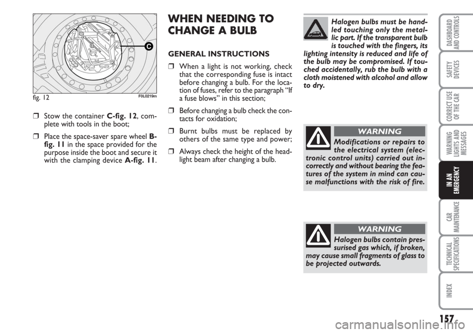
❒Stow the container C-fig. 12, com-
plete with tools in the boot;
❒Place the space-saver spare wheel B-
fig. 11in the space provided for the
purpose inside the boot and secure it
with the clamping device A-fig. 11.
fig. 12F0L0219m
Halogen bulbs must be hand-
led touching only the metal-
lic part. If the transparent bulb
is touched with the fingers, its
lighting intensity is reduced and life of
the bulb may be compromised. If tou-
ched accidentally, rub the bulb with a
cloth moistened with alcohol and allow
to dry.
Modifications or repairs to
the electrical system (elec-
tronic control units) carried out in-
correctly and without bearing the fea-
tures of the system in mind can cau-
se malfunctions with the risk of fire.
WARNING
Halogen bulbs contain pres-
surised gas which, if broken,
may cause small fragments of glass to
be projected outwards.
WARNING
Page 169 of 240
169
WARNING
LIGHTS AND
MESSAGES
CAR
MAINTENANCE
TECHNICAL
SPECIFICATIONS
INDEX
DASHBOARD
AND CONTROLS
SAFETY
DEVICES
CORRECT USE
OF THE CAR
IN AN
EMERGENCY
IF A FUSE BLOWS
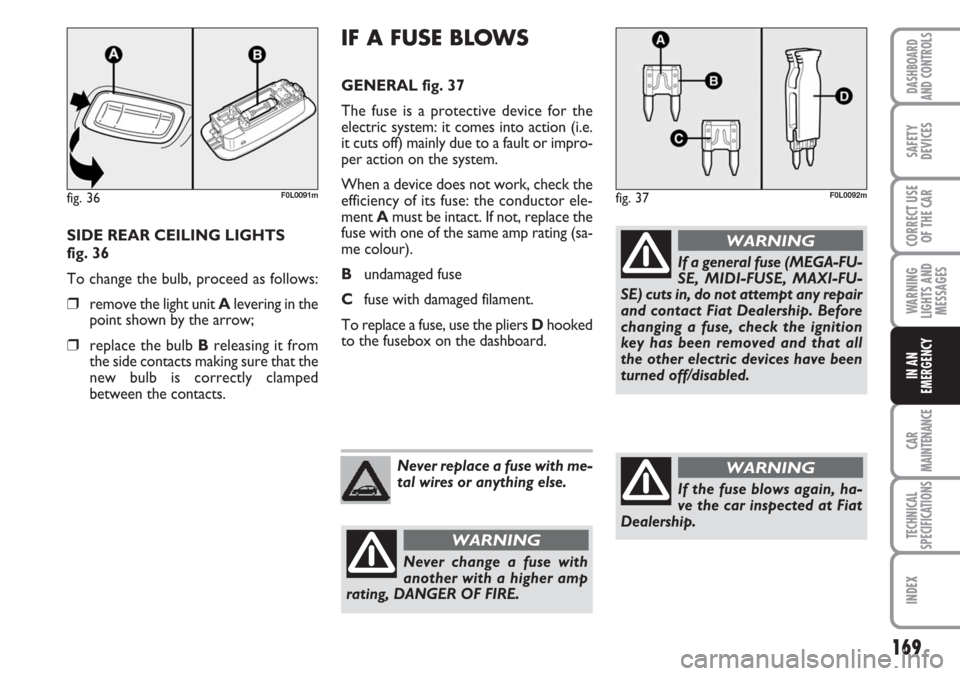
GENERAL fig. 37
The fuse is a protective device for the
electric system: it comes into action (i.e.
it cuts off) mainly due to a fault or impro-
per action on the system.
When a device does not work, check the
efficiency of its fuse: the conductor ele-
ment Amust be intact. If not, replace the
fuse with one of the same amp rating (sa-
me colour).
Bundamaged fuse
Cfuse with damaged filament.
To replace a fuse, use the pliers Dhooked
to the fusebox on the dashboard. SIDE REAR CEILING LIGHTS
fig. 36
To change the bulb, proceed as follows:
❒remove the light unit Alevering in the
point shown by the arrow;
❒replace the bulb Breleasing it from
the side contacts making sure that the
new bulb is correctly clamped
between the contacts.
fig. 36F0L0091mfig. 37F0L0092m
Never replace a fuse with me-
tal wires or anything else.
Never change a fuse with
another with a higher amp
rating, DANGER OF FIRE.
WARNING
If a general fuse (MEGA-FU-
SE, MIDI-FUSE, MAXI-FU-
SE) cuts in, do not attempt any repair
and contact Fiat Dealership. Before
changing a fuse, check the ignition
key has been removed and that all
the other electric devices have been
turned off/disabled.
WARNING
If the fuse blows again, ha-
ve the car inspected at Fiat
Dealership.
WARNING
Page 170 of 240
170
WARNING
LIGHTS AND
MESSAGES
CAR
MAINTENANCE
TECHNICAL
SPECIFICATIONS
INDEX
DASHBOARD
AND CONTROLS
SAFETY
DEVICES
CORRECT USE
OF THE CAR
IN AN
EMERGENCY
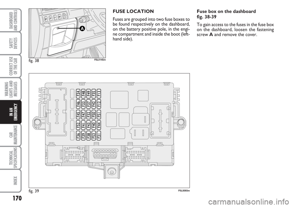
FUSE LOCATION
Fuses are grouped into two fuse boxes to
be found respectively on the dashboard,
on the battery positive pole, in the engi-
ne compartment and inside the boot (left-
hand side).
fig. 38
fig. 39F0L0145m
F0L0093m
Fuse box on the dashboard
fig. 38-39
To gain access to the fuses in the fuse box
on the dashboard, loosen the fastening
screw Aand remove the cover.