door lock FIAT DOBLO COMBI 2012 Owner handbook (in English)
[x] Cancel search | Manufacturer: FIAT, Model Year: 2012, Model line: DOBLO COMBI, Model: FIAT DOBLO COMBI 2012Pages: 283, PDF Size: 6.31 MB
Page 83 of 283
79
KNOW
YOUR
VEHICLE
SAFETY
STARTING
AND
DRIVING
WARNING
LIGHTS AND
MESSAGES
IN AN
EMERGENCY
SERVICING
AND
MAINTENANCE
TECHNICAL
SPECIFICATIONS
INDEX
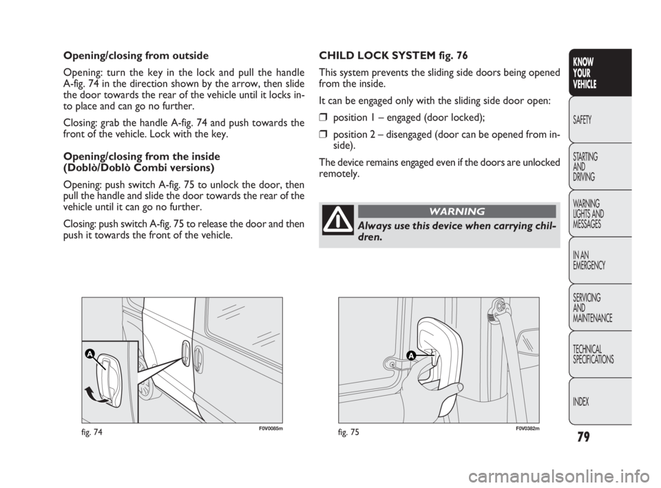
F0V0085mfig. 74F0V0382mfig. 75
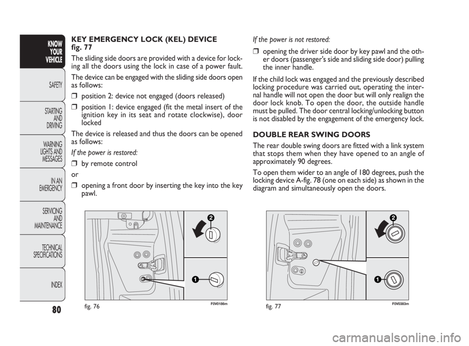
CHILD LOCK SYSTEM fig. 76
This system prevents the sliding side doors being opened
from the inside.
It can be engaged only with the sliding side door open:
❒position 1 – engaged (door locked);
❒position 2 – disengaged (door can be opened from in-
side).
The device remains engaged even if the doors are unlocked
remotely. Opening/closing from outside
Opening: turn the key in the lock and pull the handle
A-fig. 74 in the direction shown by the arrow, then slide
the door towards the rear of the vehicle until it locks in-
to place and can go no further.
Closing: grab the handle A-fig. 74 and push towards the
front of the vehicle. Lock with the key.
Opening/closing from the inside
(Doblò/Doblò Combi versions)
Opening: push switch A-fig. 75 to unlock the door, then
pull the handle and slide the door towards the rear of the
vehicle until it can go no further.
Closing: push switch A-fig. 75 to release the door and then
push it towards the front of the vehicle.
Always use this device when carrying chil-
dren.
WARNING
035-114 DOBLO LUM EN 1ed 6-02-2012 9:39 Pagina 79
Page 84 of 283
80
KNOW
YOUR
VEHICLE
SAFETY
STARTING
AND
DRIVING
WARNING
LIGHTS AND
MESSAGES
IN AN
EMERGENCY
SERVICING
AND
MAINTENANCE
TECHNICAL
SPECIFICATIONS
INDEX
F0V0186mfig. 76
KEY EMERGENCY LOCK (KEL) DEVICE
fig. 77
The sliding side doors are provided with a device for lock-
ing all the doors using the lock in case of a power fault.
The device can be engaged with the sliding side doors open
as follows:
❒position 2: device not engaged (doors released)
❒position 1: device engaged (fit the metal insert of the
ignition key in its seat and rotate clockwise), door
locked
The device is released and thus the doors can be opened
as follows:
If the power is restored:
❒by remote control
or
❒opening a front door by inserting the key into the key
pawl.
F0V0383mfig. 77
If the power is not restored:
❒opening the driver side door by key pawl and the oth-
er doors (passenger's side and sliding side door) pulling
the inner handle.
If the child lock was engaged and the previously described
locking procedure was carried out, operating the inter-
nal handle will not open the door but will only realign the
door lock knob. To open the door, the outside handle
must be pulled. The door central locking/unlocking button
is not disabled by the engagement of the emergency lock.
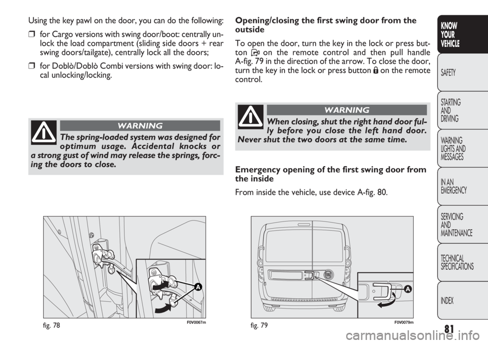
DOUBLE REAR SWING DOORS
The rear double swing doors are fitted with a link system
that stops them when they have opened to an angle of
approximately 90 degrees.
To open them wider to an angle of 180 degrees, push the
locking device A-fig. 78 (one on each side) as shown in the
diagram and simultaneously open the doors.
035-114 DOBLO LUM EN 1ed 6-02-2012 9:39 Pagina 80
Page 85 of 283
81
KNOW
YOUR
VEHICLE
SAFETY
STAR
TING
AND
DRIVING
WARNING
LIGHTS AND
MESSAGES
IN AN
EMERGENCY
SERVICING
AND
MAINTENANCE
TECHNICAL
SPECIFICATIONS
INDEX
F0V0067mfig. 78F0V0079mfig. 79
Opening/closing the first swing door from the
outside
To open the door, turn the key in the lock or press but-
ton Pon the remote control and then pull handle
A-fig. 79 in the direction of the arrow. To close the door,
turn the key in the lock or press button
Áon the remote
control.
Using the key pawl on the door, you can do the following:
❒for Cargo versions with swing door/boot: centrally un-
lock the load compartment (sliding side doors + rear
swing doors/tailgate), centrally lock all the doors;
❒for Doblò/Doblò Combi versions with swing door: lo-
cal unlocking/locking.
The spring-loaded system was designed for
optimum usage. Accidental knocks or
a strong gust of wind may release the springs, forc-
ing the doors to close.
WARNINGWhen closing, shut the right hand door ful-
ly before you close the left hand door.
Never shut the two doors at the same time.
WARNING
Emergency opening of the first swing door from
the inside
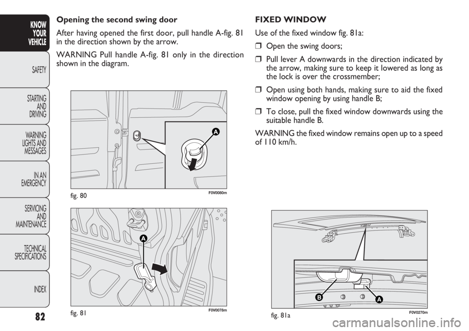
From inside the vehicle, use device A-fig. 80.
Page 86 of 283
82
KNOWYOUR
VEHICLE
SAFETY
ST AR
TING AND
DRIVING
WARNING
LIGHTS AND MESSAGES
IN AN
EMERGENCY
SERVICING AND
MAINTENANCE
TECHNICAL
SPECIFICATIONS
INDEX
F0V0078mfig. 81
F0V0080mfig. 80
Opening the second swing door
After having opened the first door, pull handle A-fig. 81
in the direction shown by the arrow.
WARNING Pull handle A-fig. 81 only in the direction
shown in the diagram.
AB
F0V0270mfig. 81a
FIXED WINDOW
Use of the fixed window fig. 81a:
❒Open the swing doors;
❒Pull lever A downwards in the direction indicated by
the arrow, making sure to keep it lowered as long as
the lock is over the crossmember;
❒Open using both hands, making sure to aid the fixed
window opening by using handle B;
❒To close, pull the fixed window downwards using the
suitable handle B.
WARNING the fixed window remains open up to a speed
of 110 km/h.
Page 89 of 283
85
KNOW
YOUR
VEHICLE
SAFETY
STAR
TING
AND
DRIVING
WARNING
LIGHTS AND
MESSAGES
IN AN
EMERGENCY
SERVICING
AND
MAINTENANCE
TECHNICAL
SPECIFICATIONS
INDEX
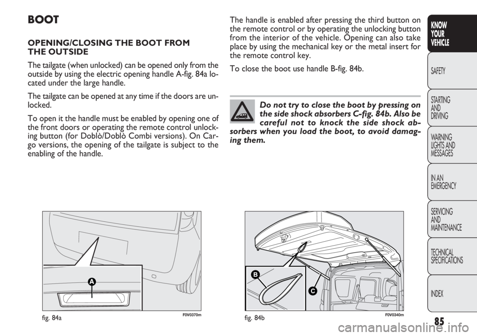
F0V0370mfig. 84a
BOOT
OPENING/CLOSING THE BOOT FROM
THE OUTSIDE
The tailgate (when unlocked) can be opened only from the
outside by using the electric opening handle A-fig. 84a lo-
cated under the large handle.
The tailgate can be opened at any time if the doors are un-
locked.
To open it the handle must be enabled by opening one of
the front doors or operating the remote control unlock-
ing button (for Doblò/Doblò Combi versions). On Car-
go versions, the opening of the tailgate is subject to the
enabling of the handle. The handle is enabled after pressing the third button on
the remote control or by operating the unlocking button
from the interior of the vehicle. Opening can also take
place by using the mechanical key or the metal insert for
the remote control key.
To close the boot use handle B-fig. 84b.
Do not try to close the boot by pressing on
the side shock absorbers C-fig. 84b. Also be
careful not to knock the side shock ab-
sorbers when you load the boot, to avoid damag-
ing them.
F0V0340mfig. 84b
Page 179 of 283
175
KNOW
YOUR
VEHICLE
SAFETY
STARTING
AND
DRIVING
WARNING
LIGHTS AND
MESSAGES
IN AN
EMERGENCY
SERVICING
AND
MAINTENANCE
TECHNICAL
SPECIFICATIONS
INDEXTo access bulbs A – B – D – F, loosen the four fastening
screws E-fig. 157 and extract the bulb holder. To change
the bulb, push it in gently and turn it anticlockwise (“bay-
onet” fixture), then remove and replace it.
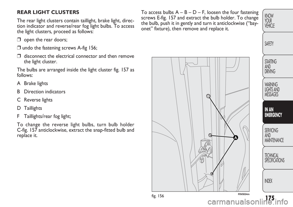
REAR LIGHT CLUSTERS
The rear light clusters contain taillight, brake light, direc-
tion indicator and reverse/rear fog light bulbs. To access
the light clusters, proceed as follows:
❒
open the rear doors;
❒ undo the fastening screws A-fig 156;
❒ disconnect the electrical connector and then remove
the light cluster.
The bulbs are arranged inside the light cluster fig. 157 as
follows:
A Brake lights
B Direction indicators
C Reverse lights
D Taillights
F Taillights/rear fog light;
To change the reverse light bulbs, turn bulb holder
C-fig. 157 anticlockwise, extract the snap-fitted bulb and
replace it.
F0V0034mfig. 156
Page 181 of 283
177
KNOW
YOUR
VEHICLE
SAFETY
STARTING
AND
DRIVING
WARNING
LIGHTS AND
MESSAGES
IN AN
EMERGENCY
SERVICING
AND
MAINTENANCE
TECHNICAL
SPECIFICATIONS
INDEX
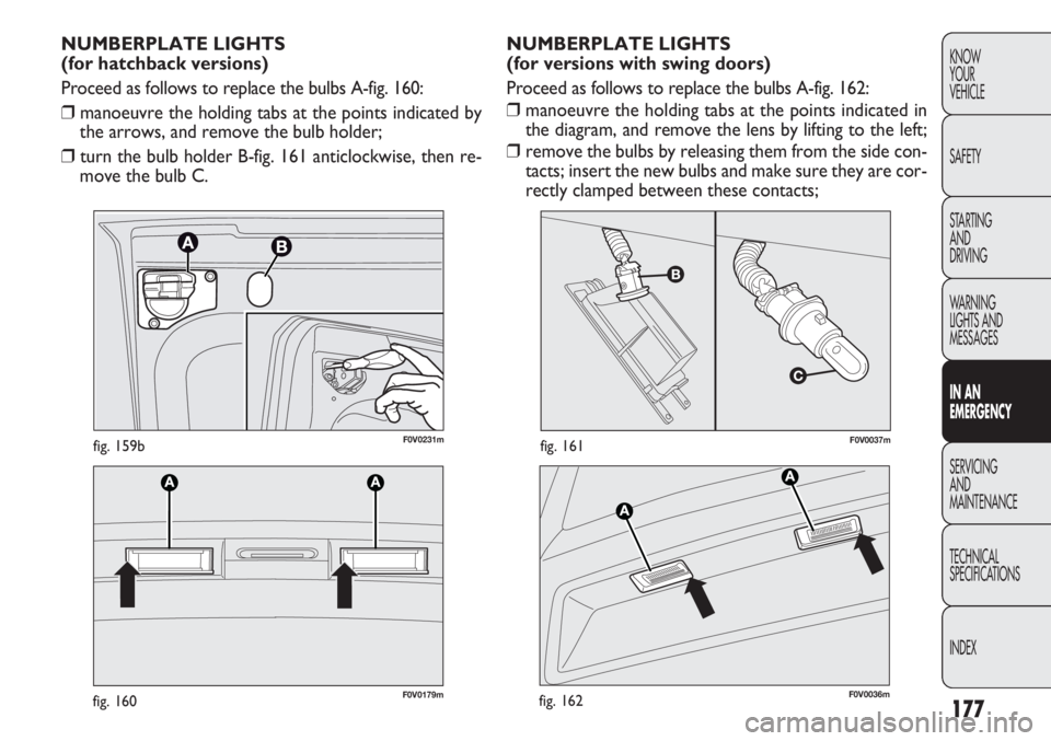
F0V0037mfig. 161
F0V0179mfig. 160
NUMBERPLATE LIGHTS
(for versions with swing doors)
Proceed as follows to replace the bulbs A-fig. 162:
❒ manoeuvre the holding tabs at the points indicated in
the diagram, and remove the lens by lifting to the left;
❒ remove the bulbs by releasing them from the side con-
tacts; insert the new bulbs and make sure they are cor-
rectly clamped between these contacts;
NUMBERPLATE LIGHTS
(for hatchback versions)
Proceed as follows to replace the bulbs A-fig. 160:
❒
manoeuvre the holding tabs at the points indicated by
the arrows, and remove the bulb holder;
❒ turn the bulb holder B-fig. 161 anticlockwise, then re-
move the bulb C.
F0V0036mfig. 162
F0V0231mfig. 159b
Page 189 of 283
185
KNOW
YOUR
VEHICLE
SAFETY
STARTING
AND
DRIVING
WARNING
LIGHTS AND
MESSAGES
IN AN
EMERGENCY
SERVICING
AND
MAINTENANCE
TECHNICAL
SPECIFICATIONS
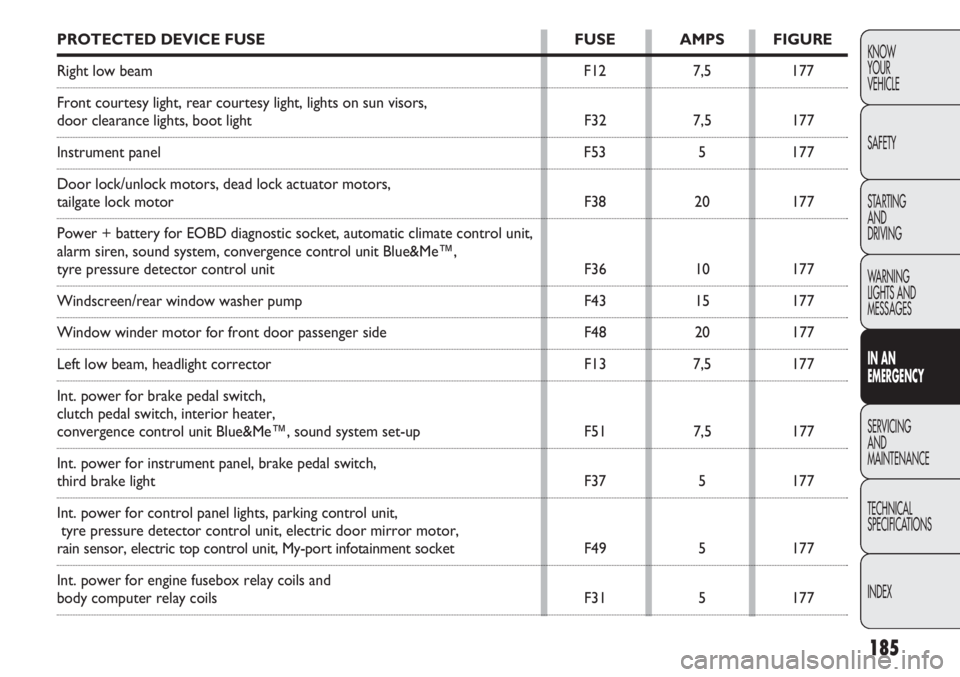
INDEXPROTECTED DEVICE FUSE FUSE AMPS FIGURE
Right low beam F127,5177
Front courtesy light, rear courtesy light, lights on sun visors,
door clearance lights, boot light F327,5177
Instrument panel F535177
Door lock/unlock motors, dead lock actuator motors,
tailgate lock motor F3820177
Power + battery for EOBD diagnostic socket, automatic climate control un\
it,
alarm siren, sound system, convergence control unit Blue&Me™,
tyre pressure detector control unit F3610177
Windscreen/rear window washer pump F4315177
Window winder motor for front door passenger side F4820177
Left low beam, headlight corrector F137,5177
Int. power for brake pedal switch,
clutch pedal switch, interior heater,
convergence control unit Blue&Me™, sound system set-up F517,5177
Int. power for instrument panel, brake pedal switch,
third brake light F375177
Int. power for control panel lights, parking control unit, tyre pressure detector control unit, electric door mirror motor,
rain sensor, electric top control unit, My-port infotainment socket F495177
Int. power for engine fusebox relay coils and
body computer relay coils F315177
Page 273 of 283
269
KNOW
YOUR
VEHICLE
SAFETY
STARTING
AND
DRIVING
WARNING
LIGHTS AND
MESSAGES
IN AN
EMERGENCY
SERVICING
AND
MAINTENANCE
TECHNICAL
SPECIFICATIONS
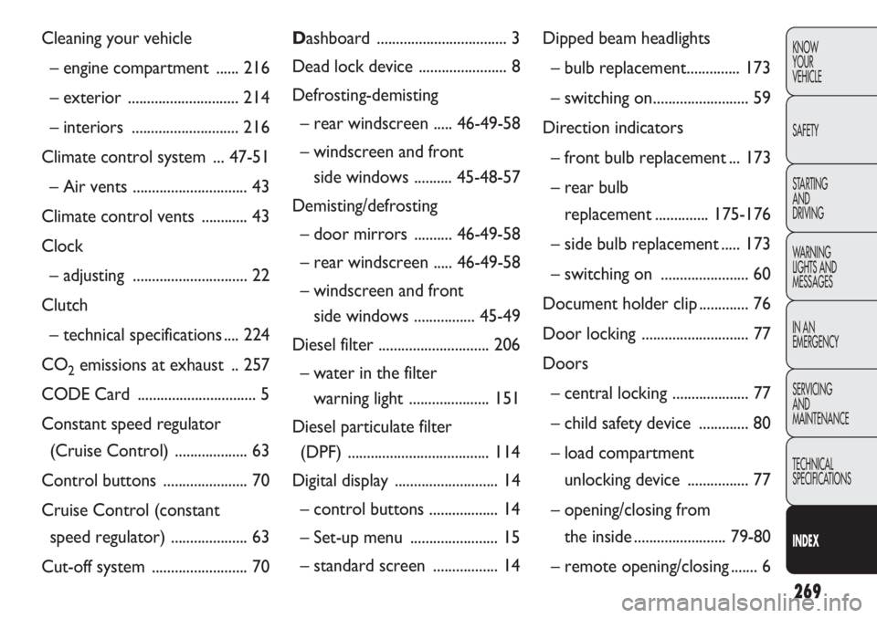
INDEXDashboard .................................. 3
Dead lock device ....................... 8
Defrosting-demisting – rear windscreen ..... 46-49-58
– windscreen and front side windows .......... 45-48-57
Demisting/defrosting – door mirro rs ..........46-49-58
– rear windscreen ..... 46-49-58
– windscreen and front side windows ................ 45-49
Diesel filter ............................. 206
– water in the filter warning light ..................... 151
Diesel particulate filter (DPF) ..................................... 114
Digital di splay ........................... 14
– control buttons .................. 14
– Set-up menu ....................... 15
– standard screen ................. 14Dipped beam headlights
– bulb replace ment.............. 173
– switching on......................... 59
Direction indicators – front bulb replacement ... 173
– rear bulb replacement ..............175-176
– side bulb replacement ..... 173
– switching on ....................... 60
Document holder clip ............. 76
Door lock ing ............................ 77
Doors – central locking .................... 77
– child safety device ............. 80
– load compartment unlocking device ................ 77
– opening/closing from the inside ........................ 79-80
– remote opening/closing ....... 6
Cleaning your vehicle
– engine compartment ...... 216
– exterior ............................. 214
– interio rs ............................ 216
Climate control system ... 47-51 – Air vents .............................. 43
Climate control vents ............ 43
Clock – adjusting .............................. 22
Clutch – technical specifications .... 224
CO
2emissions at exhaust .. 257
CODE Card ............................... 5
Constant speed regulator (Cruise Control) ................... 63
Control buttons ...................... 70
Cruise Control (constant speed regulator) .................... 63
Cut-off system ......................... 70
Page 278 of 283
274
KNOWYOUR
VEHICLE
SAFETY
STARTING AND
DRIVING
WARNING
LIGHTS AND MESSAGES
IN AN
EMERGENCY
SERVICING AND
MAINTENANCE
TECHNICAL
SPECIFICATIONS
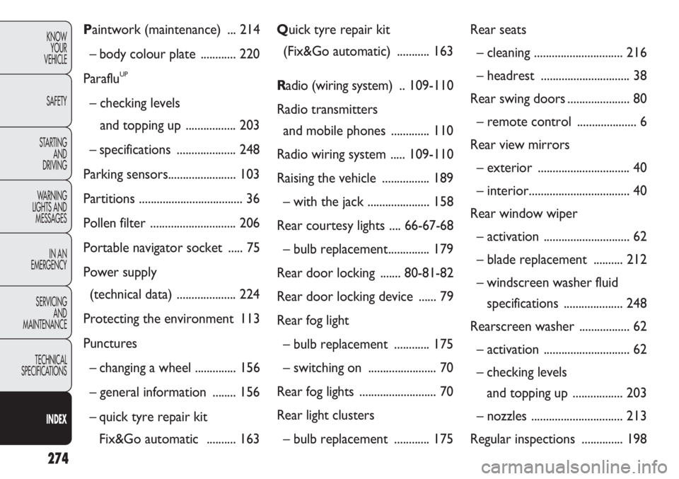
INDEXPaintwork (maintenance) ... 214
– body colour plate ............ 220
Paraflu
UP
– checking levels and topping up ................. 203
– specifications .................... 248
Parking sensors....................... 103
Partitions ................................... 36
Pollen filter ............................. 206
Portable navigator socket ..... 75
Power supply (technical data) .................... 224
Protecting the environment 113
Punctures – changing a wheel .............. 156
– general information ........ 156
– quick tyre repair kit Fix&Go automatic .......... 163 Q
uick tyre repair kit
(Fix&Go automatic) ........... 163
R adio (wiring system) .. 109-110
Radio transmitters and mobile phones ............. 110
Radio wiring system ..... 109-110
Raising the vehicle ................ 189
– with the jack ..................... 158
Rear courtesy lights .... 66-67-68 – bulb replace ment.............. 179
Rear door locking ....... 80-81-82
Rear door locking device ...... 79
Rear fog light – bulb replace ment ............ 175
– switching on ....................... 70
Rear fog lig hts .......................... 70
Rear light clusters – bulb replace ment ............ 175 Rear seats
– cleaning .............................. 216
– headrest .............................. 38
Rear swing doors ..................... 80
– remote control .................... 6
Rear view mirrors – exterior ............................... 40
– interio r.................................. 40
Rear window wiper – activation ............................. 62
– blade replacement .......... 212
– windscreen washer fluid specifications .................... 248
Rearscreen washer ................. 62
– activation ............................. 62
– checking levels and topping up ................. 203
– nozzles ............................... 213
Regular inspections .............. 198