key FIAT DOBLO COMBI 2012 Owner handbook (in English)
[x] Cancel search | Manufacturer: FIAT, Model Year: 2012, Model line: DOBLO COMBI, Model: FIAT DOBLO COMBI 2012Pages: 283, PDF Size: 6.31 MB
Page 88 of 283
84
KNOWYOUR
VEHICLE
SAFETY
ST AR
TING AND
DRIVING
WARNING
LIGHTS AND MESSAGES
IN AN
EMERGENCY
SERVICING AND
MAINTENANCE
TECHNICAL
SPECIFICATIONS
INDEX
Incorrect use of the electric window open-
ing mechanism may be dangerous. Before
and during operation, always check that no-one
is exposed to the risk of being injured directly by
the moving window or by objects getting caught
and dragged.
WARNING
When leaving the vehicle, always remove
the ignition key to avoid the risk of injury
due to accidental operation of the electric win-
dow opening mechanism.
WARNING
F0V0175mfig. 83
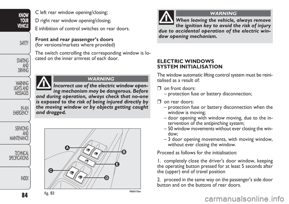
C left rear window opening/closing;
D right rear window opening/closing;
E inhibition of control switches on rear doors.
Front and rear passenger’s doors
(for versions/markets where provided)
The switch controlling the corresponding window is lo-
cated on the inner armrest of each door. ELECTRIC WINDOWS
SYSTEM INITIALISATION
The window automatic lifting control system must be reini-
tialised as a result of:
❒on front doors:
– protection fuse or battery disconnection;
❒on rear doors:– protection fuse or battery disconnection when the window is moving;
– door opening with window moving, due to the in- tervention of the antipinching system;
– 50 window movements without ever closing the win- dow;
– 3 door opening movements, with moving window, without ever closing the window.
Proceed as follows for the initialisation:
1. completely close the driver's door window, keeping
the operating button pressed for at least 5 seconds after
the (upper) end of travel position
2. proceed in the same way on the passenger's side door
button and on the buttons of rear doors.
Page 89 of 283
85
KNOW
YOUR
VEHICLE
SAFETY
STAR
TING
AND
DRIVING
WARNING
LIGHTS AND
MESSAGES
IN AN
EMERGENCY
SERVICING
AND
MAINTENANCE
TECHNICAL
SPECIFICATIONS
INDEX
F0V0370mfig. 84a
BOOT
OPENING/CLOSING THE BOOT FROM
THE OUTSIDE
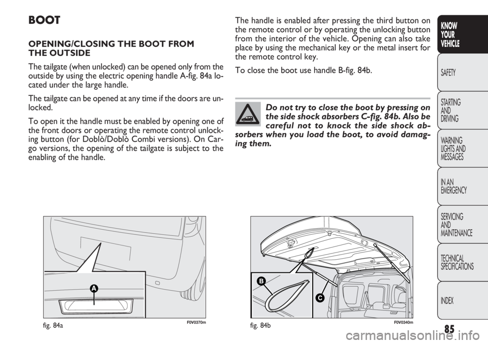
The tailgate (when unlocked) can be opened only from the
outside by using the electric opening handle A-fig. 84a lo-
cated under the large handle.
The tailgate can be opened at any time if the doors are un-
locked.
To open it the handle must be enabled by opening one of
the front doors or operating the remote control unlock-
ing button (for Doblò/Doblò Combi versions). On Car-
go versions, the opening of the tailgate is subject to the
enabling of the handle. The handle is enabled after pressing the third button on
the remote control or by operating the unlocking button
from the interior of the vehicle. Opening can also take
place by using the mechanical key or the metal insert for
the remote control key.
To close the boot use handle B-fig. 84b.
Do not try to close the boot by pressing on
the side shock absorbers C-fig. 84b. Also be
careful not to knock the side shock ab-
sorbers when you load the boot, to avoid damag-
ing them.
F0V0340mfig. 84b
Page 96 of 283
F0V0048mfig. 9492
KNOWYOUR
VEHICLE
SAFETY
ST AR
TING AND
DRIVING
WARNING
LIGHTS AND MESSAGES
IN AN
EMERGENCY
SERVICING AND
MAINTENANCE
TECHNICAL
SPECIFICATIONS
INDEX
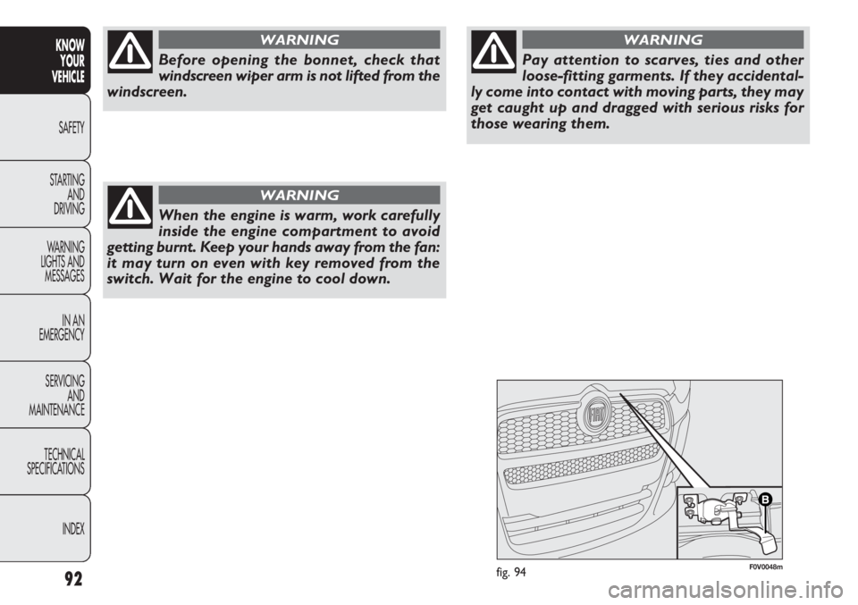
Before opening the bonnet, check that
windscreen wiper arm is not lifted from the
windscreen.
WARNING
When the engine is warm, work carefully
inside the engine compartment to avoid
getting burnt. Keep your hands away from the fan:
it may turn on even with key removed from the
switch. Wait for the engine to cool down.
WARNING
Pay attention to scarves, ties and other
loose-fitting garments. If they accidental-
ly come into contact with moving parts, they may
get caught up and dragged with serious risks for
those wearing them.
WARNING
Page 99 of 283
95
KNOW
YOUR
VEHICLE
SAFETY
STAR
TING
AND
DRIVING
WARNING
LIGHTS AND
MESSAGES
IN AN
EMERGENCY
SERVICING
AND
MAINTENANCE
TECHNICAL
SPECIFICATIONS
INDEX
F0V0021mfig. 100
H EA DLIG HTS
LIGHT BEAM DIRECTION
The correct direction of the headlights is essential for the
comfort and safety of the driver and other road users.
To ensure the best visibility conditions when travelling with
the headlights on the headlight alignment must be correct.
Contact the Fiat Service Network to have the direction
checked and, if necessary, adjusted.
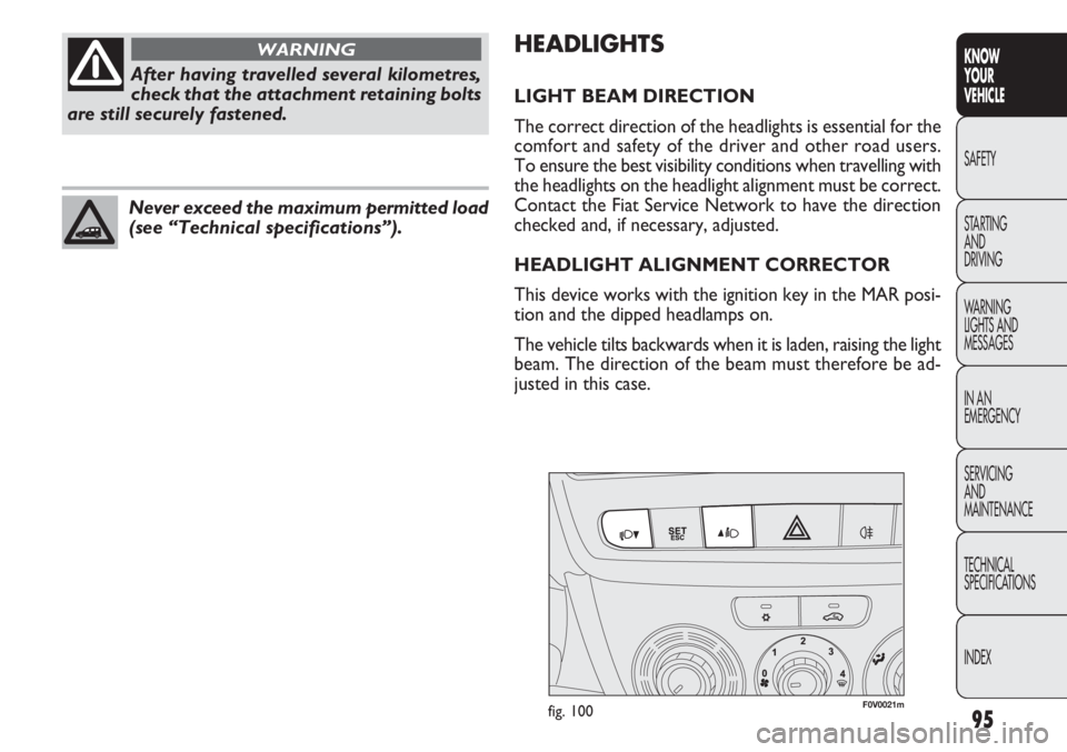
HEADLIGHT ALIGNMENT CORRECTOR
This device works with the ignition key in the MAR posi-
tion and the dipped headlamps on.
The vehicle tilts backwards when it is laden, raising the light
beam. The direction of the beam must therefore be ad-
justed in this case.
After having travelled several kilometres,
check that the attachment retaining bolts
are still securely fastened.
WARNING
Never exceed the maximum permitted load
(see “Technical specifications”).
Page 106 of 283
102
KNOWYOUR
VEHICLE
SAFETY
ST AR
TING AND
DRIVING
WARNING
LIGHTS AND MESSAGES
IN AN
EMERGENCY
SERVICING AND
MAINTENANCE
TECHNICAL
SPECIFICATIONS
INDEX
EOBD SY STE M
The EOBD system (European On Board Diagnosis) allows
continuous diagnosis of emission-related components on
the vehicle. It also alerts the driver, by turning on warn-
ing light U in the instrument panel (together with the rel-
evant message in the display on some versions), when
these components are no longer in peak condition (see
“Warning lights and messages” section).
The goal of the system is to:
❒keep the system efficiency under control;
❒warn about increased emissions due to a vehicle mal-
function;
❒warn of the need to replace deteriorated components.
The system also has a diagnostic connector that can be in-
terfaced with appropriate equipment, which makes it pos-
sible to read the error codes memorized in the control
unit together with a series of specific parameters for en-
gine operation and diagnosis.
This check can also be carried out by traffic authorities.
WARNING After eliminating the problem, to check the
system completely, Fiat Service Network run a bench test
and, if necessary, road tests which may also call for a long
journey.
Go to the Fiat Service Network as soon
as possible if warning light
Udoes not
light up when the ignition key is turned to MAR
or if, while travelling, the warning light comes on
either permanently or flashing (along with a mes-
sage on the display on certain versions). The op-
eration of the
Uwarning light may be checked
by the traffic authorities using specific devices. Re-
spect the regulations in force in the country where
you are driving.
WARNING
SPEED BLOCK
(for versions/markets where provided)
The vehicle is equipped with a speed limitation function
that can be set at the user’s request to one of four pre-
defined values: 90, 100, 110, 130 km/h.
To activate/deactivate this function, contact the Fiat Ser-
vice Network.
Following the operation, a sticker will be applied to the
windscreen showing the top speed setting.
WARNING The speedometer could show a higher top
speed than the one set by the Dealership in accordance
with the regulations in force.
Page 110 of 283
❒vehicle in motion, for example when driving on hilly
roads;
❒stopping the engine through the Start&Stop system for
more than about three minutes.
❒automatic climate control system for establishing a
comfortable temperature or enabling the MAX – DEF
function.
With a gear engaged, the engine can only be automatical-
ly restarted by fully depressing the clutch pedal. The dri-
ver is asked to perform this operation through the warn-
ing light flashing in the instrument panel fig. 103 and, where
provided, the message in the display.
N.B.: If the clutch is not depressed when the three min-
utes have elapsed since the engine was stopped, the en-
gine can only be restarted using the key.
N.B.: If you stall the engine, for example by releasing off
the clutch pedal quickly with gear engaged, if the
Start&Stop system is activated, the engine can be restart-
ed by fully depressing the clutch pedal or by putting the
gear lever into neutral.
SAFETY FUNCTIONS
In engine cut-out conditions through the Start&Stop sys-
tem, if the driver unfastens his/her seat belt and opens the
driver’s side door or the passenger’s side door, the engine
can only be restarted using the key.
The driver is notified of this condition by a buzzer, through
the warning light flashing in the instrument panel fig. 103
and, where provided, by a message in the display.
106
KNOW YOUR
VEHICLE
SAFETY
ST AR
TING AND
DRIVING
WARNING
LIGHTS AND MESSAGES
IN AN
EMERGENCY
SERVICING AND
MAINTENANCE
TECHNICAL
SPECIFICATIONS
INDEX
❒heated rear windscreen on;
❒windscreen wipers working at maximum speed;
❒particulate filter regeneration in progress (diesel en-
gines only);
❒driver’s door not shut;
❒driver’s seat belt not fastened;
❒reverse gear engaged (for example, during parking ma-
noeuvres);
❒automatic climate control is on and a comfortable tem-
perature has not yet been reached or MAX – DEF func-
tion enabled.
❒during the first period of use, to initialise the system
In the above cases, the warning light flashes fig. 103 and,
where available, there is a message in the display.
RESTARTING CONDITIONS
For reasons of comfort, limiting pollutant emissions and
safety purposes, the power unit can restart automatically
without any action on behalf of the driver if certain con-
ditions are met, including:
❒battery not sufficiently charged;
❒windscreen wipers working at maximum speed;
❒reduced braking system vacuum, e.g. following the
brake pedal being pressed repeatedly;
Page 111 of 283
107
KNOW
YOUR
VEHICLE
SAFETY
STAR
TING
AND
DRIVING
WARNING
LIGHTS AND
MESSAGES
IN AN
EMERGENCY
SERVICING
AND
MAINTENANCE
TECHNICAL
SPECIFICATIONS
INDEX
F0V0041mfig. 105
ENERGY SAVING FUNCTION
(for versions/markets where provided)
If, after the engine has been automatically restarted, the
driver does not take any action for a period of about 3 min-
utes, the Start&Stop system will definitively stop the en-
gine to avoid fuel consumption. The engine can only be
started using the key in such cases.
N.B.: In any case, it is possible to keep the engine running
by deactivating the Start&Stop system.
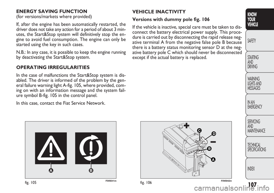
OPERATING IRREGULARITIES
In the case of malfunctions the Start&Stop system is dis-
abled. The driver is informed of the problem by the gen-
eral failure warning light A-fig. 105, where provided, com-
ing on with an information message and the system fail-
ure symbol B-fig. 105 in the control panel.
In this case, contact the Fiat Service Network. VEHICLE INACTIVITY
Versions with dummy pole fig. 106
If the vehicle is inactive, special care must be taken to dis-
connect the battery electrical power supply. This proce-
dure is carried out by disconnecting the rapid release neg-
ative terminal A from the negative false pole B because
there is a battery status monitoring sensor D at the neg-
ative battery pole C which should never be disconnected
except if the actual battery is replaced.
F0V0042mfig. 106
Page 112 of 283
108
KNOWYOUR
VEHICLE
SAFETY
ST AR
TING AND
DRIVING
WARNING
LIGHTS AND MESSAGES
IN AN
EMERGENCY
SERVICING AND
MAINTENANCE
TECHNICAL
SPECIFICATIONS
INDEX
F0V0043mfig. 107
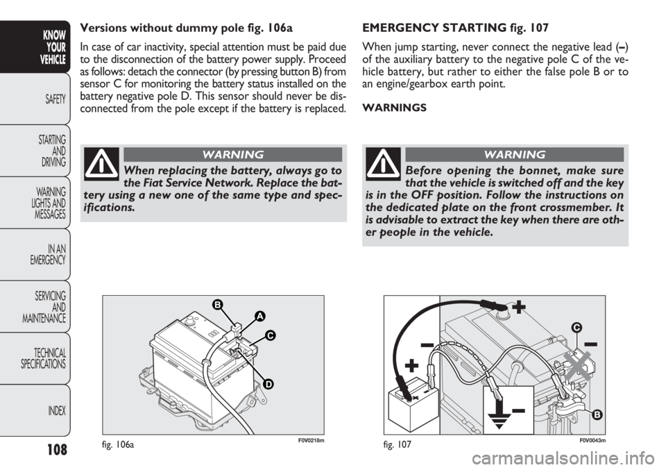
EMERGENCY STARTING fig. 107
When jump starting, never connect the negative lead ( –)
of the auxiliary battery to the negative pole C of the ve-
hicle battery, but rather to either the false pole B or to
an engine/gearbox earth point.
WARNINGS
When replacing the battery, always go to
the Fiat Service Network. Replace the bat-
tery using a new one of the same type and spec-
ifications.
WARNING
Before opening the bonnet, make sure
that the vehicle is switched off and the key
is in the OFF position. Follow the instructions on
the dedicated plate on the front crossmember. It
is advisable to extract the key when there are oth-
er people in the vehicle.
WARNING
F0V0218mfig. 106a
Versions without dummy pole fig. 106a
In case of car inactivity, special attention must be paid due
to the disconnection of the battery power supply. Proceed
as follows: detach the connector (by pressing button B) from
sensor C for monitoring the battery status installed on the
battery negative pole D. This sensor should never be dis-
connected from the pole except if the battery is replaced.
Page 113 of 283
109
KNOW
YOUR
VEHICLE
SAFETY
STAR
TING
AND
DRIVING
WARNING
LIGHTS AND
MESSAGES
IN AN
EMERGENCY
SERVICING
AND
MAINTENANCE
TECHNICAL
SPECIFICATIONS
INDEX
RADIO
(for versions/markets where provided)
For the operation of the radio with CD/MP3 player (for
versions/markets where provided), read the Supplement
attached to this Owner’s Handbook.
WIRING FOR LIGHTWEIGHT SYSTEM
The system consists of:
❒radio power cables;
❒front speaker cables (located on door mirror trims);
❒speaker cables on front door panels;
❒rear speaker cables (located next to the parcel shelf)
(for versions/markets where provided);
❒radio compartment;
❒aerial lead;
❒aerial.
WIRING FOR HEAVYWEIGHT SYSTEM
The system consists of:
❒radio power cables;
❒rear speaker cables (located next to the parcel shelf)
(for versions/markets where provided);
❒two tweeters on the door mirror trims;
❒two midwoofers on the lower part of the front doors;
The vehicle should always be evacuated
after the key has been removed or turned
to the OFF position. During refuelling operations,
it is necessary to make sure that the vehicle is off
with the ignition key in the OFF position.
WARNING
For vehicles with a robotised transmission,
if the engine cuts out automatically on
a gradient, it is advisable to restart the engine by
moving the gear lever towards (+) or (-) without
releasing the brake pedal. For vehicles with ro-
botised transmission, where the Hill Holder func-
tion is present, if the engine cuts out automati-
cally whilst on a hill, it is advisable to restart it
by moving the gear lever to (+) or (-) without re-
leasing the brake pedal to make the Hill Holder
function – which is only active when the engine
is running – available.
WARNING
If you want to prioritise climate comfort,
the Start&Stop system can be disabled to
allow continuous operation of the climate control
system.
WARNING
Page 116 of 283
112
KNOWYOUR
VEHICLE
SAFETY
ST AR
TING AND
DRIVING
WARNING
LIGHTS AND MESSAGES
IN AN
EMERGENCY
SERVICING AND
MAINTENANCE
TECHNICAL
SPECIFICATIONS
INDEX
F0V0086mfig. 109
REFUELLING CAPACITY
To fill the tank completely, top up twice after the pump
switches off. Further top ups could cause faults in the fu-
el supply system. If using/parking the vehicle in mountainous/cold areas for
a long time, you should refuel with locally available diesel.
In this case, it is also advisable to keep the tank over 50% full.
For diesel engines, use only diesel fuel for
motor vehicles in accordance with EN590
European specifications. The use of other
products or mixtures may damage the engine be-
yond repair and consequently invalidate the war-
ranty, depending on the damage caused. If you ac-
cidentally introduce other types of fuel into the
tank, do not start the engine. Empty the tank. If the
engine has run, even for a very short time, you will
need to have the entire fuel supply system emptied
in addition to the tank.
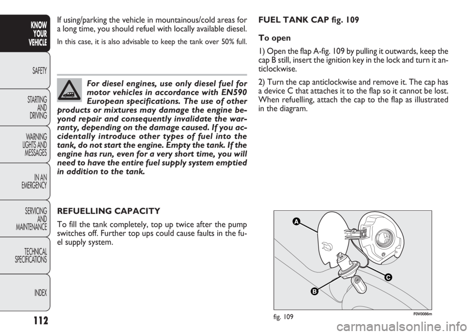
FUEL TANK CAP fig. 109
To open
1) Open the flap A-fig. 109 by pulling it outwards, keep the
cap B still, insert the ignition key in the lock and turn it an-
ticlockwise.
2) Turn the cap anticlockwise and remove it. The cap has
a device C that attaches it to the flap so it cannot be lost.
When refuelling, attach the cap to the flap as illustrated
in the diagram.