stop start FIAT DOBLO COMBI 2012 Owner handbook (in English)
[x] Cancel search | Manufacturer: FIAT, Model Year: 2012, Model line: DOBLO COMBI, Model: FIAT DOBLO COMBI 2012Pages: 283, PDF Size: 6.31 MB
Page 8 of 283
4
KNOWYOUR
VEHICLE
SAFETY
ST AR
TINGAND
DRIVING
WARNING
LIGHTS AND MESSAGES
IN AN
EMERGENCY
SERVICING AND
MAINTENANCE
TECHNICAL
SPECIFICATIONS
INDEX
THE FIAT CODE SYSTEM
This is an electrical engine immobiliser system which in-
creases protection against attempted theft of the vehicle.
It is automatically activated when the ignition key is ex-
tracted.
Each key contains an electronic device which modulates
the signal emitted during starting by an antenna built into
the starting device. This signal is the ‘password’ which
changes at each starting and which the control unit uses
to recognise the key and enable starting.
OPERATION
Each time the vehicle is started by turning the ignition key
to MAR, the Fiat CODE system control unit sends a recog-
nition code to the engine management control unit to de-
activate the immobiliser.
The code is only sent if the Fiat CODE system control unit
has recognised the code transmitted by the key.
Each time the ignition key is turned to STOP, the Fiat
CODE system deactivates the functions of the engine man-
agement control unit.
If, during starting, the code is not correctly recognised,
warning light
Ylights up in the instrument panel.
In this case, turn the key to STOP and then to MAR; if it
is still locked, try again with the other keys that come with
the vehicle. Contact a Fiat Service Network if you still can-
not start the engine.
SYMBOLS
Special coloured labels have been attached near or on
some of the components of your vehicle. These labels bear
symbols that draw your attention to the precautions re-
quired when handling the component in question.
A plate summarising these symbols can be found under the
engine bonnet.
Page 13 of 283
9
KNOW
YOUR
VEHICLE
SAFETY
STAR
TING
AND
DRIVING
WARNING
LIGHTS AND
MESSAGES
IN AN
EMERGENCY
SERVICING
AND
MAINTENANCE
TECHNICAL
SPECIFICATIONS
INDEX
STARTING DEVICE
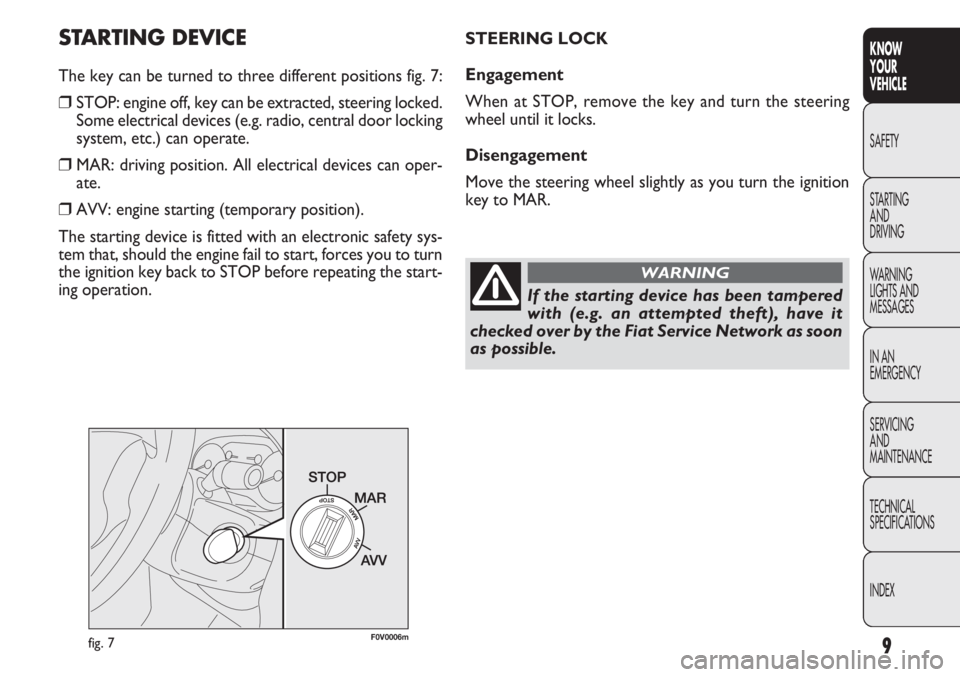
The key can be turned to three different positions fig. 7:
❒STOP: engine off, key can be extracted, steering locked.
Some electrical devices (e.g. radio, central door locking
system, etc.) can operate.
❒MAR: driving position. All electrical devices can oper-
ate.
❒AVV: engine starting (temporary position).
The starting device is fitted with an electronic safety sys-
tem that, should the engine fail to start, forces you to turn
the ignition key back to STOP before repeating the start-
ing operation.
F0V0006mfig. 7
STEERING LOCK
Engagement
When at STOP, remove the key and turn the steering
wheel until it locks.
Disengagement
Move the steering wheel slightly as you turn the ignition
key to MAR.
If the starting device has been tampered
with (e.g. an attempted theft), have it
checked over by the Fiat Service Network as soon
as possible.
WARNING
Page 17 of 283
13
KNOW
YOUR
VEHICLE
SAFETY
STAR
TING
AND
DRIVING
WARNING
LIGHTS AND
MESSAGES
IN AN
EMERGENCY
SERVICING
AND
MAINTENANCE
TECHNICAL
SPECIFICATIONS
INDEX
F0V0009mfig. 13
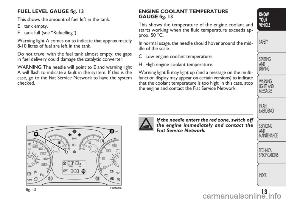
ENGINE COOLANT TEMPERATURE
GAUGE fig. 13
This shows the temperature of the engine coolant and
starts working when the fluid temperature exceeds ap-
prox. 50 °C.
In normal usage, the needle should hover around the mid-
dleofthescale.
C Low engine coolant temperature.
H High engine coolant temperature.
Warning light B may light up (and a message on the multi-
function display may appear on certain versions) to indicate
that the coolant temperature is too high; in this case, stop
the engine and contact the Fiat Service Network.
FUEL LEVEL GAUGE fig. 13
This shows the amount of fuel left in the tank.
E tank empty.
F tank full (see “Refuelling”).
Warning light A comes on to indicate that approximately
8-10 litres of fuel are left in the tank.
Do not travel with the fuel tank almost empty: the gaps
in fuel delivery could damage the catalytic converter.
WARNING The needle will point to E and warning light
A will flash to indicate a fault in the system. If this is the
case, go to the Fiat Service Network to have the system
checked.
If the needle enters the red zone, switch off
the engine immediately and contact the
Fiat Service Network.
Page 18 of 283
14
KNOWYOUR
VEHICLE
SAFETY
ST AR
TINGAND
DRIVING
WARNING
LIGHTS AND MESSAGES
IN AN
EMERGENCY
SERVICING AND
MAINTENANCE
TECHNICAL
SPECIFICATIONS
INDEX
DIGITAL DISPLAY
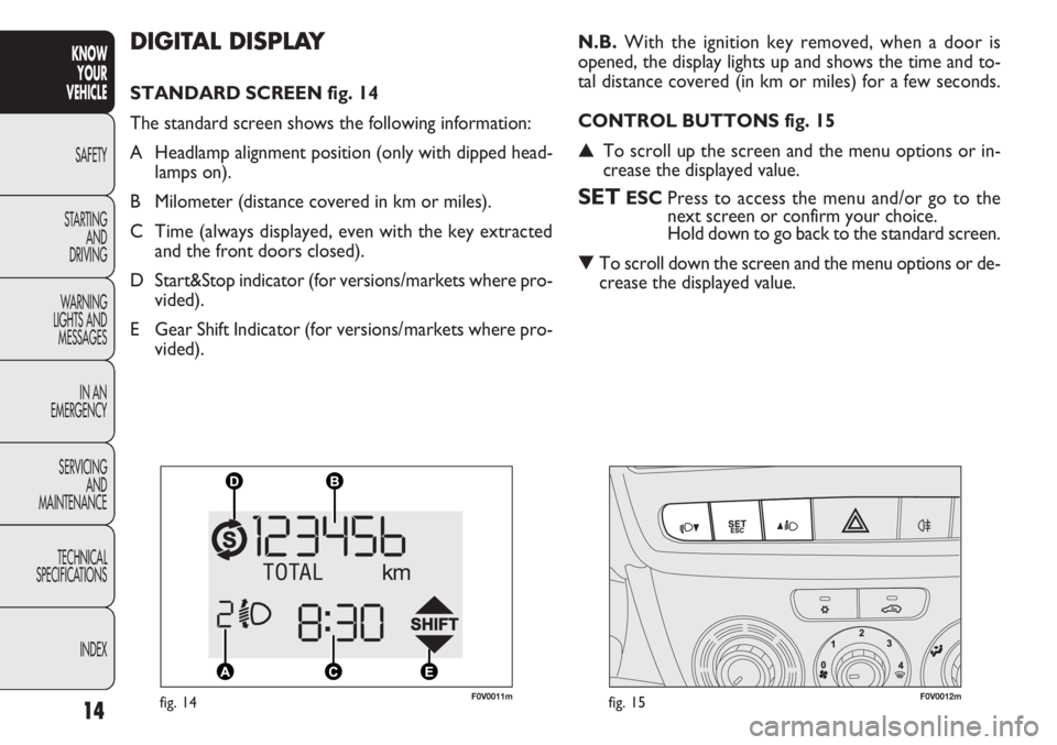
STANDARD SCREEN fig. 14
The standard screen shows the following information:
A Headlamp alignment position (only with dipped head-lamps on).
B Milometer (distance covered in km or miles).
C Time (always displayed, even with the key extracted and the front doors closed).
D Start&Stop indicator (for versions/markets where pro- vided).
E Gear Shift Indicator (for versions/markets where pro- vided). N.B.
With the ignition key removed, when a door is
opened, the display lights up and shows the time and to-
tal distance covered (in km or miles) for a few seconds.
CONTROL BUTTONS fig. 15
▲ To scroll up the screen and the menu options or in-
crease the displayed value.
SETESC Press to access the menu and/or go to the
next screen or confirm your choice.
Hold down to go back to the standard screen.
▼ To scroll down the screen and the menu options or de-
crease the displayed value.
F0V0011mfig. 14F0V0012mfig. 15
Page 23 of 283
19
KNOW
YOUR
VEHICLE
SAFETY
STAR
TING
AND
DRIVING
WARNING
LIGHTS AND
MESSAGES
IN AN
EMERGENCY
SERVICING
AND
MAINTENANCE
TECHNICAL
SPECIFICATIONS
INDEX
F0V0038mfig. 16F0V0012mfig. 17
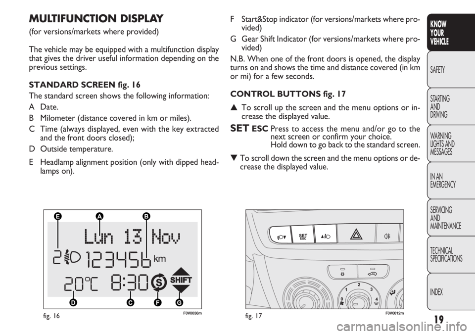
F Start&Stop indicator (for versions/markets where pro-
vided)
G Gear Shift Indicator (for versions/markets where pro- vided)
N.B. When one of the front doors is opened, the display
turns on and shows the time and distance covered (in km
or mi) for a few seconds.
CONTROL BUTTONS fig. 17
▲ To scroll up the screen and the menu options or in-
crease the displayed value.
SETESC Press to access the menu and/or go to the
next screen or confirm your choice.
Hold down to go back to the standard screen.
▼ To scroll down the screen and the menu options or de-
crease the displayed value.
MULTIFUNCTION DISPLAY
(for versions/markets where provided)
The vehicle may be equipped with a multifunction display
that gives the driver useful information depending on the
previous settings.
STANDARD SCREEN fig. 16
The standard screen shows the following information:
A Date.
B Milometer (distance covered in km or miles).
C Time (always displayed, even with the key extracted
and the front doors closed);
D Outside temperature.
E Headlamp alignment position (only with dipped head- lamps on).
Page 61 of 283
57
KNOW
YOUR
VEHICLE
SAFETY
STAR
TING
AND
DRIVING
WARNING
LIGHTS AND
MESSAGES
IN AN
EMERGENCY
SERVICING
AND
MAINTENANCE
TECHNICAL
SPECIFICATIONS
INDEX
❒the maximum air temperature for the HI air is set in
both areas;
❒sets the fan speed set according to the engine coolant
temperature to limit the flow of air that is insufficiently
warm to demist the windows;
❒the air flow is directed to the windscreen and front
door window glasses diffusers;
❒switches on the heated rear windscreen
WARNING The rapid demisting/defrosting function for
the windows remains on for about 3 minutes from when
the engine coolant reaches the appropriate temperature
for a rapid demisting of the windows.
When this function is active, the LED in the correspond-
ing button and the one for the heated rear windscreen but-
ton switch on. The message FULL AUTO goes off on the
display.
You can only adjust the fan speed and switch the heated
rear windscreen off manually when this function is active.
To restore the previous operating conditions, simply press
button B, air recirculation button G, compressor button
F or AUTO button A.
IMPORTANT With the compressor off, it is not possible
to introduce air into the passenger compartment at a tem-
perature lower than that of the outside air. In certain
weather conditions, the windows could mist up rapidly due
to the non-dehumidified air.
The switching off of the compressor remains memorised
even when the engine has been stopped.
To restore automatic compressor engagement control,
press the √
button again (in this case, the system will work
only as a heater) or press the AUTO button.
With the compressor switched off, if the outside tem-
perature is higher than the one set, the system is not ca-
pable of satisfying this request and signals it by the digits
for the temperature setting flashing after which the word
AUTO goes out.
With the climate control compressor off, the fan speed
can be set to zero manually (no bar shown).
With the compressor enabled and the engine started, the
fan speed may only be reduced to the minimum setting
(one bar shown).
Button for rapid window demisting/defrosting (D)
Press this button and the climate control system will au-
tomatically switch on all the functions required for fast
windscreen and side window demisting/defrosting:
❒the climate control compressor is turned on when
weather conditions are suitable;
❒the air recirculation is turned off;
Page 62 of 283
58
KNOWYOUR
VEHICLE
SAFETY
ST AR
TING AND
DRIVING
WARNING
LIGHTS AND MESSAGES
IN AN
EMERGENCY
SERVICING AND
MAINTENANCE
TECHNICAL
SPECIFICATIONS
INDEX
Switching the system OFF (E)
Press button E to switch the climate control system off.
The display goes off.
With the system off, the following climate control sys-
tem conditions are in place: display off, set temperature
not displayed, air recirculation on to insulate the passen-
ger compartment (recirculation LED on), climate control
compressor off, fan off. Press the AUTO button to switch
the climate control system back on in fully automatic mode.
Heated rear windscreen and electric door
mirrors
demisting/defrosting button(L)
(for versions/markets where provided)
Push this button to activate the demisting/defrosting of the
heated rear windscreen
and electrically controlled door
mirrors
When this function is active, the button LED is on.
This function switches off automatically after about 20 min-
utes or when you push the button again, or when the en-
gine is turned off. It will not be switched on automatical-
ly when the engine is restarted.
WARNING Do not apply stickers over the electric fila-
ments on the inside of the heated rear window to prevent
damage that might stop it working properly.
Page 84 of 283
80
KNOW
YOUR
VEHICLE
SAFETY
STARTING
AND
DRIVING
WARNING
LIGHTS AND
MESSAGES
IN AN
EMERGENCY
SERVICING
AND
MAINTENANCE
TECHNICAL
SPECIFICATIONS
INDEX
F0V0186mfig. 76
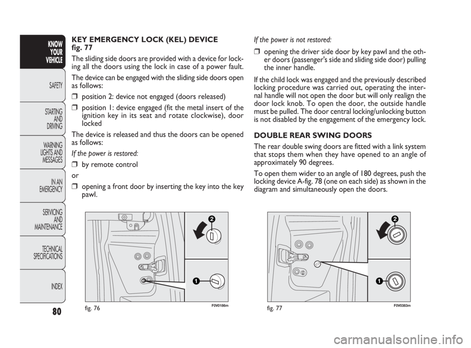
KEY EMERGENCY LOCK (KEL) DEVICE
fig. 77
The sliding side doors are provided with a device for lock-
ing all the doors using the lock in case of a power fault.
The device can be engaged with the sliding side doors open
as follows:
❒position 2: device not engaged (doors released)
❒position 1: device engaged (fit the metal insert of the
ignition key in its seat and rotate clockwise), door
locked
The device is released and thus the doors can be opened
as follows:
If the power is restored:
❒by remote control
or
❒opening a front door by inserting the key into the key
pawl.
F0V0383mfig. 77
If the power is not restored:
❒opening the driver side door by key pawl and the oth-
er doors (passenger's side and sliding side door) pulling
the inner handle.
If the child lock was engaged and the previously described
locking procedure was carried out, operating the inter-
nal handle will not open the door but will only realign the
door lock knob. To open the door, the outside handle
must be pulled. The door central locking/unlocking button
is not disabled by the engagement of the emergency lock.
DOUBLE REAR SWING DOORS
The rear double swing doors are fitted with a link system
that stops them when they have opened to an angle of
approximately 90 degrees.
To open them wider to an angle of 180 degrees, push the
locking device A-fig. 78 (one on each side) as shown in the
diagram and simultaneously open the doors.
035-114 DOBLO LUM EN 1ed 6-02-2012 9:39 Pagina 80
Page 102 of 283
98
KNOWYOUR
VEHICLE
SAFETY
ST AR
TING AND
DRIVING
WARNING
LIGHTS AND MESSAGES
IN AN
EMERGENCY
SERVICING AND
MAINTENANCE
TECHNICAL
SPECIFICATIONS
INDEX
ESP SYSTEM
(Electronic Stability Program)
(for versions/markets where provided)
This is an electronic system that controls vehicle stability
in the event of tyre grip loss, helping to maintain direc-
tional control.
The ESP system is therefore particularly useful when grip
conditions of road surfaces change.
The MSR system (adjustment of the engine braking torque
during gear downshifts) and the HBA system (automatic
increase in the braking pressure during emergency brak-
ing) are present with ESP, ASR and Hill Holder systems
(for versions/markets where provided).
SYSTEM INTERVENTION
This is signalled by the flashing of warning light
áin the in-
strument panel, to inform the driver that the vehicle is in
critical stability and grip conditions.
SYSTEM ACTIVATION
The ESP system is automatically activated when the vehi-
cle is started and cannot be de-activated.
BRAKE ASSIST (emergency braking assistance
integrated in ESP)
(for versions/markets where provided)
This system (which cannot be deactivated) recognises
emergency braking conditions according to the speed of
operation of the brake pedal and provides an additional
hydraulic braking pressure to support that provided by the
driver. This allows faster and more powerful operation
of the braking system.
Brake Assist is deactivated on the versions equipped with
ESP, in the event of ESP system failure (indicated by warn-
ing light
ácoming on together with the message in the
multifunction display, where provided).
When the ABS cuts in, and you feel the
brake pedal pulsating, do not remove your
foot, but keep it pressed; in doing so you will stop
in the shortest distance possible under the road
conditions at the time.
WARNING
Page 108 of 283
F0V0040mfig. 103
START&STOP SYSTEM
FOREWORD
The Start&Stop device automatically stops the engine each
time the vehicle is stationary and starts it again when the
driver wants to move off.
This improves the efficiency of the vehicle by reducing fu-
el consumption, the emission of harmful gases and noise
pollution.
The system is activated each time the vehicle is started.
OPERATING MODES
Engine cut-out mode
WITH MANUAL TRANSMISSION
With the vehicle stationary, the engine cuts out with the
gearbox in neutral and the clutch pedal released.
104
KNOWYOUR
VEHICLE
SAFETY
ST AR
TING AND
DRIVING
WARNING
LIGHTS AND MESSAGES
IN AN
EMERGENCY
SERVICING AND
MAINTENANCE
TECHNICAL
SPECIFICATIONS
INDEX
GENERAL WARNINGS
❒When parking, pay special attention to obstacles that
may be set above or below the sensors.
❒Sometimes, objects located very near the rear of the
vehicle are not detected and could therefore damage
the vehicle or be damaged themselves.
❒The signals sent out by the sensors can be altered by
dirt, snow or ice deposited on the sensors or by ul-
trasound systems (e.g. truck pneumatic brakes or pneu-
matic drills) near the vehicle.
❒The parking sensors work properly with the swing
doors closed. If they are open, they can cause the sys-
tem to send false signals: always close the rear doors.
The ultimate responsibility when parking
and carrying out other dangerous ma-
noeuvres still rests with the driver. When park-
ing, make sure that no-one is standing in the area,
especially children or animals. Parking sensors are
designed to assist drivers; however, you must al-
ways concentrate fully during potentially danger-
ous manoeuvres, even if carried out at low speeds.
WARNING