lock FIAT DOBLO COMBI 2012 Owner handbook (in English)
[x] Cancel search | Manufacturer: FIAT, Model Year: 2012, Model line: DOBLO COMBI, Model: FIAT DOBLO COMBI 2012Pages: 283, PDF Size: 6.31 MB
Page 174 of 283
170
KNOWYOUR
VEHICLE
SAFETY
STARTING AND
DRIVING
WARNING
LIGHTS AND MESSAGES
IN AN
EMERGENCY
SERVICING AND
MAINTENANCE
TECHNICAL
SPECIFICA TIONS
INDEX
F0V0027mfig. 149
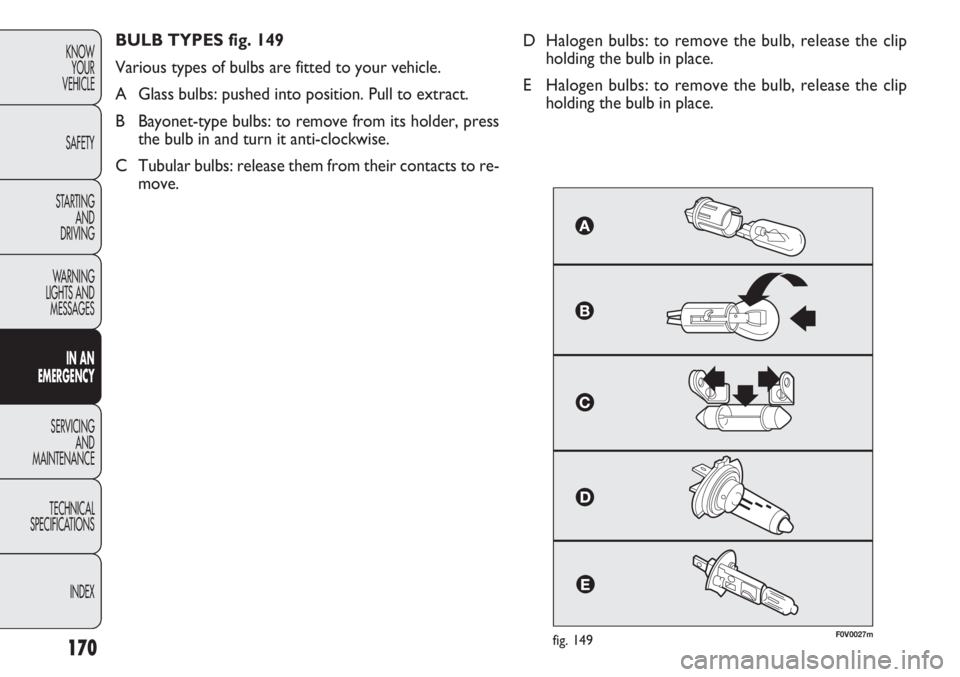
BULB TYPES fig. 149
Various types of bulbs are fitted to your vehicle.
A Glass bulbs: pushed into position. Pull to extract.
B Bayonet-type bulbs: to remove from its holder, press the bulb in and turn it anti-clockwise.
C Tubular bulbs: release them from their contacts to re- move. D Halogen bulbs: to remove the bulb, release the clip
holding the bulb in place.
E Halogen bulbs: to remove the bulb, release the clip holding the bulb in place.
Page 176 of 283
172
KNOWYOUR
VEHICLE
SAFETY
STARTING AND
DRIVING
WARNING
LIGHTS AND MESSAGES
IN AN
EMERGENCY
SERVICING AND
MAINTENANCE
TECHNICAL
SPECIFICA TIONS
INDEX
F0V0028mfig. 150F0V0029mfig. 151
CHANGING AN EXTERIOR BULB
For the type of bulb and relevant power rating, see
“Changing a bulb”.
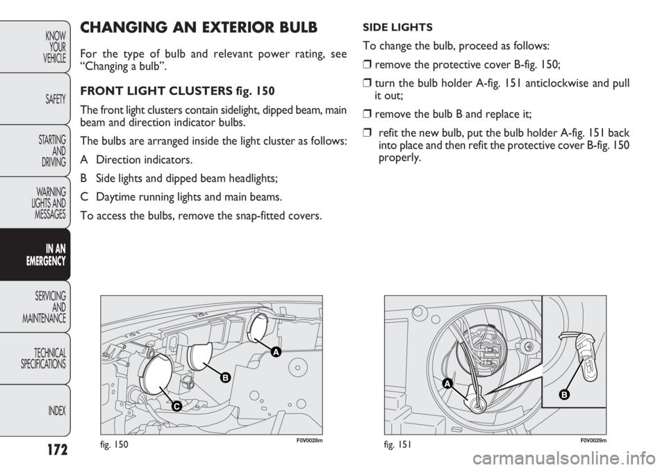
FRONT LIGHT CLUSTERS fig. 150
The front light clusters contain sidelight, dipped beam, main
beam and direction indicator bulbs.
The bulbs are arranged inside the light cluster as follows:
A Direction indicators.
B Side lights and dipped beam headlights;
C Daytime running lights and main beams.
To access the bulbs, remove the snap-fitted covers.
SIDE LIGHTS
To change the bulb, proceed as follows:
❒ remove the protective cover B-fig. 150;
❒ turn the bulb holder A-fig. 151 anticlockwise and pull
it out;
❒ remove the bulb B and replace it;
❒ refit the new bulb, put the bulb holder A-fig. 151 back
into place and then refit the protective cover B-fig. 150
properly.
Page 177 of 283
173
KNOW
YOUR
VEHICLE
SAFETY
STARTING
AND
DRIVING
WARNING
LIGHTS AND
MESSAGES
IN AN
EMERGENCY
SERVICING
AND
MAINTENANCE
TECHNICAL
SPECIFICATIONS
INDEX
F0V0030mfig. 152F0V0031mfig. 153
DIRECTION INDICATORS
Front
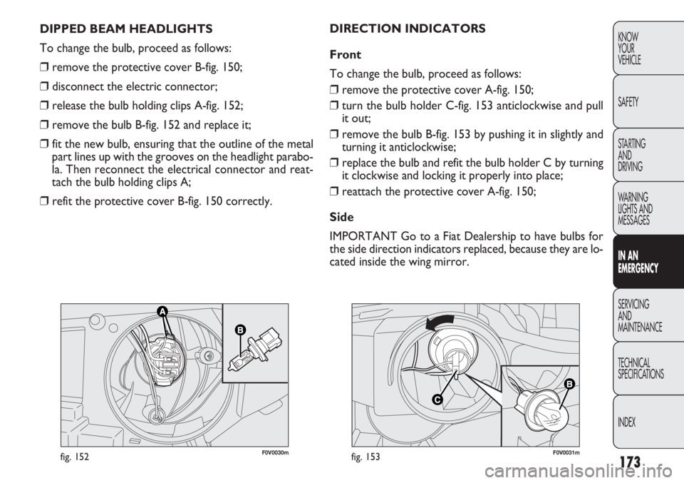
To change the bulb, proceed as follows:
❒ remove the protective cover A-fig. 150;
❒ turn the bulb holder C-fig. 153 anticlockwise and pull
it out;
❒ remove the bulb B-fig. 153 by pushing it in slightly and
turning it anticlockwise;
❒ replace the bulb and refit the bulb holder C by turning
it clockwise and locking it properly into place;
❒ reattach the protective cover A-fig. 150;
Side
IMPORTANT Go to a Fiat Dealership to have bulbs for
the side direction indicators replaced, because they are lo-
cated inside the wing mirror.
DIPPED BEAM HEADLIGHTS
To change the bulb, proceed as follows:
❒
remove the protective cover B-fig. 150;
❒ disconnect the electric connector;
❒ release the bulb holding clips A-fig. 152;
❒ remove the bulb B-fig. 152 and replace it;
❒ fit the new bulb, ensuring that the outline of the metal
part lines up with the grooves on the headlight parabo-
la. Then reconnect the electrical connector and reat-
tach the bulb holding clips A;
❒ refit the protective cover B-fig. 150 correctly.
Page 178 of 283
174
KNOWYOUR
VEHICLE
SAFETY
STARTING AND
DRIVING
WARNING
LIGHTS AND MESSAGES
IN AN
EMERGENCY
SERVICING AND
MAINTENANCE
TECHNICAL
SPECIFICA TIONS
INDEX
F0V0032mfig. 154F0V0033mfig. 155
DAYTIME RUNNING LIGHTS
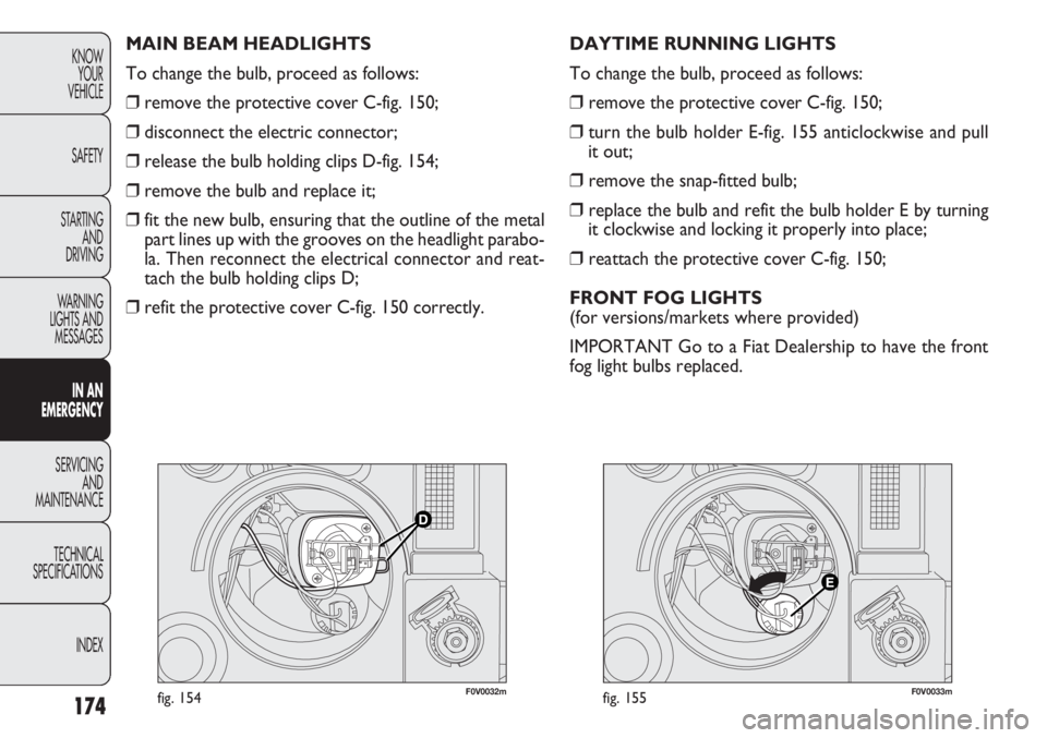
To change the bulb, proceed as follows:
❒ remove the protective cover C-fig. 150;
❒ turn the bulb holder E-fig. 155 anticlockwise and pull
it out;
❒ remove the snap-fitted bulb;
❒ replace the bulb and refit the bulb holder E by turning
it clockwise and locking it properly into place;
❒ reattach the protective cover C-fig. 150;
FRONT FOG LIGHTS
(for versions/markets where provided)
IMPORTANT Go to a Fiat Dealership to have the front
fog light bulbs replaced.
MAIN BEAM HEADLIGHTS
To change the bulb, proceed as follows:
❒
remove the protective cover C-fig. 150;
❒ disconnect the electric connector;
❒ release the bulb holding clips D-fig. 154;
❒ remove the bulb and replace it;
❒ fit the new bulb, ensuring that the outline of the metal
part lines up with the grooves on the headlight parabo-
la. Then reconnect the electrical connector and reat-
tach the bulb holding clips D;
❒ refit the protective cover C-fig. 150 correctly.
Page 179 of 283
175
KNOW
YOUR
VEHICLE
SAFETY
STARTING
AND
DRIVING
WARNING
LIGHTS AND
MESSAGES
IN AN
EMERGENCY
SERVICING
AND
MAINTENANCE
TECHNICAL
SPECIFICATIONS
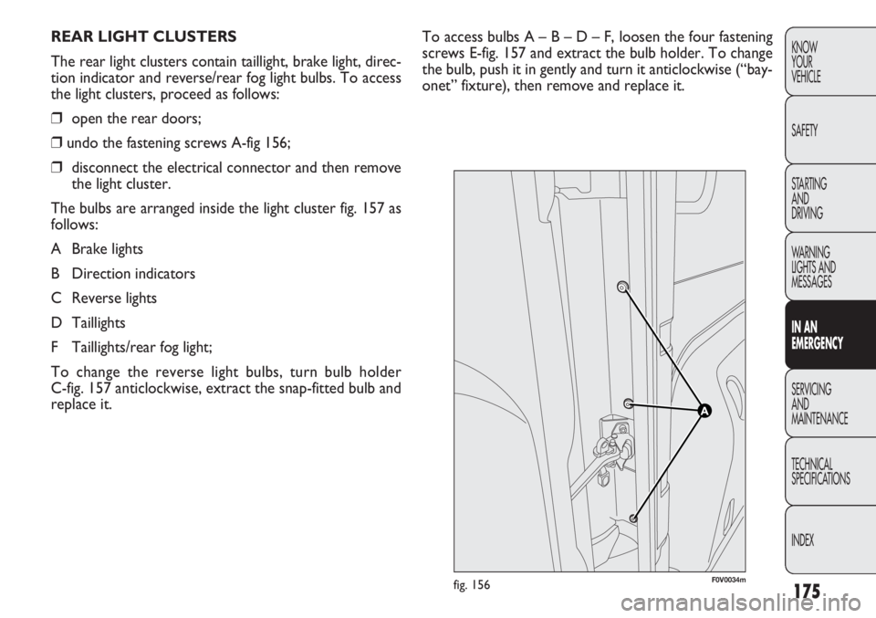
INDEXTo access bulbs A – B – D – F, loosen the four fastening
screws E-fig. 157 and extract the bulb holder. To change
the bulb, push it in gently and turn it anticlockwise (“bay-
onet” fixture), then remove and replace it.
REAR LIGHT CLUSTERS
The rear light clusters contain taillight, brake light, direc-
tion indicator and reverse/rear fog light bulbs. To access
the light clusters, proceed as follows:
❒
open the rear doors;
❒ undo the fastening screws A-fig 156;
❒ disconnect the electrical connector and then remove
the light cluster.
The bulbs are arranged inside the light cluster fig. 157 as
follows:
A Brake lights
B Direction indicators
C Reverse lights
D Taillights
F Taillights/rear fog light;
To change the reverse light bulbs, turn bulb holder
C-fig. 157 anticlockwise, extract the snap-fitted bulb and
replace it.
F0V0034mfig. 156
Page 181 of 283
177
KNOW
YOUR
VEHICLE
SAFETY
STARTING
AND
DRIVING
WARNING
LIGHTS AND
MESSAGES
IN AN
EMERGENCY
SERVICING
AND
MAINTENANCE
TECHNICAL
SPECIFICATIONS
INDEX
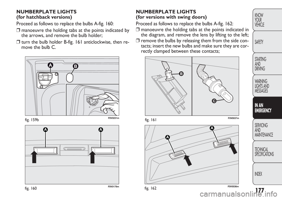
F0V0037mfig. 161
F0V0179mfig. 160
NUMBERPLATE LIGHTS
(for versions with swing doors)
Proceed as follows to replace the bulbs A-fig. 162:
❒ manoeuvre the holding tabs at the points indicated in
the diagram, and remove the lens by lifting to the left;
❒ remove the bulbs by releasing them from the side con-
tacts; insert the new bulbs and make sure they are cor-
rectly clamped between these contacts;
NUMBERPLATE LIGHTS
(for hatchback versions)
Proceed as follows to replace the bulbs A-fig. 160:
❒
manoeuvre the holding tabs at the points indicated by
the arrows, and remove the bulb holder;
❒ turn the bulb holder B-fig. 161 anticlockwise, then re-
move the bulb C.
F0V0036mfig. 162
F0V0231mfig. 159b
Page 182 of 283
178
KNOWYOUR
VEHICLE
SAFETY
STARTING AND
DRIVING
WARNING
LIGHTS AND MESSAGES
IN AN
EMERGENCY
SERVICING AND
MAINTENANCE
TECHNICAL
SPECIFICA TIONS
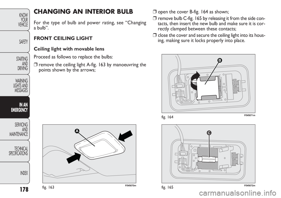
INDEX❒ open the cover B-fig. 164 as shown;
❒ remove bulb C-fig. 165 by releasing it from the side con-
tacts, then insert the new bulb and make sure it is cor-
rectly clamped between these contacts;
❒ close the cover and secure the ceiling light into its hous-
ing, making sure it locks properly into place.CHANGING AN INTERIOR BULB
For the type of bulb and power rating, see “Changing
a bulb”.
FRONT CEILING LIGHT
Ceiling light with movable lens
Proceed as follows to replace the bulbs:
❒ remove the ceiling light A-fig. 163 by manoeuvring the
points shown by the arrows;
F0V0070mfig. 163F0V0072mfig. 165
F0V0071mfig. 164
Page 183 of 283
179
KNOW
YOUR
VEHICLE
SAFETY
STARTING
AND
DRIVING
WARNING
LIGHTS AND
MESSAGES
IN AN
EMERGENCY
SERVICING
AND
MAINTENANCE
TECHNICAL
SPECIFICATIONS
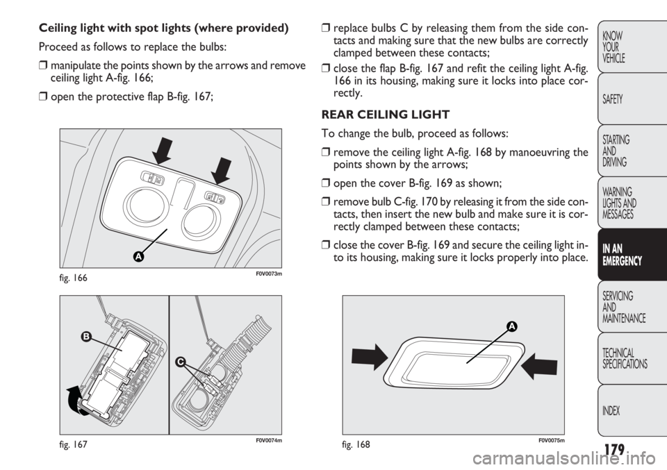
INDEX❒ replace bulbs C by releasing them from the side con-
tacts and making sure that the new bulbs are correctly
clamped between these contacts;
❒ close the flap B-fig. 167 and refit the ceiling light A-fig.
166 in its housing, making sure it locks into place cor-
rectly.
REAR CEILING LIGHT
To change the bulb, proceed as follows:
❒ remove the ceiling light A-fig. 168 by manoeuvring the
points shown by the arrows;
❒ open the cover B-fig. 169 as shown;
❒ remove bulb C-fig. 170 by releasing it from the side con-
tacts, then insert the new bulb and make sure it is cor-
rectly clamped between these contacts;
❒ close the cover B-fig. 169 and secure the ceiling light in-
to its housing, making sure it locks properly into place.
Ceiling light with spot lights (where provided)
Proceed as follows to replace the bulbs:
❒
manipulate the points shown by the arrows and remove
ceiling light A-fig. 166;
❒ open the protective flap B-fig. 167;
F0V0074mfig. 167
F0V0073mfig. 166
F0V0075mfig. 168
Page 189 of 283
185
KNOW
YOUR
VEHICLE
SAFETY
STARTING
AND
DRIVING
WARNING
LIGHTS AND
MESSAGES
IN AN
EMERGENCY
SERVICING
AND
MAINTENANCE
TECHNICAL
SPECIFICATIONS
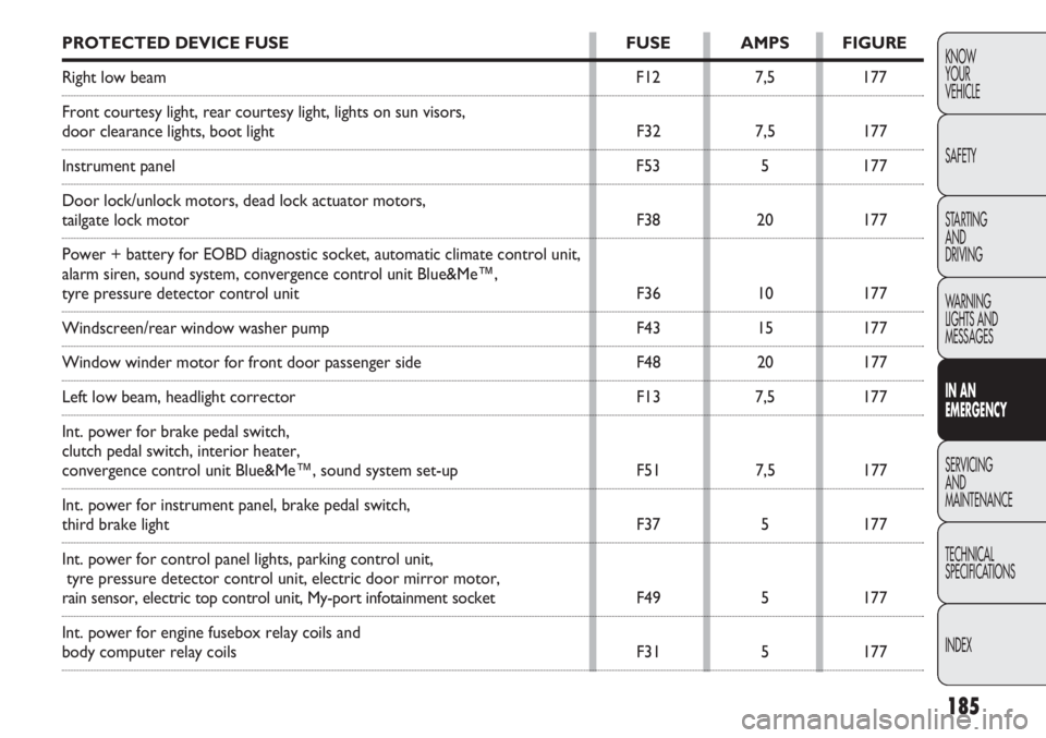
INDEXPROTECTED DEVICE FUSE FUSE AMPS FIGURE
Right low beam F127,5177
Front courtesy light, rear courtesy light, lights on sun visors,
door clearance lights, boot light F327,5177
Instrument panel F535177
Door lock/unlock motors, dead lock actuator motors,
tailgate lock motor F3820177
Power + battery for EOBD diagnostic socket, automatic climate control un\
it,
alarm siren, sound system, convergence control unit Blue&Me™,
tyre pressure detector control unit F3610177
Windscreen/rear window washer pump F4315177
Window winder motor for front door passenger side F4820177
Left low beam, headlight corrector F137,5177
Int. power for brake pedal switch,
clutch pedal switch, interior heater,
convergence control unit Blue&Me™, sound system set-up F517,5177
Int. power for instrument panel, brake pedal switch,
third brake light F375177
Int. power for control panel lights, parking control unit, tyre pressure detector control unit, electric door mirror motor,
rain sensor, electric top control unit, My-port infotainment socket F495177
Int. power for engine fusebox relay coils and
body computer relay coils F315177
Page 194 of 283
190
KNOWYOUR
VEHICLE
SAFETY
STARTING AND
DRIVING
WARNING
LIGHTS AND MESSAGES
IN AN
EMERGENCY
SERVICING AND
MAINTENANCE
TECHNICAL
SPECIFICA TIONS
INDEX
F0V0051mfig. 179
Before towing, turn the ignition key to
MAR and then to STOP without extract-
ing it. The steering column will automatically lock
when the key is removed, making it impossible to
turn the wheels.
WARNING
Before tightening the ring, clean the
threaded housing thoroughly. Before tow-
ing the vehicle, make sure that the tow ring is ful-
ly tightened in its appropriate housing.
Never start the engine when the vehicle is being
towed.
WARNING
Remember that, while being towed, you
will need to brake harder because there
will be no assistance from the brake booster. Do
not use bendy cables for towing and avoid jerking.
During towing operations, make sure that the fas-
tened joint does not damage adjoining compo-
nents. When towing the vehicle, comply with the
specific rules of the highway code regarding the
towing device and road conduct. Do not start the
engine while being towed.
WARNING
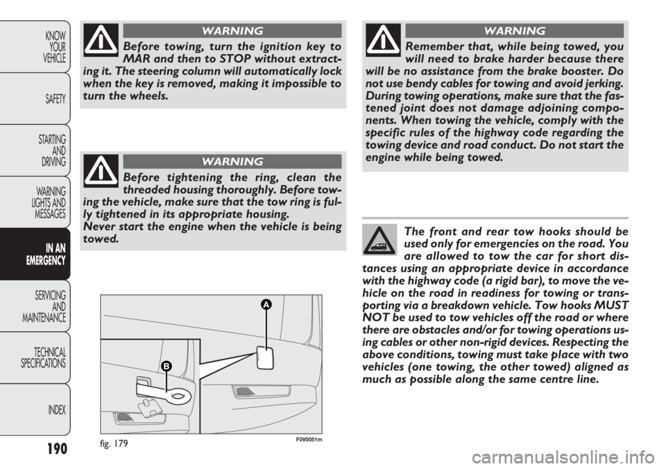
The front and rear tow hooks should be
used only for emergencies on the road. You
are allowed to tow the car for short dis-
tances using an appropriate device in accordance
with the highway code (a rigid bar), to move the ve-
hicle on the road in readiness for towing or trans-
porting via a breakdown vehicle. Tow hooks MUST
NOT be used to tow vehicles off the road or where
there are obstacles and/or for towing operations us-
ing cables or other non-rigid devices. Respecting the
above conditions, towing must take place with two
vehicles (one towing, the other towed) aligned as
much as possible along the same centre line.