Lock on dashboard FIAT DUCATO 2007 3.G Owner's Manual
[x] Cancel search | Manufacturer: FIAT, Model Year: 2007, Model line: DUCATO, Model: FIAT DUCATO 2007 3.GPages: 282, PDF Size: 4.71 MB
Page 59 of 282
58
SAFETY
DEVICES
CORRECT USE
OF THE
VEHICLE
WARNING
LIGHTS AND
MESSAGES
IN AN
EMERGENCY
VEHICLE
MAINTENANCE
TECHNICAL
SPECIFICATIONS
INDEX
DASHBOARD
AND CONTROLS
CONTROLS
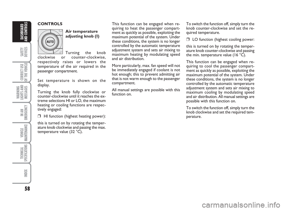
Air temperature
adjusting knob (I)
temperatura
Turning the knob
clockwise or counter-clockwise,
respectively raises or lowers the
temperature of the air required in the
passenger compartment.
Set temperature is shown on the
display.
Turning the knob fully clockwise or
counter-clockwise until it reaches the ex-
treme selections HI or LO, the maximum
heating or cooling functions are respec-
tively engaged:
❒HI function (highest heating power):
this is turned on by rotating the temper-
ature knob clockwise and passing the max.
temperature value (32 °C).
This function can be engaged when re-
quiring to heat the passenger compart-
ment as quickly as possible, exploiting the
maximum potential of the system. Under
these conditions, the system is no longer
controlled by the automatic temperature
adjustment system and sets air mixing to
maximum heating by modulating speed
and air distribution.
More particularly, max. fan speed will not
be immediately engaged if coolant is not
hot enough; this to prevent admitting air
that is not warm enough to the passenger
compartment.
All manual settings are possible with this
function on.To switch the function off, simply turn the
knob counter-clockwise and set the re-
quired temperature.
❒LO function (highest cooling power:
this is turned on by rotating the temper-
ature knob counter-clockwise and passing
the min. temperature value (16 °C).
This function can be engaged when re-
quiring to cool the passenger compart-
ment as quickly as possible, exploiting the
maximum potential of the system. Under
these conditions, the system is no longer
controlled by the automatic temperature
adjustment system and sets air mixing to
maximum cooling by modulating speed
and air distribution. All manual settings are
possible with this function on.
To switch the function off, simply turn the
knob clockwise and set the required tem-
perature.
037-101 Ducato GB 6-11-2007 9:56 Pagina 58
Page 67 of 282
66
SAFETY
DEVICES
CORRECT USE
OF THE
VEHICLE
WARNING
LIGHTS AND
MESSAGES
IN AN
EMERGENCY
VEHICLE
MAINTENANCE
TECHNICAL
SPECIFICATIONS
INDEX
DASHBOARD
AND CONTROLS
SELF-STANDING
SUPPLEMENTARY
HEATER
(where provided)
Fiat Ducato can be equipped, upon re-
quest, with two different self-standing
heaters: one is totally automatic whereas
the other is programmable.
AUTOMATIC VERSION
The supplementary heater will activate au-
tomatically with engine turned on and
proper engine coolant and outside tem-
perature conditions. Deactivation is always
automatic.
IMPORTANT During periods of low tem-
perature when the device is activated,
check that the fuel level is higher than the
reserve. Otherwise the device could lock
and require the assistance of the Fiat
Dealership.PROGRAMMABLE VERSION
The supplementary heater is totally inde-
pendent from the engine and can be used
to:
❒heat the passenger compartment
when the engine is off;
❒defrost the windows;
❒heat the engine coolant and conse-
quently the engine before starting.The system consists of:
❒diesel burner to heat coolant with ex-
haust fume muffler;
❒metering pump connected to the ve-
hicle fuel pipes to feed the burner;
❒heat exchanger connected to the en-
gine cooling system pipes;
The heater burns fuel in the
same way as the engine,
though, of course, to a lesser degree
and therefore to avoid intoxication
and suffocation, never use the sup-
plementary heater in closed areas,
garages or workshops not equipped
with specific exhaust evacuation de-
vices even for short periods of time.
WARNING
037-101 Ducato GB 6-11-2007 9:56 Pagina 66
Page 69 of 282
68
SAFETY
DEVICES
CORRECT USE
OF THE
VEHICLE
WARNING
LIGHTS AND
MESSAGES
IN AN
EMERGENCY
VEHICLE
MAINTENANCE
TECHNICAL
SPECIFICATIONS
INDEX
DASHBOARD
AND CONTROLS
IMPORTANT The heater is equipped with
a thermal switch which cuts off the heater
in the event of overheating caused by low
or leaking coolant. In this case, press the
program selection button to start the
heater again after repairing the cooling sys-
tem fault and/or topping up the fluid.
The heater can turn itself off after engine
ignition or if the flame goes out. In this
case, turn the heater off manually and at-
tempt to turn it back on again. If you can-
not turn the heater on, contact a Fiat
Dealership.Turning the heater on
If an automatic climate control system is
fitted, the control unit sets air tempera-
ture and distribution when the parking
heater is turned on.
When a manual heater/climate control
system is fitted, to achieve peak heater
performance, check that the passenger
compartment heater/ventilation unit air
temperature knob is in “warm air” posi-
tion.
For preferential passenger compartment
preheating, turn the air distribution knob
to position
©.
For preferential windscreen demisting, set
the air distribution knob to position
-.
To obtain both functions, set the air dis-
tribution knob to position
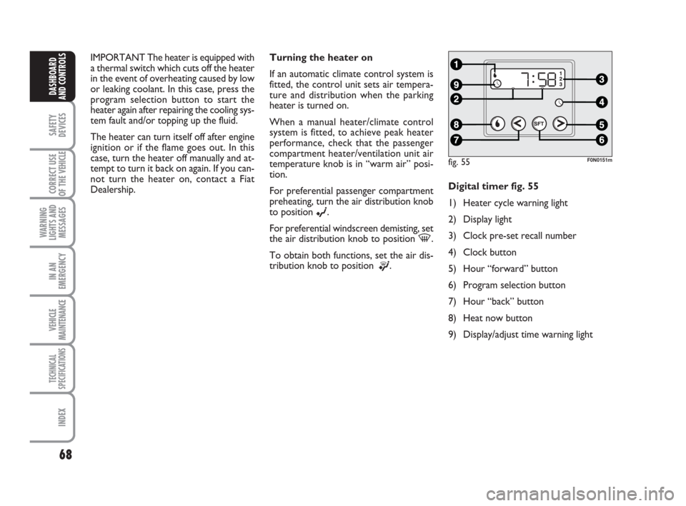
®.Digital timer fig. 55
1) Heater cycle warning light
2) Display light
3) Clock pre-set recall number
4) Clock button
5) Hour “forward” button
6) Program selection button
7) Hour “back” button
8) Heat now button
9) Display/adjust time warning light
fig. 55F0N0151m
037-101 Ducato GB 6-11-2007 9:56 Pagina 68
Page 70 of 282
69
SAFETY
DEVICES
CORRECT USE
OF THE
VEHICLE
WARNING
LIGHTS AND
MESSAGES
IN AN
EMERGENCY
VEHICLE
MAINTENANCE
TECHNICAL
SPECIFICATIONS
INDEX
DASHBOARD
AND CONTROLS
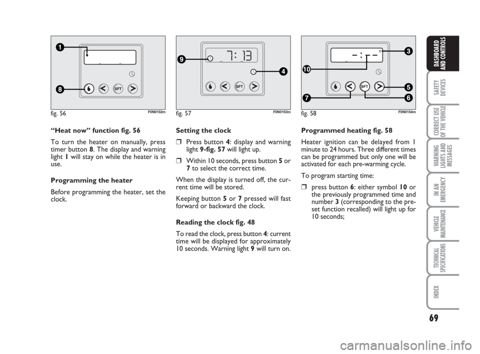
Programmed heating fig. 58
Heater ignition can be delayed from 1
minute to 24 hours. Three different times
can be programmed but only one will be
activated for each pre-warming cycle.
To program starting time:
❒press button 6: either symbol 10 or
the previously programmed time and
number 3 (corresponding to the pre-
set function recalled) will light up for
10 seconds; Setting the clock
❒Press button 4: display and warning
light 9-fig. 57will light up.
❒Within 10 seconds, press button 5or
7to select the correct time.
When the display is turned off, the cur-
rent time will be stored.
Keeping button 5or 7pressed will fast
forward or backward the clock.
Reading the clock fig. 48
To read the clock, press button 4: current
time will be displayed for approximately
10 seconds. Warning light 9will turn on. “Heat now” function fig. 56
To turn the heater on manually, press
timer button 8. The display and warning
light 1will stay on while the heater is in
use.
Programming the heater
Before programming the heater, set the
clock.
fig. 56F0N0152mfig. 57F0N0153mfig. 58F0N0154m
037-101 Ducato GB 6-11-2007 9:56 Pagina 69
Page 72 of 282
71
SAFETY
DEVICES
CORRECT USE
OF THE
VEHICLE
WARNING
LIGHTS AND
MESSAGES
IN AN
EMERGENCY
VEHICLE
MAINTENANCE
TECHNICAL
SPECIFICATIONS
INDEX
DASHBOARD
AND CONTROLS
❒Always remember to turn the heater
off when refuelling or standing in ser-
vice stations to avoid fires and explo-
sions.
❒Do not park the vehicle over inflam-
mable material such as paper, dry grass
or leaves: fire risk!
❒The temperature near the heater must
never exceed 120°C (e.g. during paint-
ing operations in a workshop oven).
Higher temperatures could damage
the electronic control unit compo-
nents.
❒When the engine is off, the heater takes
power from the battery: it is conse-
quently important to run the engine for
a certain period of time in order to re-
store the battery charge.
❒Follow the prescriptions in section
“Vehicle maintenance” at paragraph
“Engine coolant level” to check the
coolant level. The coolant in the cir-
cuit must contain at least 10% an-
tifreeze fluid.
❒Maintenance and repairs must always
be carried out by a Fiat Dealership and
only genuine spare parts must be used.
MAINTENANCE
Have the heater checked at a Fiat Deal-
ership periodically (always before winter).
This will ensure safe and cheap running
and long appliance life.
The heater burns fuel in the
same way as the engine,
though, of course, to a lesser degree
and therefore to avoid intoxication
and suffocation, never use the sup-
plementary heater in closed areas,
garages or workshops not equipped
with specific exhaust evacuation de-
vices even for short periods of time.
WARNING
IMPORTANT The parking heater goes off
when the battery voltage is low to enable
the vehicle to be started up.
IMPORTANT Before turning on the de-
vice, ensure that the fuel level is higher
than the reserve. Otherwise the device
could lock and require the assistance of
the Fiat Dealership.
037-101 Ducato GB 6-11-2007 9:56 Pagina 71
Page 82 of 282
81
SAFETY
DEVICES
CORRECT USE
OF THE
VEHICLE
WARNING
LIGHTS AND
MESSAGES
IN AN
EMERGENCY
VEHICLE
MAINTENANCE
TECHNICAL
SPECIFICATIONS
INDEX
DASHBOARD
AND CONTROLS
CEILING LIGHTS
FRONT CEILING LIGHT WITH
SPOT LIGHTS
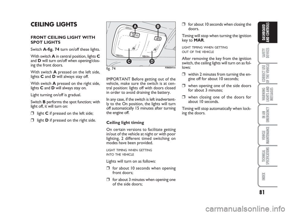
Switch A-fig. 74turn on/off these lights.
With switch A in central position, lights C
and Dwill turn on/off when opening/clos-
ing the front doors.
With switch Apressed on the left side,
lights Cand Dwill always stay off.
With switch Apressed on the right side,
lights Cand Dwill always stay on.
Light turning on/off is gradual.
Switch Bperforms the spot function; with
light off, it will turn on:
❒light Cif pressed on the left side;
❒light Dif pressed on the right side.IMPORTANT Before getting out of the
vehicle, make sure the switch is at cen-
tral position: lights off with doors closed
in order to avoid draining the battery.
In any case, if the switch is left inadvertent-
ly to the On position, the lights will turn
off automatically 15 minutes after turning
the engine off.
Ceiling light timing
On certain versions to facilitate getting
in/out of the vehicle at night or with poor
lighting, 2 different timed switching on
modes have been provided.
LIGHT TIMING WHEN GETTING
INTO THE VEHICLE
Lights will turn on as follows:
❒for about 10 seconds when opening
front doors;
❒for about 3 minutes when opening one
of the side doors;
❒for about 10 seconds when closing the
doors.
Timing will stop when turning the ignition
key to MAR.
LIGHT TIMING WHEN GETTING
OUT OF THE VEHICLE
After removing the key from the ignition
switch, the ceiling lights will turn on as fol-
lows:
❒within 2 minutes from turning the en-
gine off for about 10 seconds;
❒when opening one of the side doors
for about 3 minutes;
❒when closing one of the doors for
about 10 seconds.
Timing will stop automatically when lock-
ing the doors.
fig. 74F0N0041m
037-101 Ducato GB 6-11-2007 9:56 Pagina 81
Page 85 of 282
84
SAFETY
DEVICES
CORRECT USE
OF THE
VEHICLE
WARNING
LIGHTS AND
MESSAGES
IN AN
EMERGENCY
VEHICLE
MAINTENANCE
TECHNICAL
SPECIFICATIONS
INDEX
DASHBOARD
AND CONTROLS
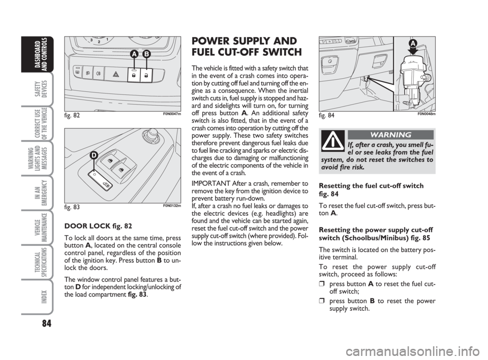
DOOR LOCK fig. 82
To lock all doors at the same time, press
button A, located on the central console
control panel, regardless of the position
of the ignition key. Press button Bto un-
lock the doors.
The window control panel features a but-
ton Dfor independent locking/unlocking of
the load compartment fig. 83.
POWER SUPPLY AND
FUEL CUT-OFF SWITCH
The vehicle is fitted with a safety switch that
in the event of a crash comes into opera-
tion by cutting off fuel and turning off the en-
gine as a consequence. When the inertial
switch cuts in, fuel supply is stopped and haz-
ard and sidelights will turn on, for turning
off press button A. An additional safety
switch is also fitted, that in the event of a
crash comes into operation by cutting off the
power supply. These two safety switches
therefore prevent dangerous fuel leaks due
to fuel line cracking and sparks or electric dis-
charges due to damaging or malfunctioning
of the electric components of the vehicle in
the event of a crash.
IMPORTANT After a crash, remember to
remove the key from the ignition device to
prevent battery run-down.
If, after a crash no fuel leaks or damages to
the electric devices (e.g. headlights) are
found and the vehicle can be started again,
reset the fuel cut-off switch and the power
supply cut-off switch (where provided). Fol-
low the instructions given below.
fig. 82F0N0047mfig. 84F0N0048m
If, after a crash, you smell fu-
el or see leaks from the fuel
system, do not reset the switches to
avoid fire risk.
WARNING
Resetting the fuel cut-off switch
fig. 84
To reset the fuel cut-off switch, press but-
ton A.
Resetting the power supply cut-off
switch (Schoolbus/Minibus) fig. 85
The switch is located on the battery pos-
itive terminal.
To reset the power supply cut-off
switch, proceed as follows:
❒press button Ato reset the fuel cut-
off switch;
❒press button Bto reset the power
supply switch.
fig. 83F0N0132m
037-101 Ducato GB 6-11-2007 9:56 Pagina 84
Page 86 of 282
85
SAFETY
DEVICES
CORRECT USE
OF THE
VEHICLE
WARNING
LIGHTS AND
MESSAGES
IN AN
EMERGENCY
VEHICLE
MAINTENANCE
TECHNICAL
SPECIFICATIONS
INDEX
DASHBOARD
AND CONTROLS
fig. 85F0N0127m
fig. 87F0N0050m
fig. 86F0N0049m
fig. 88F0N0051m
INTERIOR EQUIPMENT
UPPER ODDMENT
COMPARTMENT -
REFRIGERATED
COMPARTMENT
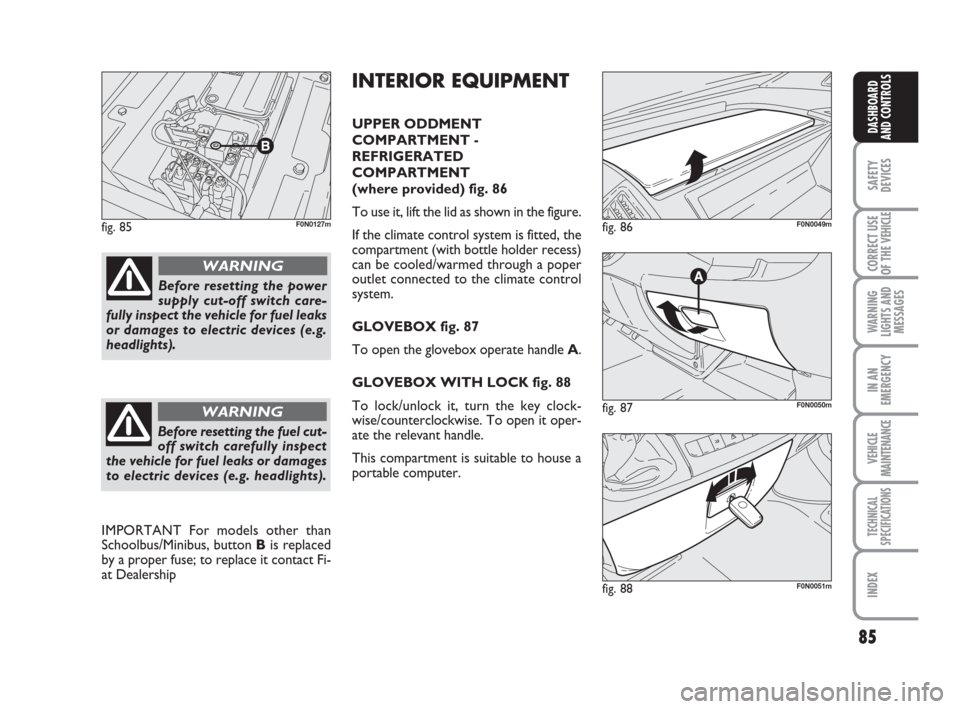
(where provided) fig. 86
To use it, lift the lid as shown in the figure.
If the climate control system is fitted, the
compartment (with bottle holder recess)
can be cooled/warmed through a poper
outlet connected to the climate control
system.
GLOVEBOX fig. 87
To open the glovebox operate handle A.
GLOVEBOX WITH LOCK fig. 88
To lock/unlock it, turn the key clock-
wise/counterclockwise. To open it oper-
ate the relevant handle.
This compartment is suitable to house a
portable computer.
Before resetting the power
supply cut-off switch care-
fully inspect the vehicle for fuel leaks
or damages to electric devices (e.g.
headlights).
WARNING
Before resetting the fuel cut-
off switch carefully inspect
the vehicle for fuel leaks or damages
to electric devices (e.g. headlights).
WARNING
IMPORTANT For models other than
Schoolbus/Minibus, button Bis replaced
by a proper fuse; to replace it contact Fi-
at Dealership
037-101 Ducato GB 6-11-2007 9:56 Pagina 85
Page 87 of 282
86
SAFETY
DEVICES
CORRECT USE
OF THE
VEHICLE
WARNING
LIGHTS AND
MESSAGES
IN AN
EMERGENCY
VEHICLE
MAINTENANCE
TECHNICAL
SPECIFICATIONS
INDEX
DASHBOARD
AND CONTROLS
fig. 90F0N0053m
fig. 89F0N0052mfig. 92F0N0134mfig. 91F0N0128m
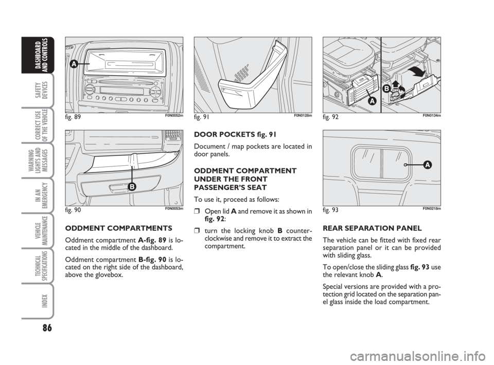
ODDMENT COMPARTMENTS
Oddment compartment A-fig. 89is lo-
cated in the middle of the dashboard.
Oddment compartment B-fig. 90is lo-
cated on the right side of the dashboard,
above the glovebox.DOOR POCKETS fig. 91
Document / map pockets are located in
door panels.
ODDMENT COMPARTMENT
UNDER THE FRONT
PASSENGER’S SEAT
To use it, proceed as follows:
❒Open lid Aand remove it as shown in
fig. 92:
❒turn the locking knob Bcounter-
clockwise and remove it to extract the
compartment.REAR SEPARATION PANEL
The vehicle can be fitted with fixed rear
separation panel or it can be provided
with sliding glass.
To open/close the sliding glass fig. 93use
the relevant knob A.
Special versions are provided with a pro-
tection grid located on the separation pan-
el glass inside the load compartment.
fig. 93F0N0218m
037-101 Ducato GB 6-11-2007 9:56 Pagina 86
Page 93 of 282
92
SAFETY
DEVICES
CORRECT USE
OF THE
VEHICLE
WARNING
LIGHTS AND
MESSAGES
IN AN
EMERGENCY
VEHICLE
MAINTENANCE
TECHNICAL
SPECIFICATIONS
INDEX
DASHBOARD
AND CONTROLS
IMPORTANT
Do not use abrasive detergents or sol-
vents to clean the device. To clean its ex-
ternal surface, use a wet cloth or special
products for cleaning synthetic materials.
The multimeter is installed and sealed with
lead by authorised personnel: access to
the device and relevant power and record-
ing cables is forbidden.
The vehicle owner is responsible for gov-
erning the instrument use. The inspection
must be carried out at least every two
years and will include a test to confirm
correct operation.
After the inspection, check that the plate
is updated with specified data.DOORS
CENTRAL DOOR
LOCKING/UNLOCKING SYSTEM
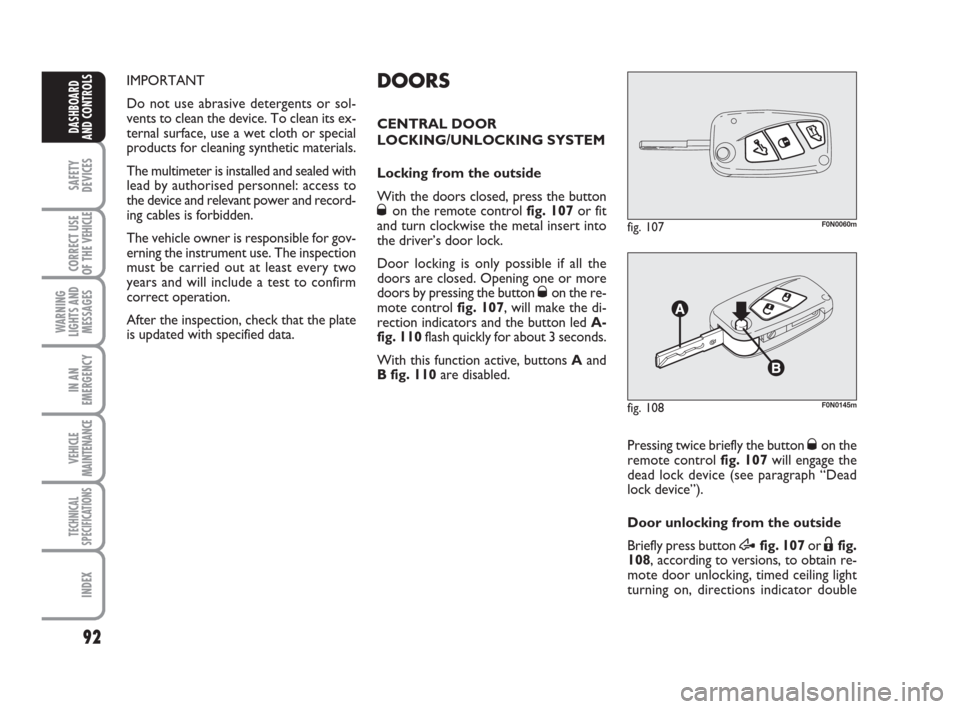
Locking from the outside
With the doors closed, press the button
Øon the remote control fig. 107or fit
and turn clockwise the metal insert into
the driver’s door lock.
Door locking is only possible if all the
doors are closed. Opening one or more
doors by pressing the button
Øon the re-
mote control fig. 107, will make the di-
rection indicators and the button led A-
fig. 110flash quickly for about 3 seconds.
With this function active, buttons Aand
B fig. 110are disabled.
fig. 107F0N0060m
Pressing twice briefly the button Øon the
remote control fig. 107will engage the
dead lock device (see paragraph “Dead
lock device”).
Door unlocking from the outside
Briefly press button
Æfig. 107or Ëfig.
108, according to versions, to obtain re-
mote door unlocking, timed ceiling light
turning on, directions indicator double
fig. 108F0N0145m
037-101 Ducato GB 6-11-2007 9:56 Pagina 92