Rear lights function FIAT DUCATO 2007 Owner handbook (in English)
[x] Cancel search | Manufacturer: FIAT, Model Year: 2007, Model line: DUCATO, Model: FIAT DUCATO 2007Pages: 282, PDF Size: 4.49 MB
Page 5 of 282
4
SAFETY
DEVICES
CORRECT USE
OF THE
VEHICLE
WARNING
LIGHTS AND
MESSAGES
IN AN
EMERGENCY
VEHICLE
MAINTENANCE
TECHNICAL
SPECIFICATIONS
INDEX
DASHBOARD
AND CONTROLSDASHBOARD (LEFT HAND DRIVE VERSION) .......... 5
DASHBOARD (RIGHT HAND DRIVE VERSION) ...... 6
SYMBOLS ................................................................................. 7
THE FIAT CODE SYSTEM ................................................... 7
THE KEYS ................................................................................ 8
ELECTRONIC ALARM ......................................................... 13
IGNITION DEVICE ................................................................ 15
INSTRUMENT PANEL (LEFT HAND DRIVE VERSION) 16
INSTRUMENT PANEL (RIGHT HAND DRIVE VERSION) 17
INSTRUMENTS ....................................................................... 18
DIGITAL DISPLAY ................................................................ 21
MULTIFUNCTION DISPLAY ............................................. 26
TRIP COMPUTER ................................................................. 35
FRONT SEATS ....................................................................... 37
HEAD RESTRAINTS .............................................................. 43
STEERING WHEEL ............................................................... 44
REARVIEW MIRRORS ........................................................... 45
HEATING AND VENTILATION ....................................... 47
MANUAL CLIMATE CONTROL SYSTEM .................... 51
AUTOMATIC CLIMATE CONTROL SYSTEM .............. 55
SUPPLEMENTARY HEATER .............................................. 65
SELF-STANDING SUPPLEMENTARY HEATER............. 66
SUPPLEMENTARY REAR HEATER ................................... 72SUPPLEMENTARY REAR AIR CONDITIONER ............ 73
EXTERNAL LIGHTS .............................................................. 74
WINDOW WASHING......................................................... 77
CRUISE CONTROL ............................................................. 79
CEILING LIGHTS .................................................................. 81
CONTROLS ........................................................................... 82
POWER SUPPLY AND FUEL CUT-OFF SWITCH....... 84
INTERIOR FITTINGS ............................................................ 85
MULTIMETER .......................................................................... 91
DOORS .................................................................................... 92
POWER WINDOWS/WINDOW WINDERS .............. 97
BONNET .................................................................................. 98
ROOF RACK/SKI RACK ..................................................... 100
HEADLIGHTS .......................................................................... 101
ABS SYSTEM ........................................................................... 102
ESP SYSTEM ............................................................................ 103
EOBD SYSTEM ....................................................................... 106
PARKING SENSORS ............................................................ 107
SOUND SYSTEM .................................................................... 108
ACCESSORIES PURCHASED BY THE OWNER .......... 109
AT THE FILLING STATION .............................................. 110
PROTECTING THE ENVIRONMENT ............................. 112
D D
A A
S S
H H
B B
O O
A A
R R
D D
A A
N N
D D
C C
O O
N N
T T
R R
O O
L L
S S
Page 6 of 282
5
SAFETY
DEVICES
CORRECT USE
OF THE
VEHICLE
WARNING
LIGHTS AND
MESSAGES
IN AN
EMERGENCY
VEHICLE
MAINTENANCE
TECHNICAL
SPECIFICATIONS
INDEX
DASHBOARD
AND CONTROLS
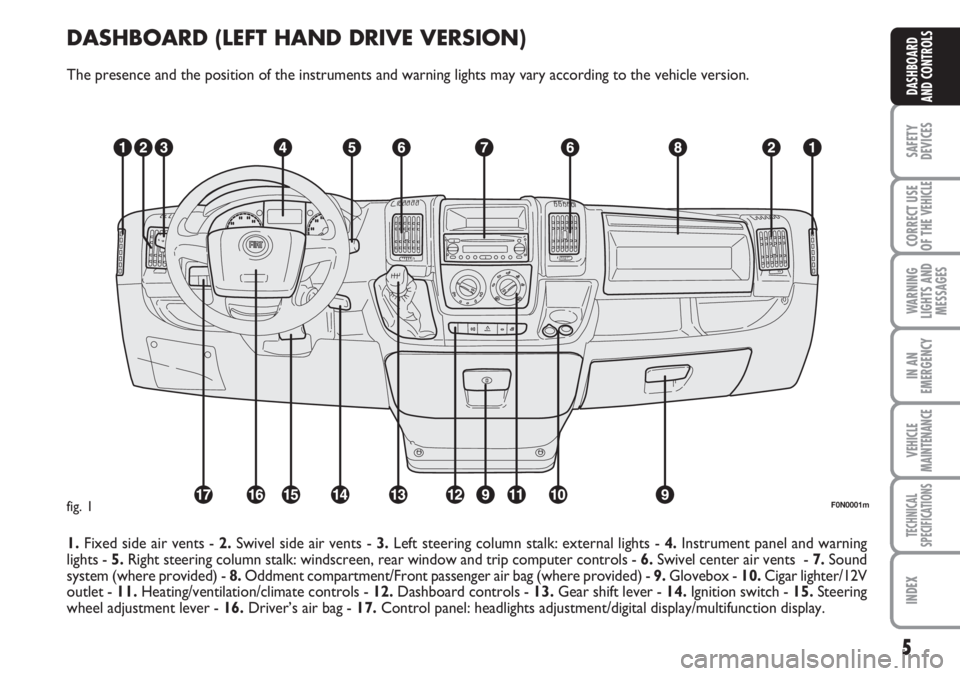
DASHBOARD (LEFT HAND DRIVE VERSION)
The presence and the position of the instruments and warning lights may vary according to the vehicle version.
1.Fixed side air vents - 2.Swivel side air vents - 3.Left steering column stalk: external lights - 4.Instrument panel and warning
lights - 5.Right steering column stalk: windscreen, rear window and trip computer controls - 6.Swivel center air vents - 7.Sound
system (where provided) - 8.Oddment compartment/Front passenger air bag (where provided) - 9.Glovebox - 10.Cigar lighter/12V
outlet - 11.Heating/ventilation/climate controls - 12.Dashboard controls - 13.Gear shift lever - 14.Ignition switch - 15. Steering
wheel adjustment lever - 16.Driver’s air bag - 17.Control panel: headlights adjustment/digital display/multifunction display.
F0N0001mfig. 1
Page 7 of 282
6
SAFETY
DEVICES
CORRECT USE
OF THE
VEHICLE
WARNING
LIGHTS AND
MESSAGES
IN AN
EMERGENCY
VEHICLE
MAINTENANCE
TECHNICAL
SPECIFICATIONS
INDEX
DASHBOARD
AND CONTROLS
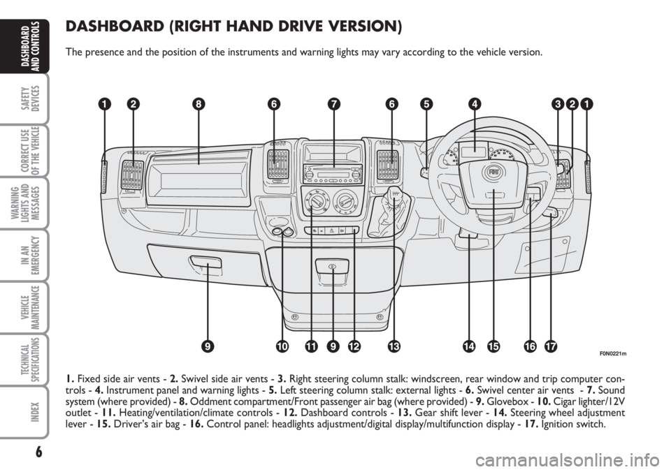
DASHBOARD (RIGHT HAND DRIVE VERSION)
The presence and the position of the instruments and warning lights may vary according to the vehicle version.
F0N0221m
1.Fixed side air vents - 2.Swivel side air vents - 3.Right steering column stalk: windscreen, rear window and trip computer con-
trols - 4.Instrument panel and warning lights - 5.Left steering column stalk: external lights - 6.Swivel center air vents - 7.Sound
system (where provided) - 8.Oddment compartment/Front passenger air bag (where provided) - 9.Glovebox - 10.Cigar lighter/12V
outlet - 11.Heating/ventilation/climate controls - 12.Dashboard controls - 13.Gear shift lever - 14. Steering wheel adjustment
lever - 15.Driver’s air bag - 16.Control panel: headlights adjustment/digital display/multifunction display - 17.Ignition switch.
Page 41 of 282
40
SAFETY
DEVICES
CORRECT USE
OF THE
VEHICLE
WARNING
LIGHTS AND
MESSAGES
IN AN
EMERGENCY
VEHICLE
MAINTENANCE
TECHNICAL
SPECIFICATIONS
INDEX
DASHBOARD
AND CONTROLS
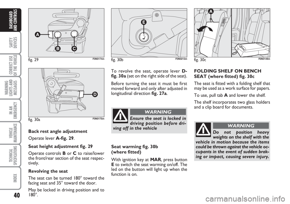
Back rest angle adjustment
Operate lever A-fig. 29.
Seat height adjustment fig. 29
Operate controls Bor Cto raise/lower
the front/rear section of the seat respec-
tively.
Revolving the seat
The seat can be turned 180° toward the
facing seat and 35° toward the door.
May be locked in driving position and to
180°.
fig. 29F0N0174m
fig. 30aF0N0175m
To revolve the seat, operate lever D-
fig. 30a(set on the right side of the seat).
Before turning the seat it must be first
moved forward and only after adjusted in
longitudinal direction fig. 27a.
fig. 30bF0N0213m
Ensure the seat is locked in
driving position before dri-
ving off in the vehicle
WARNING
Seat warming fig. 30b
(where fitted)
With ignition key at MAR, press button
Eto switch the seat warming on/off. The
led on the button will light up when the
function is on.
fig. 30cF0N0149m
FOLDING SHELF ON BENCH
SEAT (where fitted) fig. 30c
The seat is fitted with a folding shelf that
may be used as a work surface for papers.
To use, pull tab Aand lower the shelf.
The shelf incorporates two glass holders
and a clip board for documents.
Do not position heavy
weights on the shelf with the
vehicle in motion because the items
could be thrown against the vehicle oc-
cupants in the event of sudden brak-
ing or impact, causing severe injury.
WARNING
Page 47 of 282
46
SAFETY
DEVICES
CORRECT USE
OF THE
VEHICLE
WARNING
LIGHTS AND
MESSAGES
IN AN
EMERGENCY
VEHICLE
MAINTENANCE
TECHNICAL
SPECIFICATIONS
INDEX
DASHBOARD
AND CONTROLS
Folding
When required (for example when the
mirror causes difficulty in narrow spaces)
it is possible to fold the mirror moving it
from position 1-fig. 40to position 2.
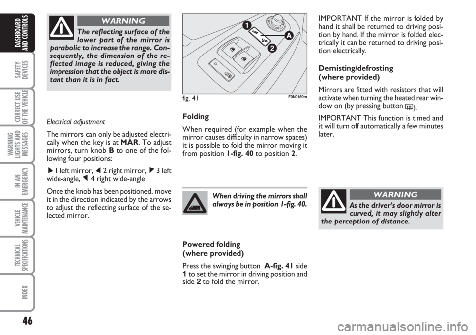
Powered folding
(where provided)
Press the swinging button A-fig. 41side
1to set the mirror in driving position and
side 2to fold the mirror.When driving the mirrors shall
always be in position 1-fig. 40.
As the driver’s door mirror is
curved, it may slightly alter
the perception of distance.
WARNING
IMPORTANT If the mirror is folded by
hand it shall be returned to driving posi-
tion by hand. If the mirror is folded elec-
trically it can be returned to driving posi-
tion electrically.
Demisting/defrosting
(where provided)
Mirrors are fitted with resistors that will
activate when turning the heated rear win-
dow on (by pressing button
().
IMPORTANT This function is timed and
it will turn off automatically a few minutes
later. The reflecting surface of the
lower part of the mirror is
parabolic to increase the range. Con-
sequently, the dimension of the re-
flected image is reduced, giving the
impression that the object is more dis-
tant than it is in fact.
WARNING
Electrical adjustment
The mirrors can only be adjusted electri-
cally when the key is at MAR. To adjust
mirrors, turn knob Bto one of the fol-
lowing four positions:
ÿ1 left mirror, ⁄2 right mirror, ¤3 left
wide-angle, Ÿ4 right wide-angle
Once the knob has been positioned, move
it in the direction indicated by the arrows
to adjust the reflecting surface of the se-
lected mirror.
fig. 41F0N0159m
Page 51 of 282
50
SAFETY
DEVICES
CORRECT USE
OF THE
VEHICLE
WARNING
LIGHTS AND
MESSAGES
IN AN
EMERGENCY
VEHICLE
MAINTENANCE
TECHNICAL
SPECIFICATIONS
INDEX
DASHBOARD
AND CONTROLS
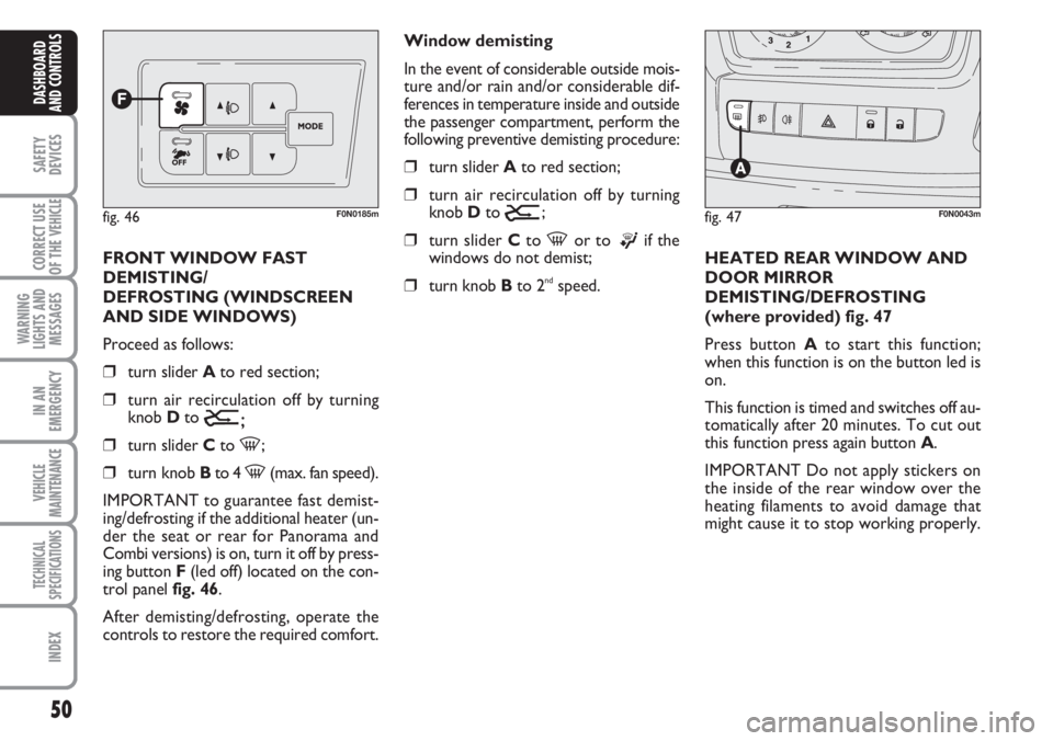
FRONT WINDOW FAST
DEMISTING/
DEFROSTING (WINDSCREEN
AND SIDE WINDOWS)
Proceed as follows:
❒turn slider Ato red section;
❒turn air recirculation off by turning
knob D to
Ú;
❒turn slider Cto -;
❒turn knob Bto 4 -(max. fan speed).
IMPORTANT to guarantee fast demist-
ing/defrosting if the additional heater (un-
der the seat or rear for Panorama and
Combi versions) is on, turn it off by press-
ing button F(led off) located on the con-
trol panel fig. 46.
After demisting/defrosting, operate the
controls to restore the required comfort.Window demisting
In the event of considerable outside mois-
ture and/or rain and/or considerable dif-
ferences in temperature inside and outside
the passenger compartment, perform the
following preventive demisting procedure:
❒turn slider Ato red section;
❒turn air recirculation off by turning
knob D to
Ú;
❒turn slider Cto -or to ®if the
windows do not demist;
❒turn knob Bto 2ndspeed.HEATED REAR WINDOW AND
DOOR MIRROR
DEMISTING/DEFROSTING
(where provided) fig. 47
Press button Ato start this function;
when this function is on the button led is
on.
This function is timed and switches off au-
tomatically after 20 minutes. To cut out
this function press again button A.
IMPORTANT Do not apply stickers on
the inside of the rear window over the
heating filaments to avoid damage that
might cause it to stop working properly.
fig. 46F0N0185mfig. 47F0N0043m
Page 55 of 282
54
SAFETY
DEVICES
CORRECT USE
OF THE
VEHICLE
WARNING
LIGHTS AND
MESSAGES
IN AN
EMERGENCY
VEHICLE
MAINTENANCE
TECHNICAL
SPECIFICATIONS
INDEX
DASHBOARD
AND CONTROLS
After demisting/defrosting, operate the
controls to keep the required comfort.
IMPORTANT The climate control system
is very useful to speed up demisting since
it dehumidifies the air. Set controls to
demisting function and switch on the cli-
mate control system by pressing button
E; the knob led will turn on.
Window demisting
In the event of considerable outside mois-
ture and/or rain and/or considerable dif-
ferences in temperature inside and outside
the passenger compartment, perform the
following preventive demisting procedure:
❒turn slider Ato red section;
❒turn air recirculation off by turning
knob Dto
Ú;
❒turn slider Cto -or to ®if the
windows do not demist;
❒turn knob Bto 2nd speed.
fig. 49F0N0185m
IMPORTANT The climate control system
is very useful to prevent window misting
up in presence of high humidity since it de-
humidifies the air.
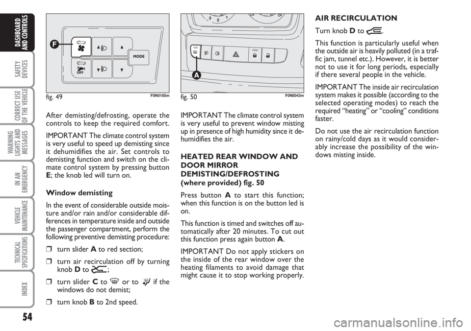
HEATED REAR WINDOW AND
DOOR MIRROR
DEMISTING/DEFROSTING
(where provided) fig. 50
Press button Ato start this function;
when this function is on the button led is
on.
This function is timed and switches off au-
tomatically after 20 minutes. To cut out
this function press again button A.
IMPORTANT Do not apply stickers on
the inside of the rear window over the
heating filaments to avoid damage that
might cause it to stop working properly.AIR RECIRCULATION
Turn knob Dto
Ò.
This function is particularly useful when
the outside air is heavily polluted (in a traf-
fic jam, tunnel etc.). However, it is better
not to use it for long periods, especially
if there several people in the vehicle.
IMPORTANT The inside air recirculation
system makes it possible (according to the
selected operating modes) to reach the
required “heating” or “cooling” conditions
faster.
Do not use the air recirculation function
on rainy/cold days as it would consider-
ably increase the possibility of the win-
dows misting inside.
fig. 50F0N0043m
Page 58 of 282
57
SAFETY
DEVICES
CORRECT USE
OF THE
VEHICLE
WARNING
LIGHTS AND
MESSAGES
IN AN
EMERGENCY
VEHICLE
MAINTENANCE
TECHNICAL
SPECIFICATIONS
INDEX
DASHBOARD
AND CONTROLS
SWITCHING THE CLIMATE
CONTROL SYSTEM ON
The system can be started in different
ways, but it is advisable to press the AU-
TO button and then to turn the knob to
set the temperatures required on the dis-
play.
This way the system will start working
completely automatically to reach the
comfort temperature as quickly as possi-
ble. The system will set air temperature,
quantity and distribution and it will con-
trol the air recirculation function and the
activation of conditioner compressor.During fully automatic operation, the on-
ly manual settings required are the fol-
lowing:
❒Òair recirculation, to keep it always
on or off;
❒Zto speed up demisting/defrosting of
windscreen, front side windows, rear
window and door mirrors;
During full automatic system operation,
you can change at any time set tempera-
ture, air distribution and fan speed by us-
ing the relevant buttons or knobs: the sys-
tem will automatically change its settings
to adjust to the new requirements. During FULL AUTO operation, changing
air distribution and/or flow and/or com-
pressor activation and/or air recirculation
will make the FULL wording disappear. In
this way functions will pass from automatic
control to manual control until pressing
again the AUTO button. With one or
more functions engaged manually, the ad-
justment of the temperature of the air ad-
mitted to the passenger compartment
continues to be controlled automatically
by the system, except with the climate
control compressor off: under this condi-
tion in fact, the temperature of the air ad-
mitted to the passenger compartment
cannot be lower than outside air temper-
ature.
Page 64 of 282
63
SAFETY
DEVICES
CORRECT USE
OF THE
VEHICLE
WARNING
LIGHTS AND
MESSAGES
IN AN
EMERGENCY
VEHICLE
MAINTENANCE
TECHNICAL
SPECIFICATIONS
INDEX
DASHBOARD
AND CONTROLS
With the compressor off, if the outside
temperature is higher than set, the system
is not able to meet the request. This is in-
dicated by the temperature setting flash-
ing, after which the AUTO message is
turned off.
With the compressor disabled, it is pos-
sible to zero the fan speed manually (no
bars displayed).
With the compressor enabled and the en-
gine started, the fan speed may only drop
to minimum (one bar displayed).Fast window
demisting/defrosting
button (D)
Press this button: the
climate control system will automatically
switch on all the functions required for
fast windscreen and front side window
demisting/defrosting, that is:
❒switches on climate control compres-
sor when climatic conditions are suit-
able;
❒air recirculation off;
❒maximum air temperature HI on both
areas;
❒activates proper fan speed according
to engine coolant temperature to lim-
it the flow into the passenger com-
partment of air not warm enough to
demist the windows;
❒directs air flow to windscreen and
front side windows vents;
❒turns heated rear window on
IMPORTANT Fast demisting/defrosting
function stays on for about 3 minutes,
since engine coolant temperature reach-
es a temperature suitable for fast window
demisting.
When the max. demisting/defrosting func-
tion is on, the button led and the heated
rear window button led will turn on; FULL
AUTO wording on the display will turn
off.
Page 65 of 282
64
SAFETY
DEVICES
CORRECT USE
OF THE
VEHICLE
WARNING
LIGHTS AND
MESSAGES
IN AN
EMERGENCY
VEHICLE
MAINTENANCE
TECHNICAL
SPECIFICATIONS
INDEX
DASHBOARD
AND CONTROLS
When the max. demisting/defrosting func-
tion is on, the only manual operations pos-
sible are manual adjustment of the fan
speed and switching heated rear window
off.
To restore the operating conditions of the
system prior to function activation, just
press one of the following buttons: button
B, air recirculation button G, compressor
button For button AUTO A.
fig. 52F0N0185m
Switching the
system OFF (E)
Press button Eto turn
the system off, also the display will turn
off.
When turned off the system conditions are
the following:
❒display off;
❒air recirculation on, the passenger's
compartment is isolated from the out-
side (recirulation led on);
❒conditioner compressor off;
❒fan off.
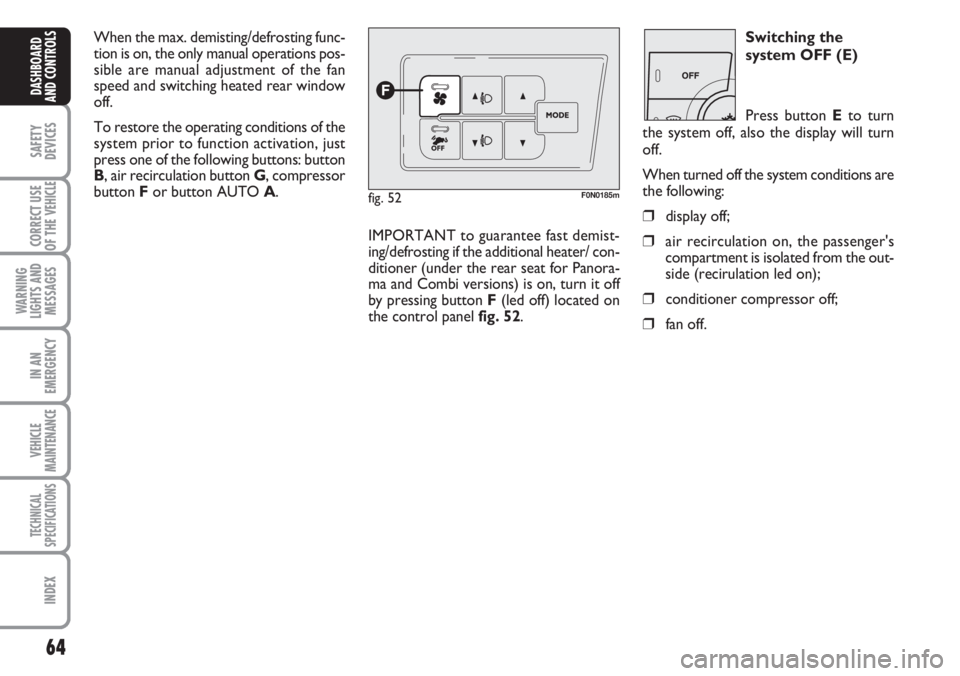
IMPORTANT to guarantee fast demist-
ing/defrosting if the additional heater/ con-
ditioner (under the rear seat for Panora-
ma and Combi versions) is on, turn it off
by pressing button F(led off) located on
the control panel fig. 52.