In ani emergency FIAT DUCATO 2008 3.G Owners Manual
[x] Cancel search | Manufacturer: FIAT, Model Year: 2008, Model line: DUCATO, Model: FIAT DUCATO 2008 3.GPages: 282, PDF Size: 4.55 MB
Page 9 of 282
8
SAFETY
DEVICES
CORRECT USE
OF THE
VEHICLE
WARNING
LIGHTS AND
MESSAGES
IN AN
EMERGENCY
VEHICLE
MAINTENANCE
TECHNICAL
SPECIFICATIONS
INDEX
DASHBOARD
AND CONTROLS
Warning light Ycoming on when driving
❒If the warning light Yturns on, this
means that the system is running a self-
test (for example for a voltage drop).
❒If the warning light Ystays on, con-
tact a Fiat Dealership.
The electronic components
inside the key may be dam-
aged if the key is submitted to
sharp knocks.
OPERATION
Each time the vehicle is started turning the
ignition key to MAR, the Fiat CODE sys-
tem control unit sends a recognition code
to the engine control unit to deactivate
the inhibitor.
The code is sent only if the Fiat CODE
system control unit has recognised the
code transmitted from the key.
Each time the ignition key is turned to
STOP, the Fiat CODE system deactivates
the functions of the engine electronic con-
trol unit.
If the code has not been recognised cor-
rectly, the warning light
Yturns on ac-
companied by the related message on the
display (see section “Warning lights and
messages”).
In this case, the key should be moved to
the STOPposition and then back to
MAR; if the lock continues, possibly try
again with the other key provided with the
vehicle. If it is still not possible to start the
vehicle, contact Fiat Dealership.
IMPORTANT Every key has its own code,
which must be memorised by the system
control unit. To memorise new keys, up
to a maximum of eight, apply to Fiat Deal-
ership.
THE KEYS
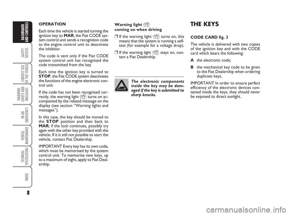
CODE CARD fig. 3
The vehicle is delivered with two copies
of the ignition key and with the CODE
card which bears the following:
Athe electronic code;
Bthe mechanical key code to be given
to the Fiat Dealership when ordering
duplicate keys.
IMPORTANT In order to ensure perfect
efficiency of the electronic devices con-
tained inside the keys, they should never
be exposed to direct sunlight.
Page 33 of 282
32
SAFETY
DEVICES
CORRECT USE
OF THE
VEHICLE
WARNING
LIGHTS AND
MESSAGES
IN AN
EMERGENCY
VEHICLE
MAINTENANCE
TECHNICAL
SPECIFICATIONS
INDEX
DASHBOARD
AND CONTROLS
Selecting the language (Language)
Display messages can be shown (after set-
ting) in different languages: Italian, German,
English, Spanish, French, Portuguese and
Dutch.
To set the required language proceed as
follows:
– briefly press button MODE: the previ-
ously set “language” will flash on the dis-
play;
– press button ▲or ▼for setting;
– briefly press button MODEto go back
to the menu screen or press the button
for long to go back to the standard screen
without storing settings.Adjusting the failure/warning
buzzer volume
(Buzzer Volume)
With this function the volume of the
buzzer accompanying any failure/warning
indication can be adjusted according to 8
levels.
To adjust the volume proceed as follows:
– briefly press button MODE: the previ-
ously set volume “level” will flash on the
display;
– press button ▲or ▼for setting;
– briefly press button MODEto go back
to the menu screen or press the button
for long to go back to the standard screen
without storing settings. If the distance unit set is “km” the fuel con-
sumption unit will be displayed in km/l or
l/100km.
If the distance unit set is “mi” the fuel con-
sumption unit will be displayed in “mpg”.
– press button ▲or ▼for setting;
– if selecting “Temperature”: briefly press but-
ton MODE, the display will show “°C” or
“°F” (according to previous setting);
– press button ▲or ▼for setting;
After setting, briefly press button MODE
to go back to the submenu screen or
press the button for long to go back to the
main menu screen without storing set-
tings.
– press again button MODEfor long to
go back to the standard screen or to the
main menu according to the current menu
level.
Page 39 of 282
38
SAFETY
DEVICES
CORRECT USE
OF THE
VEHICLE
WARNING
LIGHTS AND
MESSAGES
IN AN
EMERGENCY
VEHICLE
MAINTENANCE
TECHNICAL
SPECIFICATIONS
INDEX
DASHBOARD
AND CONTROLS
fig. 24F0N0147m
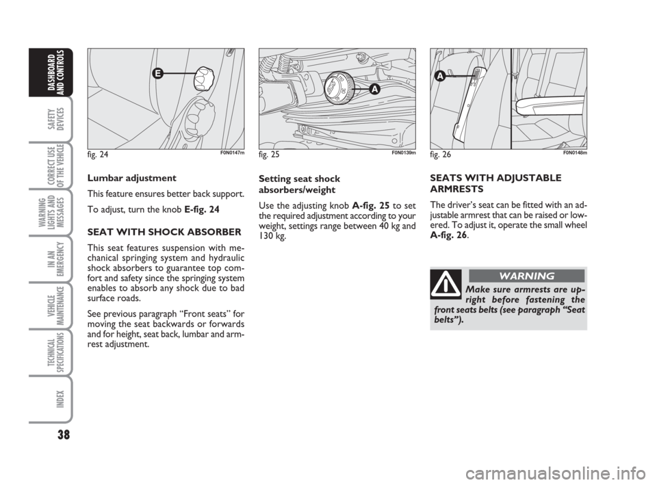
Lumbar adjustment
This feature ensures better back support.
To adjust, turn the knob E-fig. 24
SEAT WITH SHOCK ABSORBER
This seat features suspension with me-
chanical springing system and hydraulic
shock absorbers to guarantee top com-
fort and safety since the springing system
enables to absorb any shock due to bad
surface roads.
See previous paragraph “Front seats” for
moving the seat backwards or forwards
and for height, seat back, lumbar and arm-
rest adjustment.
fig. 25F0N0139m
Setting seat shock
absorbers/weight
Use the adjusting knob A-fig. 25to set
the required adjustment according to your
weight, settings range between 40 kg and
130 kg.
Make sure armrests are up-
right before fastening the
front seats belts (see paragraph “Seat
belts”). SEATS WITH ADJUSTABLE
ARMRESTS
The driver’s seat can be fitted with an ad-
justable armrest that can be raised or low-
ered. To adjust it, operate the small wheel
A-fig. 26.
fig. 26F0N0148m
WARNING
Page 84 of 282
83
SAFETY
DEVICES
CORRECT USE
OF THE
VEHICLE
WARNING
LIGHTS AND
MESSAGES
IN AN
EMERGENCY
VEHICLE
MAINTENANCE
TECHNICAL
SPECIFICATIONS
INDEX
DASHBOARD
AND CONTROLS
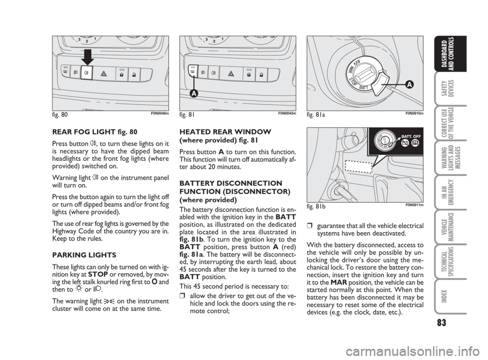
REAR FOG LIGHT fig. 80
Press button 4, to turn these lights on it
is necessary to have the dipped beam
headlights or the front fog lights (where
provided) switched on.
Warning light 4on the instrument panel
will turn on.
Press the button again to turn the light off
or turn off dipped beams and/or front fog
lights (where provided).
The use of rear fog lights is governed by the
Highway Code of the country you are in.
Keep to the rules.
PARKING LIGHTS
These lights can only be turned on with ig-
nition key at STOP or removed, by mov-
ing the left stalk knurled ring first to Oand
then to
6or 2.
The warning light
3on the instrument
cluster will come on at the same time.HEATED REAR WINDOW
(where provided) fig. 81
Press button Ato turn on this function.
This function will turn off automatically af-
ter about 20 minutes.
BATTERY DISCONNECTION
FUNCTION (DISCONNECTOR)
(where provided)
The battery disconnection function is en-
abled with the ignition key in the BATT
position, as illustrated on the dedicated
plate located in the area illustrated in
fig. 81b. To turn the ignition key to the
BATTposition, press button A(red)
fig. 81a. The battery will be disconnect-
ed, by interrupting the earth lead, about
45 seconds after the key is turned to the
BATTposition.
This 45 second period is necessary to:❒allow the driver to get out of the ve-
hicle and lock the doors using the re-
mote control;
fig. 80F0N0046mfig. 81F0N0043mfig. 81aF0N0810m
fig. 81bF0N0811m
❒guarantee that all the vehicle electrical
systems have been deactivated.
With the battery disconnected, access to
the vehicle will only be possible by un-
locking the driver’s door using the me-
chanical lock. To restore the battery con-
nection, insert the ignition key and turn
it to the MARposition, the vehicle can be
started normally at this point. When the
battery has been disconnected it may be
necessary to reset some of the electrical
devices (e.g. the clock, date, etc.).
Page 91 of 282
90
SAFETY
DEVICES
CORRECT USE
OF THE
VEHICLE
WARNING
LIGHTS AND
MESSAGES
IN AN
EMERGENCY
VEHICLE
MAINTENANCE
TECHNICAL
SPECIFICATIONS
INDEX
DASHBOARD
AND CONTROLS
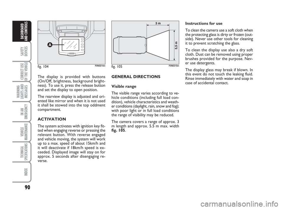
The display is provided with buttons
(On/Off, brightness, background bright-
ness). To use it, press the release button
and set the display to open position.
The rearview display is adjusted and ori-
ented like mirror and when it is not used
it shall be stowed into the top oddment
compartment.
ACTIVATION
The system activates with ignition key fit-
ted when engaging reverse or pressing the
relevant button. With reverse engaged
and vehicle moving, the system will work
up to a max. speed of about 15km/h and
it will deactivate if 18km/h speed is ex-
ceeded. Displayed image will stay on for
approx. 5 seconds after disengaging re-
verse. GENERAL DIRECTIONS
Visible range
The visible range varies according to ve-
hicle conditions (including full load con-
dition), vehicle characteristics and weath-
er conditions (daylight, rain, snow and fog);
with poor light or in full load conditions
the range of visibility may be reduced.
The camera covers a range of approx. 3
m length and approx. 5.5 m max. width
fig. 105.Instructions for use
To clean the camera use a soft cloth when
the protecting glass is dirty or frozen (out-
side). Never use other tools for cleaning
it to prevent scratching the glass.
To clean the display use also a dry soft
cloth. Dust can be removed using proper
brushes provided for the purpose. Nev-
er use detergents.
The display glass may break if blown. In
this event do not touch the leaking fluid.
Rinse immediately with water and soap in
case of accidental contact.
fig. 104F0N0214mfig. 105F0N0215m
Page 93 of 282
92
SAFETY
DEVICES
CORRECT USE
OF THE
VEHICLE
WARNING
LIGHTS AND
MESSAGES
IN AN
EMERGENCY
VEHICLE
MAINTENANCE
TECHNICAL
SPECIFICATIONS
INDEX
DASHBOARD
AND CONTROLS
IMPORTANT
Do not use abrasive detergents or sol-
vents to clean the device. To clean its ex-
ternal surface, use a wet cloth or special
products for cleaning synthetic materials.
The multimeter is installed and sealed with
lead by authorised personnel: access to
the device and relevant power and record-
ing cables is forbidden.
The vehicle owner is responsible for gov-
erning the instrument use. The inspection
must be carried out at least every two
years and will include a test to confirm
correct operation.
After the inspection, check that the plate
is updated with specified data.SPEED BLOCK
(where provided)
The vehicle is available with a speed re-
striction function that can be set, by the
user, at one of 4 pre-set levels: 90, 100,
110, 130 km/h. To activate/deactivate this
function, go to a Fiat Dealership. After the
operation a label will be stuck on the
windscreen containing the maximum set
speed.
WARNING The speedometer may show
a top speed that is higher than the actual
one set by the Dealership as provided for
by legislation.
DOORS
CENTRAL DOOR
LOCKING/UNLOCKING SYSTEM
Locking from the outside
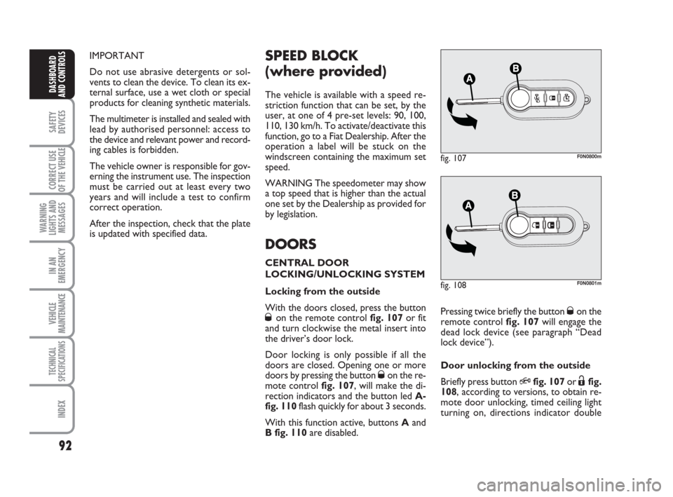
With the doors closed, press the button
Øon the remote control fig. 107or fit
and turn clockwise the metal insert into
the driver’s door lock.
Door locking is only possible if all the
doors are closed. Opening one or more
doors by pressing the button
Øon the re-
mote control fig. 107, will make the di-
rection indicators and the button led A-
fig. 110flash quickly for about 3 seconds.
With this function active, buttons Aand
B fig. 110are disabled.
fig. 107F0N0800m
Pressing twice briefly the button Øon the
remote control fig. 107will engage the
dead lock device (see paragraph “Dead
lock device”).
Door unlocking from the outside
Briefly press button
Qfig. 107or Ëfig.
108, according to versions, to obtain re-
mote door unlocking, timed ceiling light
turning on, directions indicator double
fig. 108F0N0801m
Page 94 of 282
93
SAFETY
DEVICES
CORRECT USE
OF THE
VEHICLE
WARNING
LIGHTS AND
MESSAGES
IN AN
EMERGENCY
VEHICLE
MAINTENANCE
TECHNICAL
SPECIFICATIONS
INDEX
DASHBOARD
AND CONTROLS
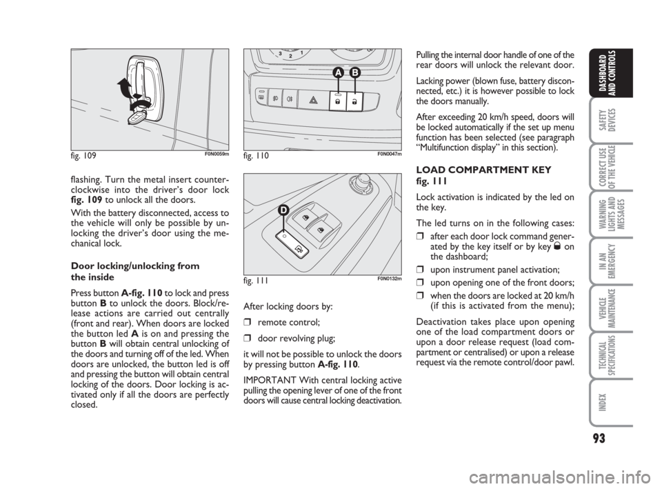
flashing. Turn the metal insert counter-
clockwise into the driver’s door lock
fig. 109to unlock all the doors.
With the battery disconnected, access to
the vehicle will only be possible by un-
locking the driver’s door using the me-
chanical lock.
Door locking/unlocking from
the inside
Press button A-fig. 110to lock and press
button Bto unlock the doors. Block/re-
lease actions are carried out centrally
(front and rear). When doors are locked
the button led Ais on and pressing the
button Bwill obtain central unlocking of
the doors and turning off of the led. When
doors are unlocked, the button led is off
and pressing the button will obtain central
locking of the doors. Door locking is ac-
tivated only if all the doors are perfectly
closed.
fig. 109F0N0059mfig. 110F0N0047m
fig. 111F0N0132m
Pulling the internal door handle of one of the
rear doors will unlock the relevant door.
Lacking power (blown fuse, battery discon-
nected, etc.) it is however possible to lock
the doors manually.
After exceeding 20 km/h speed, doors will
be locked automatically if the set up menu
function has been selected (see paragraph
“Multifunction display” in this section).
LOAD COMPARTMENT KEY
fig. 111
Lock activation is indicated by the led on
the key.
The led turns on in the following cases:
❒after each door lock command gener-
ated by the key itself or by key Øon
the dashboard;
❒upon instrument panel activation;
❒upon opening one of the front doors;
❒when the doors are locked at 20 km/h
(if this is activated from the menu);
Deactivation takes place upon opening
one of the load compartment doors or
upon a door release request (load com-
partment or centralised) or upon a release
request via the remote control/door pawl. After locking doors by:
❒remote control;
❒door revolving plug;
it will not be possible to unlock the doors
by pressing button
A-fig. 110.
IMPORTANT With central locking active
pulling the opening lever of one of the front
doors will cause central locking deactivation.
Page 99 of 282
98
SAFETY
DEVICES
CORRECT USE
OF THE
VEHICLE
WARNING
LIGHTS AND
MESSAGES
IN AN
EMERGENCY
VEHICLE
MAINTENANCE
TECHNICAL
SPECIFICATIONS
INDEX
DASHBOARD
AND CONTROLS
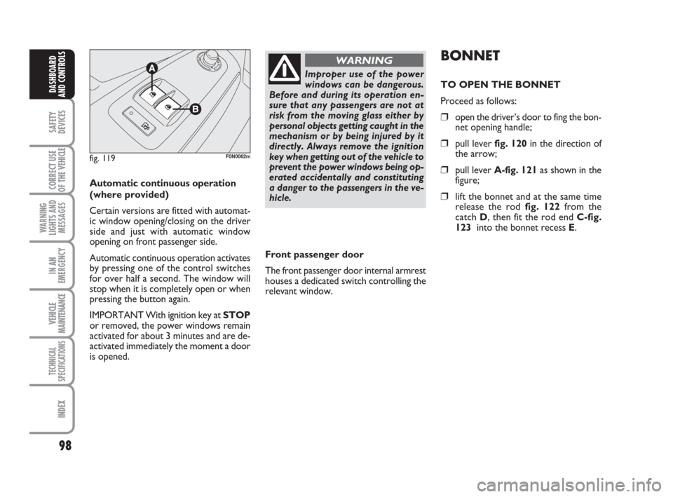
Automatic continuous operation
(where provided)
Certain versions are fitted with automat-
ic window opening/closing on the driver
side and just with automatic window
opening on front passenger side.
Automatic continuous operation activates
by pressing one of the control switches
for over half a second. The window will
stop when it is completely open or when
pressing the button again.
IMPORTANT With ignition key at STOP
or removed, the power windows remain
activated for about 3 minutes and are de-
activated immediately the moment a door
is opened.
fig. 119F0N0062m
Improper use of the power
windows can be dangerous.
Before and during its operation en-
sure that any passengers are not at
risk from the moving glass either by
personal objects getting caught in the
mechanism or by being injured by it
directly. Always remove the ignition
key when getting out of the vehicle to
prevent the power windows being op-
erated accidentally and constituting
a danger to the passengers in the ve-
hicle.
WARNINGBONNET
TO OPEN THE BONNET
Proceed as follows:
❒open the driver’s door to fing the bon-
net opening handle;
❒pull lever fig. 120in the direction of
the arrow;
❒pull lever A-fig. 121as shown in the
figure;
❒lift the bonnet and at the same time
release the rod fig. 122 from the
catch D, then fit the rod end C-fig.
123 into the bonnet recess E.
Front passenger door
The front passenger door internal armrest
houses a dedicated switch controlling the
relevant window.
Page 106 of 282
105
SAFETY
DEVICES
CORRECT USE
OF THE
VEHICLE
WARNING
LIGHTS AND
MESSAGES
IN AN
EMERGENCY
VEHICLE
MAINTENANCE
TECHNICAL
SPECIFICATIONS
INDEX
DASHBOARD
AND CONTROLS
MSR system
(engine braking torque control)
It is an integral part of the ASR system that
in case of sudden gear shifting, cuts in pro-
viding torque to the engine thus prevent-
ing excessive driving wheel drive that, spe-
cially in poor grip conditions, can lead to
loss of stability.
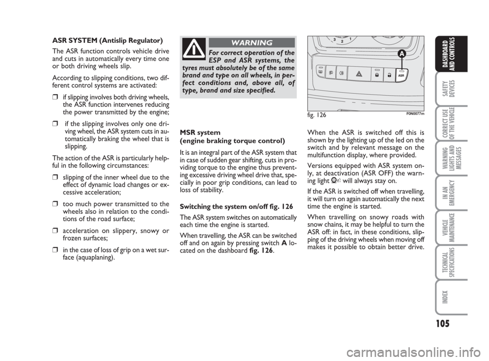
Switching the systemon/off fig. 126
The ASR system switches on automatically
each time the engine is started.
When travelling, the ASR can be switched
off and on again by pressing switch Alo-
cated on the dashboard fig. 126. When the ASR is switched off this is
shown by the lighting up of the led on the
switch and by relevant message on the
multifunction display, where provided.
Versions equipped with ASR system on-
ly, at deactivation (ASR OFF) the warn-
ing light Vwill always stay on.
If the ASR is switched off when travelling,
it will turn on again automatically the next
time the engine is started.
When travelling on snowy roads with
snow chains, it may be helpful to turn the
ASR off: in fact, in these conditions, slip-
ping of the driving wheels when moving off
makes it possible to obtain better drive.
For correct operation of the
ESP and ASR systems, the
tyres must absolutely be of the same
brand and type on all wheels, in per-
fect conditions and, above all, of
type, brand and size specified.
WARNING
fig. 126F0N0077m
ASR SYSTEM (Antislip Regulator)
The ASR function controls vehicle drive
and cuts in automatically every time one
or both driving wheels slip.
According to slipping conditions, two dif-
ferent control systems are activated:
❒if slipping involves both driving wheels,
the ASR function intervenes reducing
the power transmitted by the engine;
❒if the slipping involves only one dri-
ving wheel, the ASR system cuts in au-
tomatically braking the wheel that is
slipping.
The action of the ASR is particularly help-
ful in the following circumstances:
❒slipping of the inner wheel due to the
effect of dynamic load changes or ex-
cessive acceleration;
❒too much power transmitted to the
wheels also in relation to the condi-
tions of the road surface;
❒acceleration on slippery, snowy or
frozen surfaces;
❒in the case of loss of grip on a wet sur-
face (aquaplaning).
Page 108 of 282
107
SAFETY
DEVICES
CORRECT USE
OF THE
VEHICLE
WARNING
LIGHTS AND
MESSAGES
IN AN
EMERGENCY
VEHICLE
MAINTENANCE
TECHNICAL
SPECIFICATIONS
INDEX
DASHBOARD
AND CONTROLS
PARKING SENSORS
(where provided)
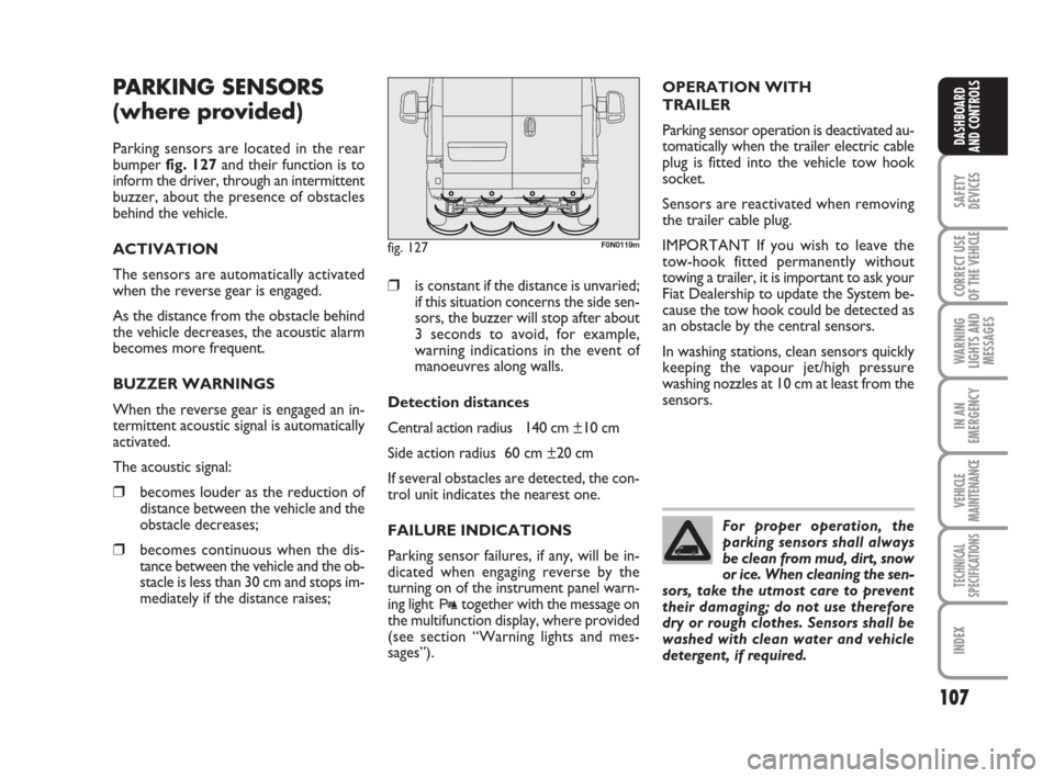
Parking sensors are located in the rear
bumper fig. 127and their function is to
inform the driver, through an intermittent
buzzer, about the presence of obstacles
behind the vehicle.
ACTIVATION
The sensors are automatically activated
when the reverse gear is engaged.
As the distance from the obstacle behind
the vehicle decreases, the acoustic alarm
becomes more frequent.
BUZZER WARNINGS
When the reverse gear is engaged an in-
termittent acoustic signal is automatically
activated.
The acoustic signal:
❒becomes louder as the reduction of
distance between the vehicle and the
obstacle decreases;
❒becomes continuous when the dis-
tance between the vehicle and the ob-
stacle is less than 30 cm and stops im-
mediately if the distance raises;
❒is constant if the distance is unvaried;
if this situation concerns the side sen-
sors, the buzzer will stop after about
3 seconds to avoid, for example,
warning indications in the event of
manoeuvres along walls.
Detection distances
Central action radius 140 cm ±10 cm
Side action radius 60 cm ±20 cm
If several obstacles are detected, the con-
trol unit indicates the nearest one.
FAILURE INDICATIONS
Parking sensor failures, if any, will be in-
dicated when engaging reverse by the
turning on of the instrument panel warn-
ing light
ttogether with the message on
the multifunction display, where provided
(see section “Warning lights and mes-
sages”).
fig. 127F0N0119m
For proper operation, the
parking sensors shall always
be clean from mud, dirt, snow
or ice. When cleaning the sen-
sors, take the utmost care to prevent
their damaging; do not use therefore
dry or rough clothes. Sensors shall be
washed with clean water and vehicle
detergent, if required.
OPERATION WITH
TRAILER
Parking sensor operation is deactivated au-
tomatically when the trailer electric cable
plug is fitted into the vehicle tow hook
socket.
Sensors are reactivated when removing
the trailer cable plug.
IMPORTANT If you wish to leave the
tow-hook fitted permanently without
towing a trailer, it is important to ask your
Fiat Dealership to update the System be-
cause the tow hook could be detected as
an obstacle by the central sensors.
In washing stations, clean sensors quickly
keeping the vapour jet/high pressure
washing nozzles at 10 cm at least from the
sensors.