seat adjustment FIAT DUCATO 2009 3.G Owners Manual
[x] Cancel search | Manufacturer: FIAT, Model Year: 2009, Model line: DUCATO, Model: FIAT DUCATO 2009 3.GPages: 282, PDF Size: 4.55 MB
Page 38 of 282
37
SAFETY
DEVICES
CORRECT USE
OF THE
VEHICLE
WARNING
LIGHTS AND
MESSAGES
IN AN
EMERGENCY
VEHICLE
MAINTENANCE
TECHNICAL
SPECIFICATIONS
INDEX
DASHBOARD
AND CONTROLS
Fabric upholstery of your Fiat
Ducato is purpose-made to
withstand common wear re-
sulting from normal use of the
vehicle. It is however absolutely neces-
sary to prevent hard and/or prolonged
scratching/scraping caused by clothing
accessories like metallic buckles, studs,
“Velcro” fixings, etc. that stressing lo-
cally the fabric could break yarns and
damage the upholstery as a conse-
quence.
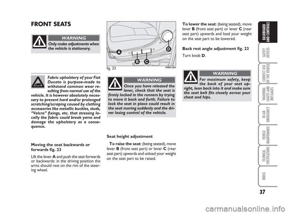
Seat height adjustment
To raise the seat: (being seated), move
lever B (front seat part) or lever C (rear
seat part) upwards and unload your weight
on the seat part to be raised.
FRONT SEATS
fig. 23F0N0118m
Only make adjustments when
the vehicle is stationary.
WARNING
Moving the seat backwards or
forwards fig. 23
Lift the lever Aand push the seat forwards
or backwards: in the driving position the
arms should rest on the rim of the steer-
ing wheel.
Once you have released the
lever, check that the seat is
firmly locked in the runners by trying
to move it back and forth. Failure to
lock the seat in place could result in
the seat moving suddenly and the dri-
ver losing control of the vehicle.
WARNINGFor maximum safety, keep
the back of your seat up-
right, lean back into it and make sure
the seat belt fits closely across your
chest and hips.
WARNING
To lower the seat: (being seated), move
lever B(front seat part) or lever C(rear
seat part) upwards and load your weight
on the seat part to be lowered.
Back rest angle adjustment fig. 23
Turn knob D.
Page 39 of 282
38
SAFETY
DEVICES
CORRECT USE
OF THE
VEHICLE
WARNING
LIGHTS AND
MESSAGES
IN AN
EMERGENCY
VEHICLE
MAINTENANCE
TECHNICAL
SPECIFICATIONS
INDEX
DASHBOARD
AND CONTROLS
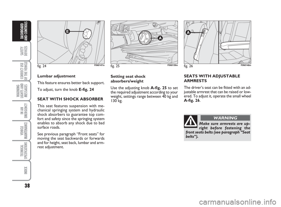
fig. 24F0N0147m
Lumbar adjustment
This feature ensures better back support.
To adjust, turn the knob E-fig. 24
SEAT WITH SHOCK ABSORBER
This seat features suspension with me-
chanical springing system and hydraulic
shock absorbers to guarantee top com-
fort and safety since the springing system
enables to absorb any shock due to bad
surface roads.
See previous paragraph “Front seats” for
moving the seat backwards or forwards
and for height, seat back, lumbar and arm-
rest adjustment.
fig. 25F0N0139m
Setting seat shock
absorbers/weight
Use the adjusting knob A-fig. 25to set
the required adjustment according to your
weight, settings range between 40 kg and
130 kg.
Make sure armrests are up-
right before fastening the
front seats belts (see paragraph “Seat
belts”). SEATS WITH ADJUSTABLE
ARMRESTS
The driver’s seat can be fitted with an ad-
justable armrest that can be raised or low-
ered. To adjust it, operate the small wheel
A-fig. 26.
fig. 26F0N0148m
WARNING
Page 40 of 282
39
SAFETY
DEVICES
CORRECT USE
OF THE
VEHICLE
WARNING
LIGHTS AND
MESSAGES
IN AN
EMERGENCY
VEHICLE
MAINTENANCE
TECHNICAL
SPECIFICATIONS
INDEX
DASHBOARD
AND CONTROLS
Only make adjustments
when the vehicle is station-
ary. Specially when revolving the seat,
make sure it is not interfering with the
handbrake lever.
Make sure the outer armrest
(door side) is completely up-
right before unfastening the seat belts
and getting out of the vehicle.
WARNING
Should it be absolutely nec-
essary to carry a child seat
on the front passenger’s seat, make
sure to deactivate the front passen-
ger’s air bag, to fasten the passenger’s
seat belt and to lower completely the
armrests to prevent their accidental
moving.
WARNING
REVOLVING SEAT WITH
INTEGRAL SEAT
BELT (where provided)
The seat is fitted with seat belts with three
anchorage points fig. 28, two adjustable
arm-rests (for adjustment see paragraph
“Seats with adjustable armrests”) and a
height-adjustable head restraint (see “Head
restraint” paragraph for adjustment).
WARNING
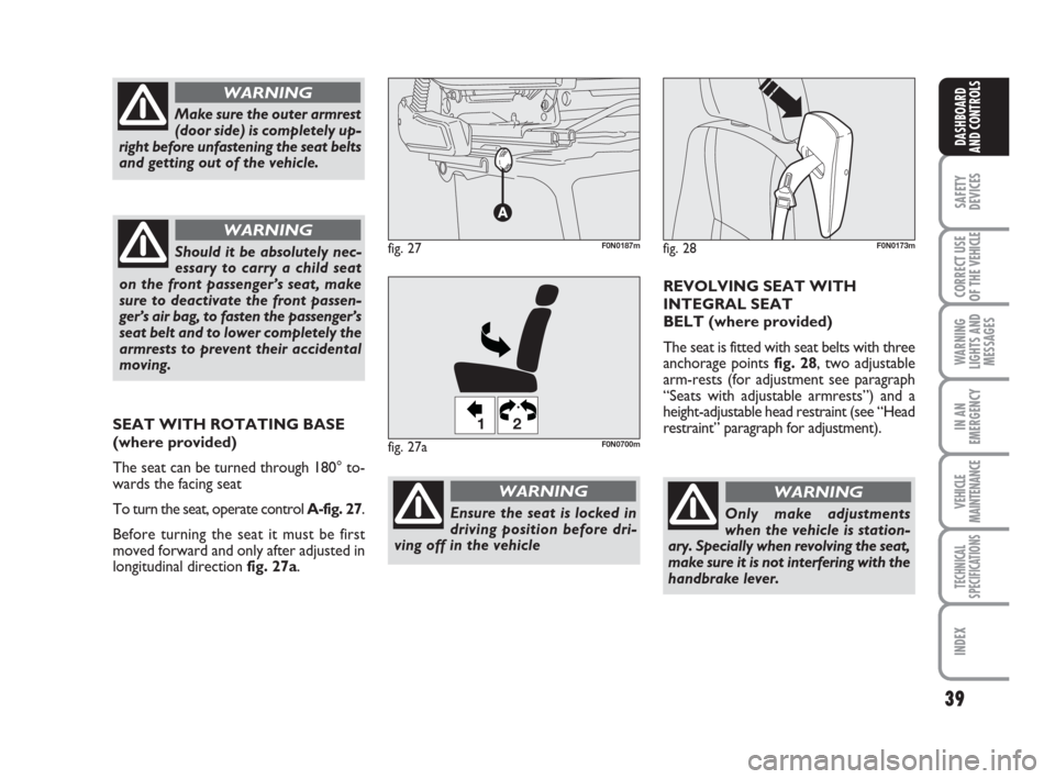
fig. 28F0N0173mfig. 27F0N0187m
Ensure the seat is locked in
driving position before dri-
ving off in the vehicle
WARNING
SEAT WITH ROTATING BASE
(where provided)
The seat can be turned through 180° to-
wards the facing seat
To turn the seat, operate control A-fig. 27.
Before turning the seat it must be first
moved forward and only after adjusted in
longitudinal direction fig. 27a.
fig. 27a
12
F0N0700m
Page 41 of 282
40
SAFETY
DEVICES
CORRECT USE
OF THE
VEHICLE
WARNING
LIGHTS AND
MESSAGES
IN AN
EMERGENCY
VEHICLE
MAINTENANCE
TECHNICAL
SPECIFICATIONS
INDEX
DASHBOARD
AND CONTROLS
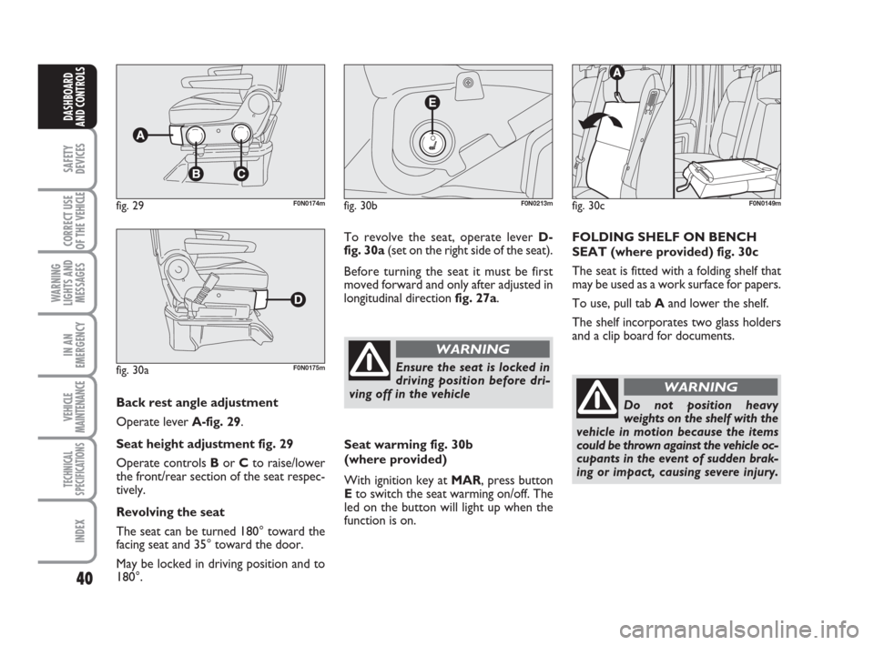
Back rest angle adjustment
Operate lever A-fig. 29.
Seat height adjustment fig. 29
Operate controls Bor Cto raise/lower
the front/rear section of the seat respec-
tively.
Revolving the seat
The seat can be turned 180° toward the
facing seat and 35° toward the door.
May be locked in driving position and to
180°.
fig. 29F0N0174m
fig. 30aF0N0175m
To revolve the seat, operate lever D-
fig. 30a(set on the right side of the seat).
Before turning the seat it must be first
moved forward and only after adjusted in
longitudinal direction fig. 27a.
fig. 30bF0N0213m
Ensure the seat is locked in
driving position before dri-
ving off in the vehicle
WARNING
Seat warming fig. 30b
(where provided)
With ignition key at MAR, press button
Eto switch the seat warming on/off. The
led on the button will light up when the
function is on.
fig. 30cF0N0149m
FOLDING SHELF ON BENCH
SEAT (where provided) fig. 30c
The seat is fitted with a folding shelf that
may be used as a work surface for papers.
To use, pull tab Aand lower the shelf.
The shelf incorporates two glass holders
and a clip board for documents.
Do not position heavy
weights on the shelf with the
vehicle in motion because the items
could be thrown against the vehicle oc-
cupants in the event of sudden brak-
ing or impact, causing severe injury.
WARNING
Page 42 of 282
41
SAFETY
DEVICES
CORRECT USE
OF THE
VEHICLE
WARNING
LIGHTS AND
MESSAGES
IN AN
EMERGENCY
VEHICLE
MAINTENANCE
TECHNICAL
SPECIFICATIONS
INDEX
DASHBOARD
AND CONTROLS
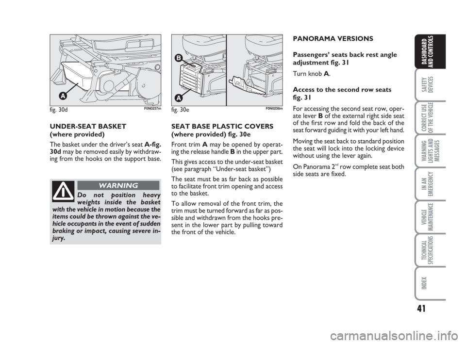
fig. 30dF0N0237mfig. 30eF0N0238m
UNDER-SEAT BASKET
(where provided)
The basket under the driver’s seat A-fig.
30dmay be removed easily by withdraw-
ing from the hooks on the support base.
Do not position heavy
weights inside the basket
with the vehicle in motion because the
items could be thrown against the ve-
hicle occupants in the event of sudden
braking or impact, causing severe in-
jury.
WARNING
SEAT BASE PLASTIC COVERS
(where provided) fig. 30e
Front trim Amay be opened by operat-
ing the release handle Bin the upper part.
This gives access to the under-seat basket
(see paragraph “Under-seat basket”)
The seat must be as far back as possible
to facilitate front trim opening and access
to the basket.
To allow removal of the front trim, the
trim must be turned forward as far as pos-
sible and withdrawn from the hooks pre-
sent in the lower part by pulling toward
the front of the vehicle.PANORAMA VERSIONS
Passengers’ seats back rest angle
adjustment fig. 31
Turn knob A.
Access to the second row seats
fig. 31
For accessing the second seat row, oper-
ate lever Bof the external right side seat
of the first row and fold the back of the
seat forward guiding it with your left hand.
Moving the seat back to standard position
the seat will lock into the locking device
without using the lever again.
On Panorama 2
ndrow complete seat both
side seats are fixed.
Page 43 of 282
42
SAFETY
DEVICES
CORRECT USE
OF THE
VEHICLE
WARNING
LIGHTS AND
MESSAGES
IN AN
EMERGENCY
VEHICLE
MAINTENANCE
TECHNICAL
SPECIFICATIONS
INDEX
DASHBOARD
AND CONTROLS
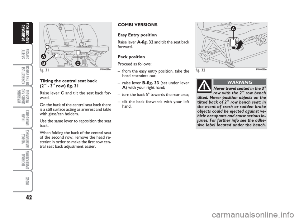
fig. 31F0N0227mfig. 32F0N0228m
Tilting the central seat back
(2nd- 3rdrow) fig. 31
Raise lever Cand tilt the seat back for-
ward.
On the back of the central seat back there
is a stiff surface acting as armrest and table
with glass/can holders.
Use the same lever to reposition the seat
back.
When folding the back of the central seat
of the second row, remove the head re-
straint in order to make the first row cen-
tral seat back adjustment easier.COMBI VERSIONS
Easy Entry position
Raise lever A-fig. 32and tilt the seat back
forward.
Pack position
Proceed as follows:
– from the easy entry position, take the
head restraints out;
– raise lever B-fig. 33(set under lever
A) with your right hand;
– turn the back 5° towards the rear area;
– tilt the back forwards with your left
hand.Never travel seated in the 3rd
row with the 2ndrow bench
tilted. Never position objects on the
tilted back of 2
ndrow bench seat: in
the event of crash or sudden brake
objects could be ejected against ve-
hicle occupants and cause serious in-
juries. For further info see the adhe-
sive label located under the bench.
WARNING
Page 45 of 282
44
SAFETY
DEVICES
CORRECT USE
OF THE
VEHICLE
WARNING
LIGHTS AND
MESSAGES
IN AN
EMERGENCY
VEHICLE
MAINTENANCE
TECHNICAL
SPECIFICATIONS
INDEX
DASHBOARD
AND CONTROLS
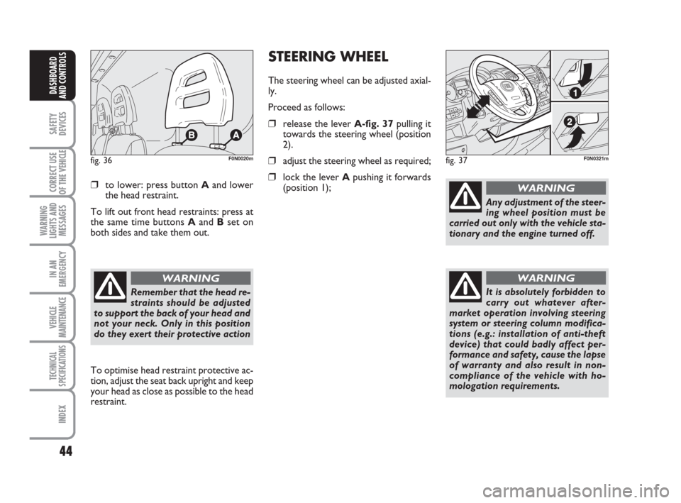
❒to lower: press button Aand lower
the head restraint.
To lift out front head restraints: press at
the same time buttons Aand Bset on
both sides and take them out.
fig. 36F0N0020m
To optimise head restraint protective ac-
tion, adjust the seat back upright and keep
your head as close as possible to the head
restraint.
Remember that the head re-
straints should be adjusted
to support the back of your head and
not your neck. Only in this position
do they exert their protective action
WARNING
STEERING WHEEL
The steering wheel can be adjusted axial-
ly.
Proceed as follows:
❒release the lever A-fig. 37pulling it
towards the steering wheel (position
2).
❒adjust the steering wheel as required;
❒lock the lever Apushing it forwards
(position 1);
fig. 37F0N0321m
Any adjustment of the steer-
ing wheel position must be
carried out only with the vehicle sta-
tionary and the engine turned off.
WARNING
It is absolutely forbidden to
carry out whatever after-
market operation involving steering
system or steering column modifica-
tions (e.g.: installation of anti-theft
device) that could badly affect per-
formance and safety, cause the lapse
of warranty and also result in non-
compliance of the vehicle with ho-
mologation requirements.
WARNING
Page 54 of 282
53
SAFETY
DEVICES
CORRECT USE
OF THE
VEHICLE
WARNING
LIGHTS AND
MESSAGES
IN AN
EMERGENCY
VEHICLE
MAINTENANCE
TECHNICAL
SPECIFICATIONS
INDEX
DASHBOARD
AND CONTROLS
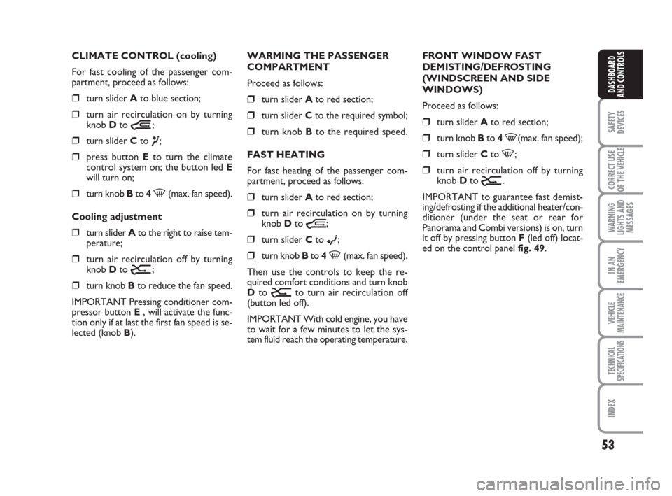
CLIMATE CONTROL (cooling)
For fast cooling of the passenger com-
partment, proceed as follows:
❒turn slider Ato blue section;
❒turn air recirculation on by turning
knob Dto
Ò;
❒turn slider Cto ¶;
❒press button Eto turn the climate
control system on; the button led E
will turn on;
❒turn knob Bto 4-(max. fan speed).
Cooling adjustment
❒turn slider Ato the right to raise tem-
perature;
❒turn air recirculation off by turning
knob Dto
Ú;
❒turn knob Bto reduce the fan speed.
IMPORTANT Pressing conditioner com-
pressor button E, will activate the func-
tion only if at last the first fan speed is se-
lected (knob B).WARMING THE PASSENGER
COMPARTMENT
Proceed as follows:
❒turn slider Ato red section;
❒turn slider Cto the required symbol;
❒turn knob Bto the required speed.
FAST HEATING
For fast heating of the passenger com-
partment, proceed as follows:
❒turn slider Ato red section;
❒turn air recirculation on by turning
knob Dto
Ò;
❒turn slider Cto ©;
❒turn knob Bto 4-(max. fan speed).
Then use the controls to keep the re-
quired comfort conditions and turn knob
Dto
Úto turn air recirculation off
(button led off).
IMPORTANT With cold engine, you have
to wait for a few minutes to let the sys-
tem fluid reach the operating temperature.FRONT WINDOW FAST
DEMISTING/DEFROSTING
(WINDSCREEN AND SIDE
WINDOWS)
Proceed as follows:
❒turn slider Ato red section;
❒turn knob Bto 4-(max. fan speed);
❒turn slider Cto -;
❒turn air recirculation off by turning
knob D to
Ú.
IMPORTANT to guarantee fast demist-
ing/defrosting if the additional heater/con-
ditioner (under the seat or rear for
Panorama and Combi versions) is on, turn
it off by pressing button F(led off) locat-
ed on the control panel fig. 49.
Page 65 of 282
64
SAFETY
DEVICES
CORRECT USE
OF THE
VEHICLE
WARNING
LIGHTS AND
MESSAGES
IN AN
EMERGENCY
VEHICLE
MAINTENANCE
TECHNICAL
SPECIFICATIONS
INDEX
DASHBOARD
AND CONTROLS
When the max. demisting/defrosting func-
tion is on, the only manual operations pos-
sible are manual adjustment of the fan
speed and switching heated rear window
off.
To restore the operating conditions of the
system prior to function activation, just
press one of the following buttons: button
B, air recirculation button G, compressor
button For button AUTO A.
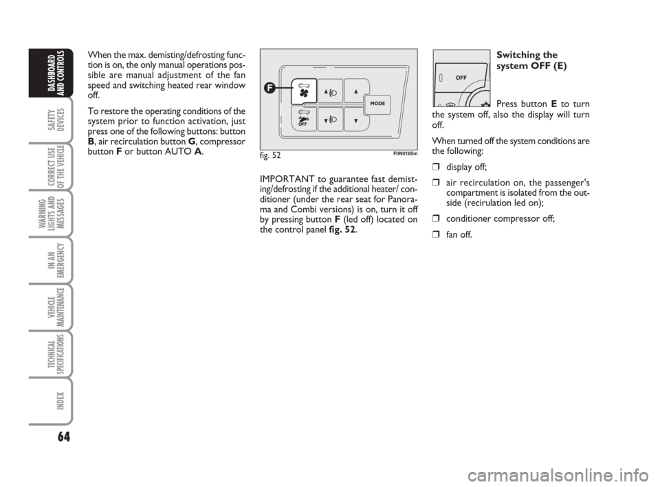
fig. 52F0N0185m
Switching the
system OFF (E)
Press button Eto turn
the system off, also the display will turn
off.
When turned off the system conditions are
the following:
❒display off;
❒air recirculation on, the passenger's
compartment is isolated from the out-
side (recirulation led on);
❒conditioner compressor off;
❒fan off.
IMPORTANT to guarantee fast demist-
ing/defrosting if the additional heater/ con-
ditioner (under the rear seat for Panora-
ma and Combi versions) is on, turn it off
by pressing button F(led off) located on
the control panel fig. 52.
Page 161 of 282
160
WARNING
LIGHTS AND
MESSAGES
VEHICLE
MAINTENANCE
TECHNICAL
SPECIFICATIONS
IINDEX
DASHBOARD
AND CONTROLS
SAFETY
DEVICES
CORRECT USE
OF THE
VEHICLE
IN AN
EMERGENCY
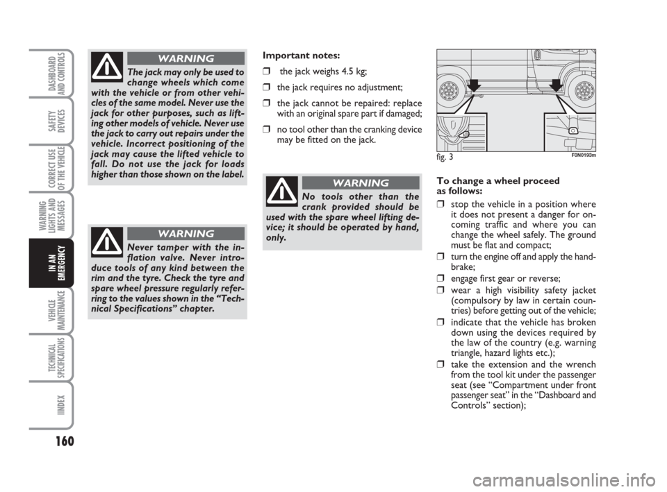
To change a wheel proceed
as follows:
❒stop the vehicle in a position where
it does not present a danger for on-
coming traffic and where you can
change the wheel safely. The ground
must be flat and compact;
❒turn the engine off and apply the hand-
brake;
❒engage first gear or reverse;
❒wear a high visibility safety jacket
(compulsory by law in certain coun-
tries) before getting out of the vehicle;
❒indicate that the vehicle has broken
down using the devices required by
the law of the country (e.g. warning
triangle, hazard lights etc.);
❒take the extension and the wrench
from the tool kit under the passenger
seat (see “Compartment under front
passenger seat” in the “Dashboard and
Controls” section);
The jack may only be used to
change wheels which come
with the vehicle or from other vehi-
cles of the same model. Never use the
jack for other purposes, such as lift-
ing other models of vehicle. Never use
the jack to carry out repairs under the
vehicle. Incorrect positioning of the
jack may cause the lifted vehicle to
fall. Do not use the jack for loads
higher than those shown on the label.
WARNING
Never tamper with the in-
flation valve. Never intro-
duce tools of any kind between the
rim and the tyre. Check the tyre and
spare wheel pressure regularly refer-
ring to the values shown in the “Tech-
nical Specifications” chapter.
WARNING
Important notes:
❒the jack weighs 4.5 kg;
❒the jack requires no adjustment;
❒the jack cannot be repaired: replace
with an original spare part if damaged;
❒no tool other than the cranking device
may be fitted on the jack.
fig. 3F0N0193m
No tools other than the
crank provided should be
used with the spare wheel lifting de-
vice; it should be operated by hand,
only.
WARNING