technical data FIAT DUCATO 2009 3.G Owners Manual
[x] Cancel search | Manufacturer: FIAT, Model Year: 2009, Model line: DUCATO, Model: FIAT DUCATO 2009 3.GPages: 282, PDF Size: 4.55 MB
Page 29 of 282
28
SAFETY
DEVICES
CORRECT USE
OF THE
VEHICLE
WARNING
LIGHTS AND
MESSAGES
IN AN
EMERGENCY
VEHICLE
MAINTENANCE
TECHNICAL
SPECIFICATIONS
INDEX
DASHBOARD
AND CONTROLS
Day
YearMonth
Deutsch
Français
English
Español
Italiano
Nederland
Português Example:
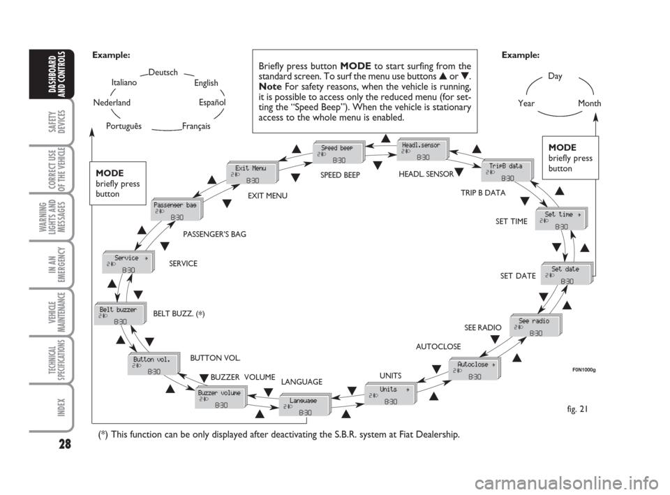
fig. 21 Example:
Briefly press button MODEto start surfing from the
standard screen. To surf the menu use buttons ▲or ▼.
NoteFor safety reasons, when the vehicle is running,
it is possible to access only the reduced menu (for set-
ting the “Speed Beep”). When the vehicle is stationary
access to the whole menu is enabled.
F0N1000g
MODE
briefly press
button
▲
▼
EXIT MENUSPEED BEEPHEADL. SENSOR
SET TIME
SET DATE
SEE RADIO
AUTOCLOSE
UNITS
LANGUAGE BUZZER VOLUME BUTTON VOL. SERVICEPASSENGER’S BAG
(*) This function can be only displayed after deactivating the S.B.R. system at Fiat Dealership.
TRIP B DATA
MODE
briefly press
button
▲
▼▲
▼▲
▼
▲
▼
▲ ▼
▲ ▼ ▲
▼
▲
▼
▲
▼
▲▼
▲▼
▲▼
▲▼▲ ▼
BELT BUZZ. (*)
Page 30 of 282
29
SAFETY
DEVICES
CORRECT USE
OF THE
VEHICLE
WARNING
LIGHTS AND
MESSAGES
IN AN
EMERGENCY
VEHICLE
MAINTENANCE
TECHNICAL
SPECIFICATIONS
INDEX
DASHBOARD
AND CONTROLS
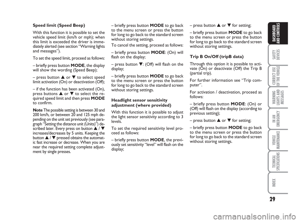
– briefly press button MODE to go back
to the menu screen or press the button
for long to go back to the standard screen
without storing settings.
To cancel the setting, proceed as follows:
– briefly press button MODE: (On) will
flash on the display;
– press button ▼: (Off) will flash on the
display;
– briefly press button MODEto go back
to the menu screen or press the button
for long to go back to the standard screen
without storing settings.
Headlight sensor sensitivity
adjustment (where provided)
With this function it is possible to adjust
the light sensor sensitivity according to 3
levels.
To set the required sensitivity level pro-
ceed as follows:
– briefly press button MODE, the previ-
ously set sensitivity “level” will flash on the
display; Speed limit (Speed Beep)
With this function it is possible to set the
vehicle speed limit (km/h or mph); when
this limit is exceeded the driver is imme-
diately alerted (see section “Warning lights
and messages”).
To set the speed limit, proceed as follows:
– briefly press button MODE, the display
will show the wording (Speed Beep);
– press button ▲or ▼to select speed
limit activation (On) or deactivation (Off);
– if the function has been activated (On),
press buttons ▲or ▼to select the re-
quired speed limit and then press MODE
to confirm.
NoteThe possible setting is between 30 and
200 km/h, or between 20 and 125 mph de-
pending on the unit set previously (see para-
graph “Setting the distance unit (Units)”) de-
scribed later. Every press on button
▲/ ▼increases/decreases by 5 units. Keeping the
button ▲/ ▼pressed obtains the automat-
ic fast increase or decrease. When you are
near the required setting complete adjust-
ment by single presses.
– press button ▲or ▼for setting;
– briefly press button MODEto go back
to the menu screen or press the button
for long to go back to the standard screen
without storing settings.
Trip B On/Off (tripB data)
Through this option it is possible to acti-
vate (On) or deactivate (Off) the Trip B
(partial trip).
For further information see “Trip com-
puter”.
For activation / deactivation, proceed as
follows:
– briefly press button MODE: (On) or
(Off) will flash on the display (according to
previous setting);
– press button ▲or ▼for setting;
– briefly press button MODEto go back
to the menu screen or press the button
for long to go back to the standard screen
without storing settings.
Page 93 of 282
92
SAFETY
DEVICES
CORRECT USE
OF THE
VEHICLE
WARNING
LIGHTS AND
MESSAGES
IN AN
EMERGENCY
VEHICLE
MAINTENANCE
TECHNICAL
SPECIFICATIONS
INDEX
DASHBOARD
AND CONTROLS
IMPORTANT
Do not use abrasive detergents or sol-
vents to clean the device. To clean its ex-
ternal surface, use a wet cloth or special
products for cleaning synthetic materials.
The multimeter is installed and sealed with
lead by authorised personnel: access to
the device and relevant power and record-
ing cables is forbidden.
The vehicle owner is responsible for gov-
erning the instrument use. The inspection
must be carried out at least every two
years and will include a test to confirm
correct operation.
After the inspection, check that the plate
is updated with specified data.SPEED BLOCK
(where provided)
The vehicle is available with a speed re-
striction function that can be set, by the
user, at one of 4 pre-set levels: 90, 100,
110, 130 km/h. To activate/deactivate this
function, go to a Fiat Dealership. After the
operation a label will be stuck on the
windscreen containing the maximum set
speed.
WARNING The speedometer may show
a top speed that is higher than the actual
one set by the Dealership as provided for
by legislation.
DOORS
CENTRAL DOOR
LOCKING/UNLOCKING SYSTEM
Locking from the outside
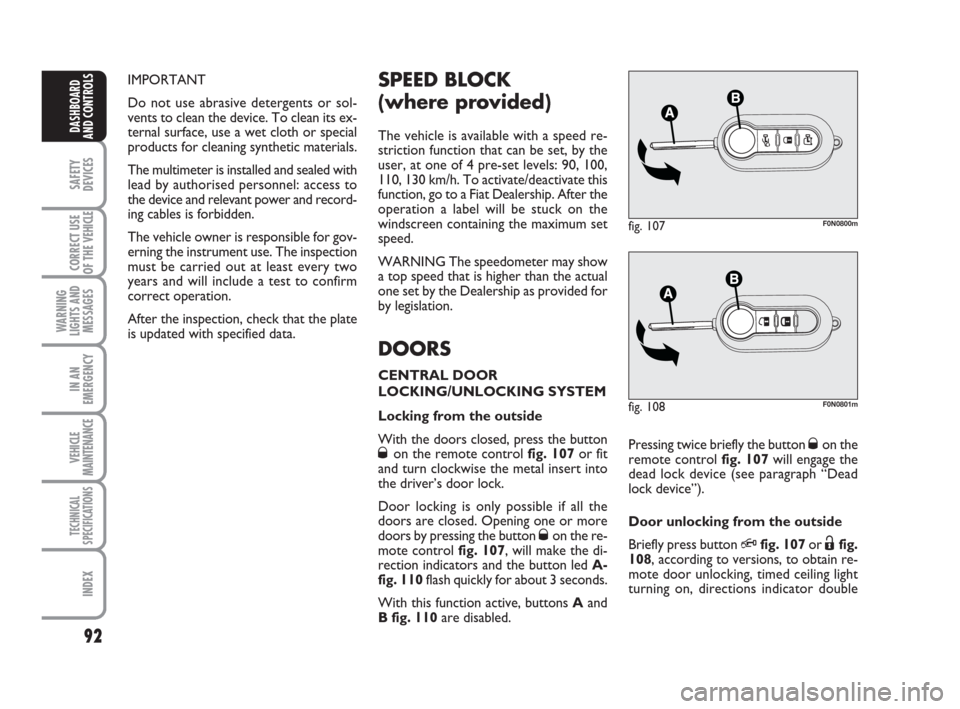
With the doors closed, press the button
Øon the remote control fig. 107or fit
and turn clockwise the metal insert into
the driver’s door lock.
Door locking is only possible if all the
doors are closed. Opening one or more
doors by pressing the button
Øon the re-
mote control fig. 107, will make the di-
rection indicators and the button led A-
fig. 110flash quickly for about 3 seconds.
With this function active, buttons Aand
B fig. 110are disabled.
fig. 107F0N0800m
Pressing twice briefly the button Øon the
remote control fig. 107will engage the
dead lock device (see paragraph “Dead
lock device”).
Door unlocking from the outside
Briefly press button
Qfig. 107or Ëfig.
108, according to versions, to obtain re-
mote door unlocking, timed ceiling light
turning on, directions indicator double
fig. 108F0N0801m
Page 113 of 282
112
SAFETY
DEVICES
CORRECT USE
OF THE
VEHICLE
WARNING
LIGHTS AND
MESSAGES
IN AN
EMERGENCY
VEHICLE
MAINTENANCE
TECHNICAL
SPECIFICATIONS
INDEX
DASHBOARD
AND CONTROLS
During normal service the
diesel particulate filter (DPF)
reaches high temperatures. Do not
therefore park the car over inflam-
mable materials (grass, dry leaves,
pine needles, etc.): fire hazard.
WARNING
PROTECTING
THE ENVIRONMENT
The devices for curtailing diesel fuel en-
gine emissions are the following:
❒oxidising catalytic converter;
❒exhaust gas recirculation system
(E.G.R.);
❒diesel particulate filter (DPF).
During normal service the
catalyst reaches high tem-
peratures. Do not therefore park the
car over inflammable materials (grass,
dry leaves, pine needles, etc.): fire
hazard.
WARNING
DIESEL PARTICULATE FILTER
(DPF)
The Diesel Particulate Filter is a mechan-
ical filter, integral with the exhaust system,
that physically traps particulates present
in the exhaust gases of Diesel engines.
The diesel particular filter has been adopt-
ed to eliminate almost totally particulates
in compliance with current / future law
regulations.
During normal use of the car, the engine
control unit records a set of data (e.g.:
travel time, type of route, temperatures,
etc.) and it will then calculate how much
particulates has been trapped by the filter.
Since this filter physically traps particulates,
it shall be cleaned (reclaimed) at regular
intervals by burning carbon particles.
Reclaiming procedure is controlled auto-
matically by the engine control unit ac-
cording to the filter conditions and the
conditions of use of the car.During reclaiming the following phenomena
could take place: idling slight increase, fan ac-
tivation, slight smoke increase, high exhaust
temperatures. These situations shall not be
considered as faults and they do not affect
car performance and environment.
If the dedicated message is displayed, refer to
section “Warning lights and messages”.
Page 120 of 282
HOW TO KEEP THE SEAT
BELTS ALWAYS IN EFFICIENT
CONDITIONS
Observe the following:
❒always use the belt with the tap taut
and never twisted; make sure that it
is free to run without impediments;
❒after a serious accident, replace the
belt being worn at that time, even if it
does not appear damaged. Always re-
place the seat belts if pretensioners
have been activated;
❒to clean the belts, wash by hand with
neutral soap, rinse and leave to dry in
the shade. Never use strong deter-
gents, bleach or dyes or other chem-
ical substance that might weaken the
fibres;
❒prevent the reels from getting wet:
their correct operation is only guar-
anteed if water does not get inside;
❒replace the seat belt when showing
significant wear or cut signs.For optimal protection in the event of a
crash, all passengers must be seated and
wearing adequate restraint systems.
This is even more important for children.
This prescription is compulsory in all EC
countries according to EC Directive
2003/20/EC.
Compared with adults, their head is pro-
portionally larger and heavier than the rest
of the body, while the muscles and bone
structure are not completely developed.
Therefore, correct restraint systems are
necessary, other than adult seat belts. The
results of research on the best child re-
straint systems are contained in the Euro-
pean Standard EEC-R44. This Standard en-
forces the use of restraint systems classi-
fied in five groups:Group 0 0-10 kg in weight
Group 0+ 0-13 kg in weight
Group 1 9-18 kg in weight
Group 2 15-25 kg in weight
Group 3 22-36 kg in weight
As it may be noted, the groups overlap
partly and in fact, in commerce it is pos-
sible to find devices that cover more than
one weight group.
All restraint devices must bear the certi-
fication data, together with the control
brand, on a solidly fixed label which must
absolutely never be removed.
Over 1.50 m in height, from the point of
view of restraint systems, children are
considered as adults and wear the seat
belts normally.
119
CORRECT USE
OF THE
VEHICLE
WARNING
LIGHTS AND
MESSAGES
IN AN
EMERGENCY
VEHICLE
MAINTENANCE
TECHNICAL
SPECIFICATIONS
INDEX
DASHBOARD
AND CONTROLS
SAFETY
DEVICES
CARRYING CHILDREN SAFELY
Page 142 of 282
141
WARNING
LIGHTS AND
MESSAGES
IN AN
EMERGENCY
VEHICLE
MAINTENANCE
TECHNICAL
SPECIFICATIONS
INDEX
DASHBOARD
AND CONTROLS
SAFETY
DEVICES
CORRECT USE
OF THE VEHICLE
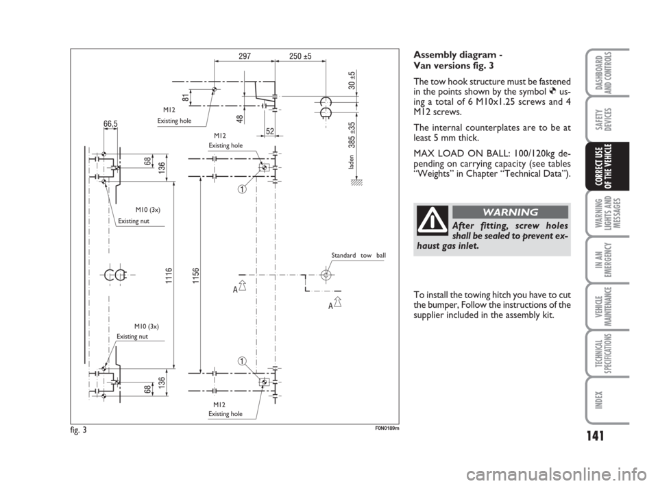
Assembly diagram -
Van versions fig. 3
The tow hook structure must be fastened
in the points shown by the symbol Øus-
ing a total of 6 M10x1.25 screws and 4
M12 screws.
The internal counterplates are to be at
least 5 mm thick.
MAX LOAD ON BALL: 100/120kg de-
pending on carrying capacity (see tables
“Weights” in Chapter “Technical Data”).
After fitting, screw holes
shall be sealed to prevent ex-
haust gas inlet.
WARNING
fig. 3F0N0189m
Existing hole
Existing nut
Existing nutExisting hole
Existing hole
laden
Standard tow ball M12
M12
M10 (3x)
M10 (3x)
M12
To install the towing hitch you have to cut
the bumper, Follow the instructions of the
supplier included in the assembly kit.
Page 143 of 282
142
WARNING
LIGHTS AND
MESSAGES
IN AN
EMERGENCY
VEHICLE
MAINTENANCE
TECHNICAL
SPECIFICATIONS
INDEX
DASHBOARD
AND CONTROLS
SAFETY
DEVICES
CORRECT USE
OF THE VEHICLE
fig. 4F0N0250m
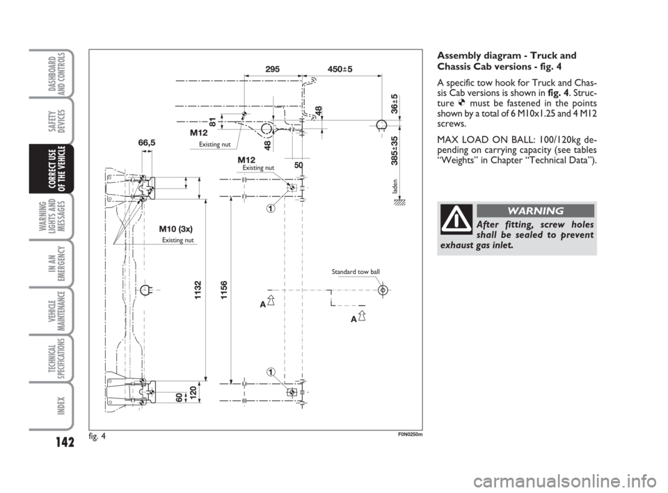
Assembly diagram - Truck and
Chassis Cab versions - fig. 4
A specific tow hook for Truck and Chas-
sis Cab versions is shown infig. 4. Struc-
ture Ømust be fastened in the points
shown by a total of 6 M10x1.25 and 4 M12
screws.
MAX LOAD ON BALL: 100/120kg de-
pending on carrying capacity (see tables
“Weights” in Chapter “Technical Data”).
After fitting, screw holes
shall be sealed to prevent
exhaust gas inlet.
WARNING
Existing nut
Existing nut
Existing nut
Standard tow ball
laden
Page 167 of 282
166
WARNING
LIGHTS AND
MESSAGES
VEHICLE
MAINTENANCE
TECHNICAL
SPECIFICATIONS
IINDEX
DASHBOARD
AND CONTROLS
SAFETY
DEVICES
CORRECT USE
OF THE
VEHICLE
IN AN
EMERGENCY
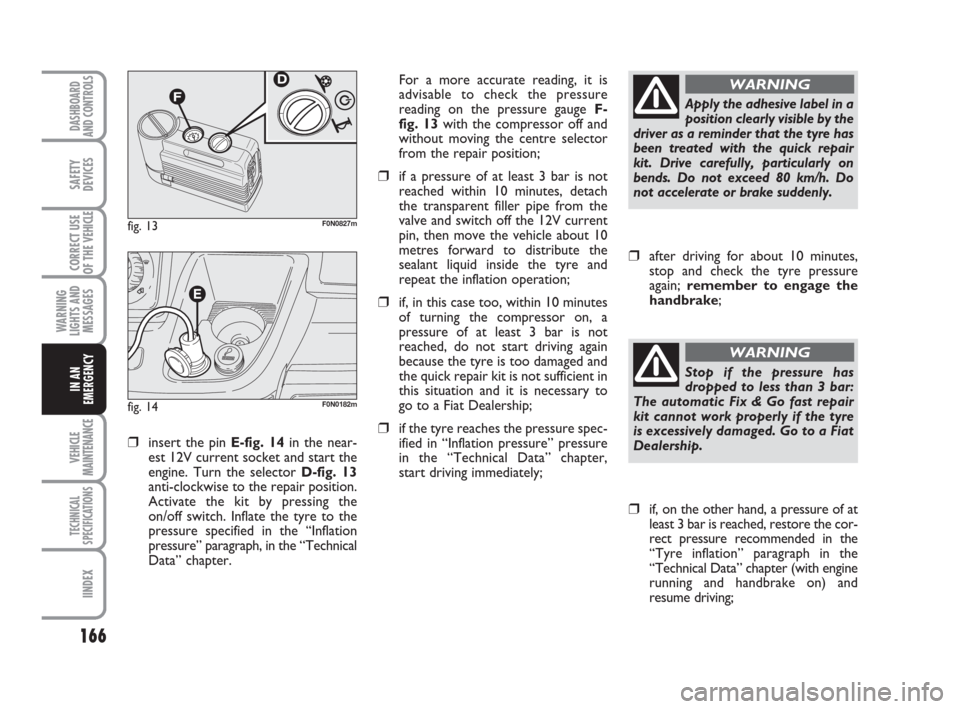
❒insert the pin E-fig. 14in the near-
est 12V current socket and start the
engine. Turn the selector D-fig. 13
anti-clockwise to the repair position.
Activate the kit by pressing the
on/off switch. Inflate the tyre to the
pressure specified in the “Inflation
pressure” paragraph, in the “Technical
Data” chapter.For a more accurate reading, it is
advisable to check the pressure
reading on the pressure gauge F-
fig. 13with the compressor off and
without moving the centre selector
from the repair position;
❒if a pressure of at least 3 bar is not
reached within 10 minutes, detach
the transparent filler pipe from the
valve and switch off the 12V current
pin, then move the vehicle about 10
metres forward to distribute the
sealant liquid inside the tyre and
repeat the inflation operation;
❒if, in this case too, within 10 minutes
of turning the compressor on, a
pressure of at least 3 bar is not
reached, do not start driving again
because the tyre is too damaged and
the quick repair kit is not sufficient in
this situation and it is necessary to
go to a Fiat Dealership;
❒if the tyre reaches the pressure spec-
ified in “Inflation pressure” pressure
in the “Technical Data” chapter,
start driving immediately;
fig. 13F0N0827m
fig. 14F0N0182m
Apply the adhesive label in a
position clearly visible by the
driver as a reminder that the tyre has
been treated with the quick repair
kit. Drive carefully, particularly on
bends. Do not exceed 80 km/h. Do
not accelerate or brake suddenly.
WARNING
❒after driving for about 10 minutes,
stop and check the tyre pressure
again; remember to engage the
handbrake;
❒if, on the other hand, a pressure of at
least 3 bar is reached, restore the cor-
rect pressure recommended in the
“Tyre inflation” paragraph in the
“Technical Data” chapter (with engine
running and handbrake on) and
resume driving;
Stop if the pressure has
dropped to less than 3 bar:
The automatic Fix & Go fast repair
kit cannot work properly if the tyre
is excessively damaged. Go to a Fiat
Dealership.
WARNING
Page 168 of 282
167
WARNING
LIGHTS AND
MESSAGES
VEHICLE
MAINTENANCE
TECHNICAL
SPECIFICATIONS
INDEX
DASHBOARD
AND CONTROLS
SAFETY
DEVICES
CORRECT USE
OF THE
VEHICLE
IN AN
EMERGENCY
❒drive with the utmost care to the
nearest Fiat Dealership.
FOR CHECKING AND
RESTORING PRESSURE ONLY
The compressor may also be used for
restoring pressure only.
❒Engage the handbrake
❒Undo the cap for the tyre valve, extract
the black pipe and tighten the ring nut
on the tyre valve.
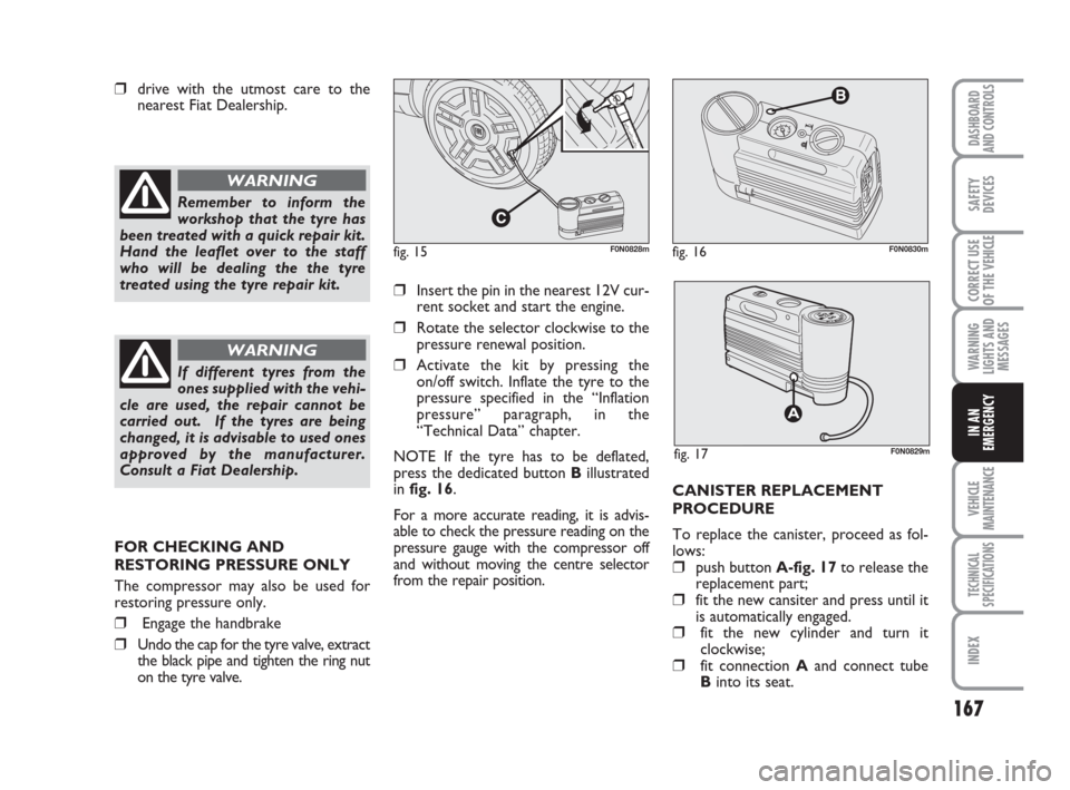
❒Insert the pin in the nearest 12V cur-
rent socket and start the engine.
❒Rotate the selector clockwise to the
pressure renewal position.
❒Activate the kit by pressing the
on/off switch. Inflate the tyre to the
pressure specified in the “Inflation
pressure” paragraph, in the
“Technical Data” chapter.
NOTE If the tyre has to be deflated,
press the dedicated button Billustrated
in fig. 16.
For a more accurate reading, it is advis-
able to check the pressure reading on the
pressure gauge with the compressor off
and without moving the centre selector
from the repair position.CANISTER REPLACEMENT
PROCEDURE
To replace the canister, proceed as fol-
lows:
❒push button A-fig. 17to release the
replacement part;
❒fit the new cansiter and press until it
is automatically engaged.
❒fit the new cylinder and turn it
clockwise;
❒fit connection Aand connect tube
Binto its seat.
Remember to inform the
workshop that the tyre has
been treated with a quick repair kit.
Hand the leaflet over to the staff
who will be dealing the the tyre
treated using the tyre repair kit.
WARNING
If different tyres from the
ones supplied with the vehi-
cle are used, the repair cannot be
carried out. If the tyres are being
changed, it is advisable to used ones
approved by the manufacturer.
Consult a Fiat Dealership.
WARNING
fig. 16
B
F0N0830m
fig. 17F0N0829m
fig. 15F0N0828m
Page 212 of 282
211
WARNING
LIGHTS AND
MESSAGES
INDEX
DASHBOARD
AND CONTROLS
SAFETY
DEVICES
CORRECT USE
OF THE
VEHICLE
IN AN
EMERGENCY
VEHICLE
MAINTENANCE
TECHNICAL
SPECIFICATIONS
IDENTIFICATION DATA ................................................. 212
ENGINE CODES - BODYWORK VERSIONS .............. 214
ENGINE .................................................................................. 216
FUEL FEED ............................................................................. 217
TRANSMISSION .................................................................. 217
BRAKES................................................................................... 218
SUSPENSIONS....................................................................... 218
STEERING............................................................................... 218
WHEELS.................................................................................. 219
DIMENSIONS......................................................................... 223
PERFORMANCE................................................................... 229
WEIGHTS............................................................................... 230
CAPACITIES .......................................................................... 261
FLUIDS AND LUBRICANTS.............................................. 262
FUEL CONSUMPTION....................................................... 264
CO
2EMISSIONS .................................................................. 265
RADIO FREQUENCY REMOTE CONTROL:
MINISTERIAL CERTIFICATIONS .................................... 266
TT T
E E
C C
H H
N N
I I
C C
A A
L L
S S
P P
E E
C C
I I
F F
I I
C C
A A
T T
I I
O O
N N
S S