trip computer FIAT DUCATO 2011 Owner handbook (in English)
[x] Cancel search | Manufacturer: FIAT, Model Year: 2011, Model line: DUCATO, Model: FIAT DUCATO 2011Pages: 287, PDF Size: 4.42 MB
Page 7 of 287
3
KNOWING
YOUR CAR
SAFETY
STARTING
AND
DRIVING
WARNING
LIGHTS AND
MESSAGES
IN AN
EMERGENCY
MAINTENANCE
AND CARE
TECHNICAL
SPECIFICATIONS
INDEX
KNOWING YOUR CAR
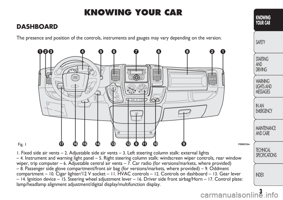
DASHBOARD
The presence and position of the controls, instruments and gauges may vary depending on the version.
1.Fixed side air vents –2.Adjustable side air vents – 3.Left steering column stalk: external lights
–
4.Instrument and warning light panel – 5.Right steering column stalk: windscreen wiper controls, rear window
wiper, trip computer –
6.Adjustable central air vents – 7.Car radio (for versions/markets, where provided)
–
8.Passenger side glove compartment/front air bag (for versions/markets, where provided) – 9.Oddment
compartment –
10.Cigar lighter/12 V socket – 11.HVAC controls – 12.Controls on dashboard – 13.Gear lever
–
14.Ignition device – 15. Steering wheel adjustment lever – 16.Driver side front airbag/Horn – 17.Control plate:
lamp/headlamp alignment adjustment/digital display/multifunction display.
F0N0510mFig. 1
Page 27 of 287
23
KNOWING
YOUR CAR
SAFETY
STARTING
AND
DRIVING
WARNING
LIGHTS AND
MESSAGES
IN AN
EMERGENCY
MAINTENANCE
AND CARE
TECHNICAL
SPECIFICATIONS
INDEX
– once you have selected the submenu to be changed,
press the button MODE briefly;
– when accessing the “Time” submenu:briefly press the
button MODE, “hours” will flash on the display;
– press button
▲or ▼to adjust;
– briefly press button MODE: “minutes” starts flashing
on the display;
– press button
▲or ▼to adjust;
– when accessing the “Format” submenu:briefly press
button MODE : the previously set display format will
flash on the display;
– press
▲or ▼to select 24h or 12h.
When you have made the required settings, briefly press
the MODE button to go back to the submenu screen or
hold the button down to go back to the main menu
screen without storing the new settings.
– press the MODE button again for a while to return to
the standard screen or to the main menu according to
where you are in the menu. Trip B On/Off (trip B data)
This function can be used to activate (On) or deactivate
(Off) the Trip B display (partial trip).
For further information see “Trip computer”.
Proceed as follows to switch the function on and off:
– briefly press button MODE: ON or OFF flashes on
the display (according to the previous setting);
– press button
▲or ▼to select;
– press the MODE button briefly to return to the menu
screen or press the button for longer to return to the
standard screen without memorising.
Setting the clock (Set time)
This function enables the clock to be set through two
submenus: “Time” and “Format”.
To carry out the adjustment, proceed as follows:
– briefly press the MODE button and two submenus,
“Time” and “Format”, are displayed;
– press
▲or ▼to move between the two submenus;
Page 33 of 287
29
KNOWING
YOUR CAR
SAFETY
STARTING
AND
DRIVING
WARNING
LIGHTS AND
MESSAGES
IN AN
EMERGENCY
MAINTENANCE
AND CARE
TECHNICAL
SPECIFICATIONS
INDEX
Values displayed
External temperature
Indicates the temperature outside the vehicle passenger
compartment.
Range (for versions/markets where provided)
It indicates the distance that can still be travelled based
on the fuel in the tank assuming that driving conditions
will not change. The message “---” will appear on the
display in the following cases:
– range value lower than 50 km (or 30 mi)
– vehicle left parked with engine running for long
period.
Trip distance
This value shows the distance covered from the start of
the new mission.
Average consumption (for versions/markets where provided)
This value shows the average consumption from the
start of the new mission.
Instant consumption (for versions/markets where provided)
This indicates instant fuel consumption and it is
constantly updated. The message “---” will appear on
the display if the vehicle is parked with the engine
running.
Average speed
Represents the average vehicle speed as a function of
the overall time elapsed since the start of a new mission.TRIP COMPUTER
General information
The “Trip computer” is used to display information on
vehicle operation when the key is turned to
MAR-ON.
This function allows you to define two separate trips,
called “Trip A” and “Trip B”, for monitoring the
vehicle’s “complete mission” (journey) in a reciprocally
independent manner. Both functions can be reset (reset
means start of a new journey).
“Trip A” is used to display the figures relating to:
– Outside temperature
– Range
– Trip distance
– Average consumption
– Current consumption
– Average speed
– Trip time (driving time).
“Trip B”, available on multifunction display only, is used
to display the figures relating to:
– Trip distance B
– Average consumption B
– Average speed B
– Trip time B (driving time).
NOTE “Trip B” function can be excluded (see paragraph
“Trip B on”). “Range” and “Instant consumption”
parameters cannot be reset.
Page 34 of 287
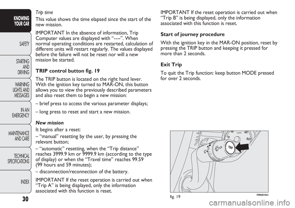
F0N0019mfig. 19
IMPORTANT If the reset operation is carried out when
“Trip B” is being displayed, only the information
associated with this function is reset.
Start of journey procedure
With the ignition key in the MAR-ON position, reset by
pressing the TRIP button and keeping it pressed for
more than 2 seconds.
Exit Trip
To quit the Trip function: keep button MODE pressed
for over 2 seconds. Trip time
This value shows the time elapsed since the start of the
new mission.
IMPORTANT In the absence of information, Trip
Computer values are displayed with “----”. When
normal operating conditions are restarted, calculation of
different units will restart regularly. The values displayed
before the failure will not be reset nor will a new
mission be started.
TRIP control button fig. 19
The TRIP button is located on the right hand lever.
With the ignition key turned to MAR-ON, this button
allows you to view the previously described parameters
and also reset them to begin a new mission:
– brief press to access the various parameter displays;
– long press to reset and start a new mission.
New mission
It begins after a reset:
– “manual” resetting by the user, by pressing the
relevant button;
– “automatic” resetting, when the “Trip distance”
reaches 3999.9 km or 9999.9 km (according to the type
of display) or when the “Travel time” reaches 99.59
(99 hours and 59 minutes);
– disconnection/reconnection of the battery.
IMPORTANT If the reset operation is carried out when
“Trip A” is being displayed, only the information
associated with this function is reset.
30
KNOWING
YOUR CAR
SAFETY
STARTING
AND
DRIVING
WARNING
LIGHTS AND
MESSAGES
IN AN
EMERGENCY
MAINTENANCE
AND CARE
TECHNICAL
SPECIFICATIONS
INDEX
Page 283 of 287
279
KNOWING
YOUR CAR
SAFETY
STARTING
AND
DRIVING
WARNING
LIGHTS AND
MESSAGES
IN AN
EMERGENCY
MAINTENANCE
AND CARE
TECHNICAL
SPECIFICATIONS
INDEX
Number plate lights (bulb
replacement) .......................... 192
Official type approval for radio
frequency remote control .... 269
On-board instruments
(panel) ..............................14-15
– engine coolant
temperature gauge ............. 16
– engine oil gauge .................. 17
– fuel level gauge..................... 16
– multifunction display ......... 18
– rev counter ......................... 15
– speedometer........................ 15
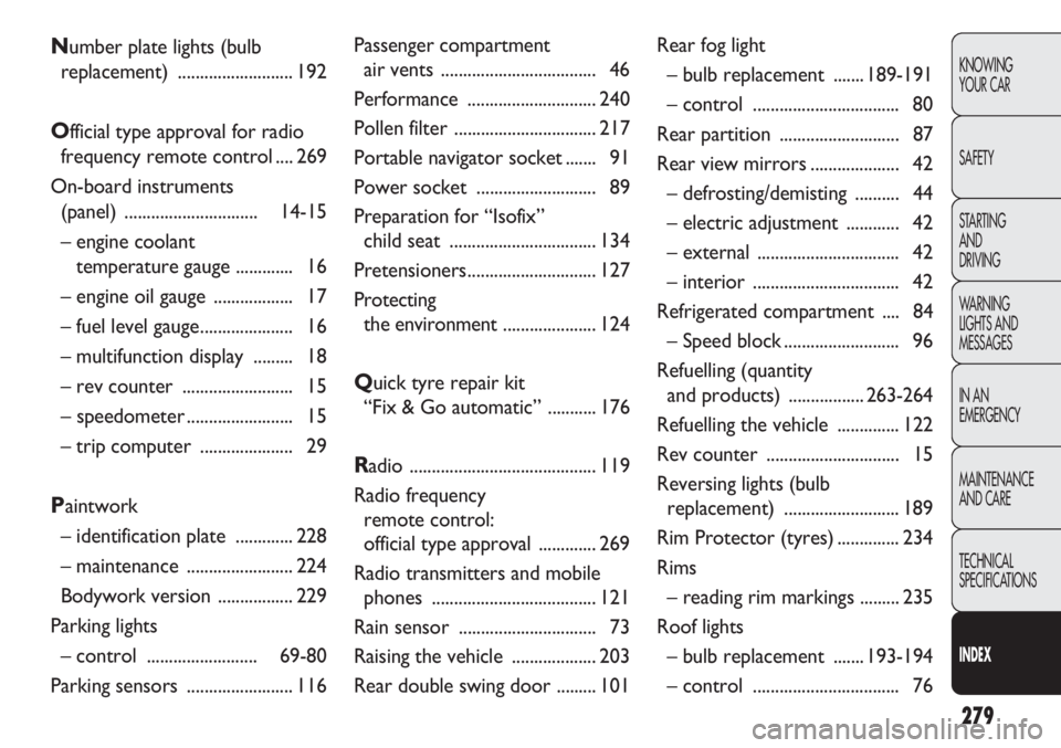
– trip computer ..................... 29
Paintwork
– identification plate ............. 228
– maintenance ........................ 224
Bodywork version ................. 229
Parking lights
– control ......................... 69-80
Parking sensors ........................ 116Passenger compartment
air vents ................................... 46
Performance ............................. 240
Pollen filter ................................ 217
Portable navigator socket ....... 91
Power socket ........................... 89
Preparation for “Isofix”
child seat ................................. 134
Pretensioners............................. 127
Protecting
the environment..................... 124
Quick tyre repair kit
“Fix & Go automatic” ........... 176
Radio .......................................... 119
Radio frequency
remote control:
official type approval ............. 269
Radio transmitters and mobile
phones ..................................... 121
Rain sensor ............................... 73
Raising the vehicle ................... 203
Rear double swing door ......... 101Rear fog light
– bulb replacement ....... 189-191
– control ................................. 80
Rear partition ........................... 87
Rear view mirrors.................... 42
– defrosting/demisting .......... 44
– electric adjustment ............ 42
– external ................................ 42
– interior ................................. 42
Refrigerated compartment .... 84
– Speed block .......................... 96
Refuelling (quantity
and products) .................263-264
Refuelling the vehicle .............. 122
Rev counter .............................. 15
Reversing lights (bulb
replacement) .......................... 189
Rim Protector (tyres).............. 234
Rims
– reading rim markings ......... 235
Roof lights
– bulb replacement ....... 193-194
– control ................................. 76
Page 285 of 287
281
KNOWING
YOUR CAR
SAFETY
STARTING
AND
DRIVING
WARNING
LIGHTS AND
MESSAGES
IN AN
EMERGENCY
MAINTENANCE
AND CARE
TECHNICAL
SPECIFICATIONS
INDEX
Top speeds ................................ 240
Towing the vehicle .................. 203
Traction Plus system ............... 114
Trailer (towing) ........................ 150
– installing the tow hook ..... 151
– warnings ............................... 151
Trailers (towing) ...................... 150
Transmission (specifications) ... 231
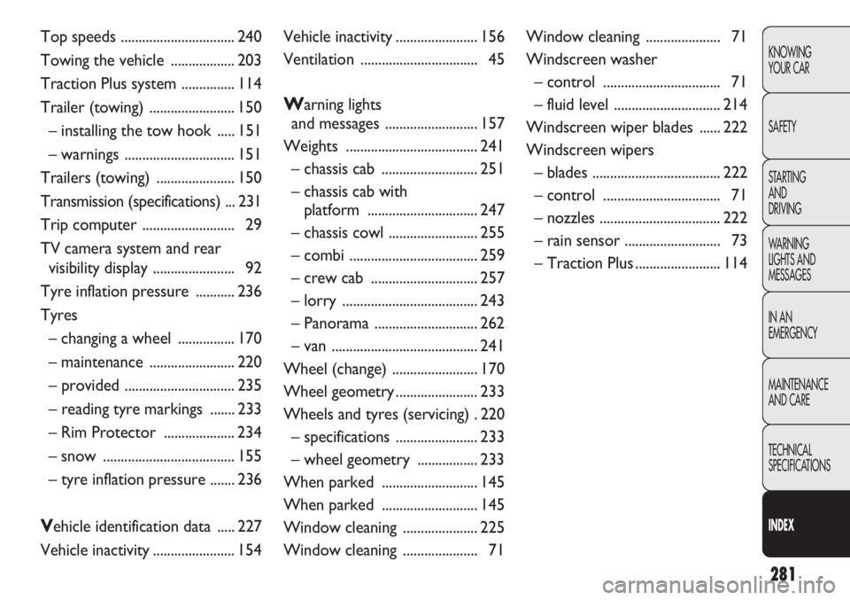
Trip computer .......................... 29
TV camera system and rear
visibility display ....................... 92
Tyre inflation pressure ........... 236
Tyres
– changing a wheel ................ 170
– maintenance ........................ 220
– provided ............................... 235
– reading tyre markings ....... 233
– Rim Protector .................... 234
– snow ..................................... 155
– tyre inflation pressure ....... 236
Vehicle identification data ..... 227
Vehicle inactivity....................... 154Vehicle inactivity....................... 156
Ventilation ................................. 45
Warning lights
and messages .......................... 157
Weights ..................................... 241
– chassis cab ........................... 251
– chassis cab with
platform ............................... 247
– chassis cowl ......................... 255
– combi .................................... 259
– crew cab .............................. 257
– lorry ...................................... 243
– Panorama ............................. 262
– van ......................................... 241
Wheel (change) ........................ 170
Wheel geometry....................... 233
Wheels and tyres (servicing) . 220
– specifications ....................... 233
– wheel geometry ................. 233
When parked ........................... 145
When parked ........................... 145
Window cleaning ..................... 225
Window cleaning ..................... 71Window cleaning ..................... 71
Windscreen washer
– control ................................. 71
– fluid level .............................. 214
Windscreen wiper blades ...... 222
Windscreen wipers
– blades .................................... 222
– control ................................. 71
– nozzles .................................. 222
– rain sensor ........................... 73
– Traction Plus ........................ 114