tyre FIAT DUCATO 2011 Owner handbook (in English)
[x] Cancel search | Manufacturer: FIAT, Model Year: 2011, Model line: DUCATO, Model: FIAT DUCATO 2011Pages: 287, PDF Size: 4.42 MB
Page 113 of 287
109
KNOWING
YOUR CAR
SAFETY
STARTING
AND
DRIVING
WARNING
LIGHTS AND
MESSAGES
IN AN
EMERGENCY
MAINTENANCE
AND CARE
TECHNICAL
SPECIFICATIONS
INDEX
FAILURE WARNING
ABS failure
ABS Failure is indicated by the
>warning light in the
instrument panel together with the dedicated message
in the multifunction display (for versions/markets where
provided) coming on (see “Warning lights and
messages” section).
In this case, the braking system will still be effective,
although without the extra capacity offered by the ABS
system. Drive carefully to the nearest Fiat Dealership to
have the system checked. SYSTEM INTERVENTION
The driver can tell the ABS system has come into action
because the brake pedal pulsates slightly and the system
gets noisier: it means that the vehicle speed should be
altered to suit the type of road surface.
If the ABS cuts in, it is a sign that the
grip between tyre and the road surface
has reached the limit: you must slow down to
match the speed to the road grip available.
WARNING
EBD failure
ABS Failure is indicated by the
>and xwarning lights
in the instrument panel together with the dedicated
message in the multifunction display (for versions/
markets where provided) coming on (see “Warning
lights and messages” section).
In this case, the rear wheels may suddenly lock and the
vehicle may swerve when braking sharply. Drive
carefully to the nearest Fiat Dealership to have the
system checked.
If only the xwarning light in the
instrument panel lights up (together with
a message in the multifunction display, for
versions/markets where provided) stop the
vehicle immediately and contact the nearest Fiat
Dealership. Fluid leaking from the hydraulic
system will compromise the operation of the
braking system, whether it is of the conventional
type or with ABS.
WARNING
Page 114 of 287
110
KNOWING
YOUR CAR
SAFETY
STARTING
AND
DRIVING
WARNING
LIGHTS AND
MESSAGES
IN AN
EMERGENCY
MAINTENANCE
AND CARE
TECHNICAL
SPECIFICATIONS
INDEX
ESP SYSTEM
(Electronic Stability Program)
(for versions/markets where provided)
This is an electronic system that controls vehicle
stability in the event of tyre grip loss, helping to maintain
directional control.
The ESP system is therefore particularly useful when
grip conditions of road surfaces change.
The MSR system (adjustment of the engine braking
torque during gear changes) and the HBA system
(automatic increase in the braking pressure during
emergency braking) are present with ESP, ASR and Hill
Holder systems (for versions/markets where provided).
SYSTEM INTERVENTION
This is signalled by the flashing of warning light
áin the
instrument panel, to inform the driver that the vehicle is
in critical stability and grip conditions.
SYSTEM ACTIVATION
The ESP system is automatically activated when the
vehicle is started and cannot be de-activated. BRAKE ASSIST (emergency braking assistance
integrated in ESP)
(for versions/markets where provided)
This system (which cannot be deactivated) recognises
emergency braking conditions according to the speed of
operation of the brake pedal and provides an additional
hydraulic braking pressure to support that provided by
the driver. This allows faster and more powerful
operation of the braking system.
The Brake Assist is deactivated on versions equipped
with ESP, in the event of an ESP system failure (indicated
by warning light
áswitching on together with the
message in the multifunction display, for
versions/markets where provided).
When the ABS intervenes and you notice
the brake pedal pulsating, do not be
afraid to keep the pedal pushed down. This will
help you to stop in the shortest distance
possible, depending on the road conditions.
WARNING
Page 115 of 287
111
KNOWING
YOUR CAR
SAFETY
STARTING
AND
DRIVING
WARNING
LIGHTS AND
MESSAGES
IN AN
EMERGENCY
MAINTENANCE
AND CARE
TECHNICAL
SPECIFICATIONS
INDEX
❒downhill: vehicle stationary on a road with a gradient
higher than 5%, engine running, clutch and brake
pedal pressed and reverse gear engaged.
At pickup the
ESPsystem control unit will maintain the
braking pressure at the wheels until the necessary torque
for starting is reached or, in any case, for a maximum of
2 seconds in order to move easily from the brake pedal
to the accelerator pedal. When two seconds have
elapsed, without starting, the system is automatically
deactivated, gradually releasing the braking pressure.
During this release stage, the typical brake
disengagement noise indicating that the vehicle is going
to move imminently will be heard.
Failure warning
The
áwarning light in the instrument panel will come
on in the event of a failure (see “Warning lights and
messages” section).
IMPORTANT The Hill Holder system is not a parking
brake; therefore, never leave the vehicle without having
engaged the handbrake, turned the engine off and
engaged first gear. FAILURE WARNING
In the event of a failure, the ESP will be automatically
switched off and the áwarning light will come on
constantly in the instrument panel along with a message
in the multifunction display (for versions/markets where
provided) (see “Warning lights and messages” section).
The LED in the ASR OFF button will light up. Contact
a Fiat Dealership as soon as possible if this happens.
Do not take unnecessary risks, even if
your vehicle is fitted with an ESP system.
Your driving style must always be suited to the
road conditions, visibility and traffic. The driver
is ultimately responsible for road safety.
WARNING
HILL HOLDER SYSTEM
This system is an integral part of the
ESPsystem and it is
provided to facilitate starting on hills.
It is automatically activated in the following conditions:
❒uphill: vehicle stationary on a road with a gradient
higher than 5%, engine running, clutch and brake
pedal pressed, gearbox in neutral or gear other than
reverse engaged;
For the correct operation of the ESP and
ASR systems, the tyres must absolutely be
the same make and type on all wheels, in perfect
condition and, above all, of the type, make and
size specified.
WARNING
Page 116 of 287
112
KNOWING
YOUR CAR
SAFETY
STARTING
AND
DRIVING
WARNING
LIGHTS AND
MESSAGES
IN AN
EMERGENCY
MAINTENANCE
AND CARE
TECHNICAL
SPECIFICATIONS
INDEX
MSR system
(engine braking torque control)
This is an integral part of the ASR system that, in the
event of a sudden gear down shift, cuts in and provides
torque to the engine thus preventing excessive drive
wheel drive which, especially in poor grip conditions,
can lead to a loss of stability. ASR SYSTEM (Antislip Regulator)
This is a traction control system that cuts in
automatically every time one or both drive wheels slip.
Depending on the slipping conditions, two different
control systems are activated:
❒if the slipping involves both drive wheels, the ASR
function intervenes by reducing the power
transmitted by the engine;
❒if the slipping only involves only one driving wheel,
the ASR system cuts in by automatically braking the
wheel that is slipping.
The action of the
ASRis particularly helpful in the
following circumstances:
❒slipping of the inner wheel when cornering due to
the effect of dynamic load changes or excessive
acceleration;
❒too much power transmitted to the wheels also in
relation to the conditions of the road surface;
❒acceleration on slippery, snowy or icy surfaces;
❒loss of grip on a wet surface (aquaplaning).
For the correct operation of the ESP and
ASR systems, the tyres must absolutely be
the same make and type on all wheels, in perfect
condition and, above all, of the type, make and
size specified.
WARNING
Page 123 of 287
119
KNOWING
YOUR CAR
SAFETY
STARTING
AND
DRIVING
WARNING
LIGHTS AND
MESSAGES
IN AN
EMERGENCY
MAINTENANCE
AND CARE
TECHNICAL
SPECIFICATIONS
INDEX
F0N0157mfig. 132
SOUND SYSTEM
(for versions/markets, where provided)
For radio operation, consult the Supplement attached to
this Owner Handbook.
SOUND SYSTEM CAPABILITY
(for versions/markets where provided)
The system consists of:
❒sound system power cables
❒front speaker connection cables
❒aerial power cable
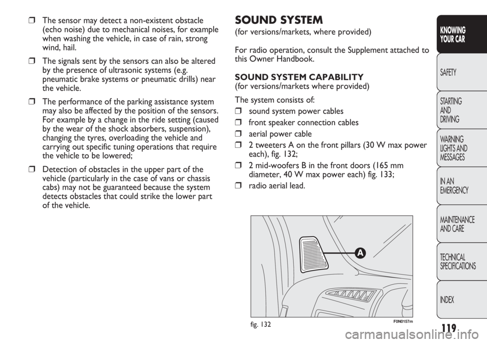
❒2 tweeters A on the front pillars (30 W max power
each), fig. 132;
❒2 mid-woofers B in the front doors (165 mm
diameter, 40 W max power each) fig. 133;
❒radio aerial lead.
❒The sensor may detect a non-existent obstacle
(echo noise) due to mechanical noises, for example
when washing the vehicle, in case of rain, strong
wind, hail.
❒The signals sent by the sensors can also be altered
by the presence of ultrasonic systems (e.g.
pneumatic brake systems or pneumatic drills) near
the vehicle.
❒The performance of the parking assistance system
may also be affected by the position of the sensors.
For example by a change in the ride setting (caused
by the wear of the shock absorbers, suspension),
changing the tyres, overloading the vehicle and
carrying out specific tuning operations that require
the vehicle to be lowered;
❒Detection of obstacles in the upper part of the
vehicle (particularly in the case of vans or chassis
cabs) may not be guaranteed because the system
detects obstacles that could strike the lower part
of the vehicle.
Page 152 of 287
148
KNOWING
YOUR CAR
SAFETY
STARTING
AND
DRIVING
WARNING
LIGHTS AND
MESSAGES
IN AN
EMERGENCY
MAINTENANCE
AND CARE
TECHNICAL
SPECIFICATIONS
INDEX
CONTAINING RUNNING COSTS
Here are some suggestions which may help you to keep
the running costs of your vehicle down and lower the
amount of toxic emissions released into the
atmosphere.
GENERAL CONSIDERATIONS
Vehicle maintenance
Have checks and adjustments carried out in accordance
with the “Scheduled Servicing Plan”.
Tyres
Check the pressure of the tyres routinely at an interval
of no more than 4 weeks: if the pressure is too low,
consumption levels increase as resistance to rolling is
higher.
Unnecessary loads
Do not travel with an overloaded boot. The weight of
the vehicle (especially when driving in town) and its
geometry greatly affect fuel consumption and stability.
Roof rack/ski rack
Remove the roof rack or the ski rack from the roof
after use. These accessories decrease aerodynamic
penetration of the vehicle and have a negative effect on
fuel consumption. It is better to use a trailer, particularly
for transporting bulky objects. In addition to these general precautions, some simple
precautions can improve driving safety, travelling
comfort and vehicle durability:
❒distribute the load evenly over the floor: if it is
necessary to concentrate it in a single area, choose
an area mid-way between both axles;
❒remember that the lower the load, the lower the
vehicle’s centre of gravity, making for a safer drive:
therefore always position the heaviest goods lower
down;
❒lastly, remember that the vehicle’s dynamic
behaviour is affected by the weight transported:
in particular, the stopping distances are longer,
especially at high speed.
If you wish to carry petrol in a reserve
tank, observe the legal restrictions and
only use a tank that is type approved and
properly secured to the load anchorage
eyebolts. However, the risk of fire in the event
of an accident increases.
WARNING
Page 159 of 287
155
KNOWING
YOUR CAR
SAFETY
STARTING
AND
DRIVING
WARNING
LIGHTS AND
MESSAGES
IN AN
EMERGENCY
MAINTENANCE
AND CARE
TECHNICAL
SPECIFICATIONS
INDEX
SNOW CHAINS
The use of snow chains should be in compliance with
local regulations. The snow chains may be applied only
onto the front wheel tyres (drive wheels). Use of
Lineaccessori Fiat snow chains is recommended. Check
the tension of the snow chains after the first few metres
have been driven.
IMPORTANT With snow chains, use the accelerator
with extreme care to prevent or to limit as much as
possible slipping of the drive wheels which could cause
the chains to break resulting in damage to the car body
or mechanical components.
IMPORTANT Use reduced-size snow chains.
SNOW TYRES
Fiat Dealerships will be happy to provide advice
concerning the most suitable type of tyres for the
customer’s requirements. The performance of these
tyres is considerably reduced when the tread depth is
less than 4 mm. Replace them in this case. Due to snow
tyre features, under normal conditions of use or on long
motorway journeys, the performance of these tyres is
much lower than that of standard tyres. Limit
performance according to the use for which they were
certified.
IMPORTANT When using snow tyres with a maximum
speed index below the one that can be reached by the
vehicle (increased by 5%), place a notice in the
passenger compartment, plainly in view, which states the
maximum speed allowed by the snow tyres (as per EC
Directive).
All four tyres should be the same (brand and track) to
ensure greater safety when driving and braking and better
driveability. Remember that it is inappropriate to change
the rotation direction of tyres.
The max speed for snow tyres with “Q”
marking is 160 km/h; 190 km/h for tyres
with “T” marking and 210 km/h for tyres with H
marking. The Highway Code speed limits must
however be always strictly observed.
WARNING
Keep your speed down when snow
chains are fitted. Do not exceed
50 km/h. Avoid potholes, steps and
pavements and also avoid driving long
distances on roads not covered with
snow in order to prevent damaging the vehicle
and the roadbed.
WARNING
Page 160 of 287
❒cover the vehicle with a piece of fabric or perforated
plastic sheet. Do not use compact plastic tarpaulins,
which prevent humidity from evaporating from the
surface of the vehicle;
❒inflate tyres to a pressure of +0.5 bar above the
normal specified pressure and check it at intervals;
❒if you don’t disconnect the battery from the electric
system, check its charge every month and recharge it
if the optical indicator shows a dark colour without
the central green area;
❒do not drain the engine cooling system.
IMPORTANT If the vehicle is equipped with an alarm
system, switch off the vehicle alarm with the remote
control.
LONG VEHICLE INACTIVITY
If the vehicle needs to be off the road for longer than
one month, the following precautions must be taken:
❒park the vehicle indoors in a dry and, possibly, well-
ventilated place;
❒engage a gear;
❒check that the handbrake is not engaged;
❒disconnect the negative battery terminal and check
battery charge. Repeat this check once every three
months during storage. Recharge if the optical
indicator shows a dark colour without the central
green area (see “Battery recharging” in the section
“Dashboard and controls”); If the vehicle is equipped
with a battery disconnection function (disconnector),
see the description of the procedure in the
“Controls” paragraph in the “Dashboard and
controls” section;
❒clean and protect the painted parts using protective
wax;
❒clean and protect the shiny metal parts using special
commercially-available compounds;
❒sprinkle talcum powder on the rubber windscreen
and rear window wiper blades and lift them off
the glass;
❒slightly open the windows;
156
CONOSCENZA
DEL
VEICOLO
SICUREZZA
AVVIAMENTO
E GUIDA
SPIE E
MESSAGGI
IN EMERGENZA
MANUTENZIONE
E CURA
DATI TECNICI
INDICE
Page 175 of 287
171
KNOWING
YOUR CAR
SAFETY
STARTING
AND
DRIVING
WARNING
LIGHTS AND
MESSAGES
IN AN
EMERGENCY
MAINTENANCE
AND CARE
TECHNICAL
SPECIFICATIONS
INDEX
Please note that:
❒the jack weight is 4.5 kg;
❒the jack requires no adjustment;
❒the jack cannot be repaired. If it breaks it must be
replaced with a new jack;
❒no tool other than its cranking device may be fitted
on the jack.
Repair and refit the standard wheel as
soon as possible. Do not apply grease to
the bolt threading before assembly: they might
come unscrewed.
WARNING
The jack may only be used to replace
wheels on the car which it equips or
other cars of the same model. Never use the
jack for other purposes, such as lifting other car
models. Never use the jack to carry out repairs
under the vehicle. Incorrect positioning of the
jack may cause the lifted vehicle to fall. Do not
use the jack for loads higher than those shown
on the label.
WARNING
Never tamper with the inflation valve.
Never introduce tools of any kind
between rim and tyre. Check tyre and spare
wheel pressure regularly referring to the values
shown in the “Technical Specifications” section.
WARNING
No tools other than the crank provided
should be used with the spare wheel
lifting device; it should be operated by hand
only.
WARNING
To change a wheel proceed as follows:
❒stop the vehicle in a position where it does not pose
a danger for on-coming traffic and where you can
replace the wheel safely. The ground must be flat
and sufficiently compact;
❒turn the engine off and pull up the handbrake;
❒engage first gear or reverse;
❒wear the reflecting safety jacket (compulsory by law
in certain countries) before getting out of the
vehicle;
Page 178 of 287
174
KNOWING
YOUR CAR
SAFETY
STARTING
AND
DRIVING
WARNING
LIGHTS AND
MESSAGES
IN AN
EMERGENCY
MAINTENANCE
AND CARE
TECHNICAL
SPECIFICATIONS
INDEX
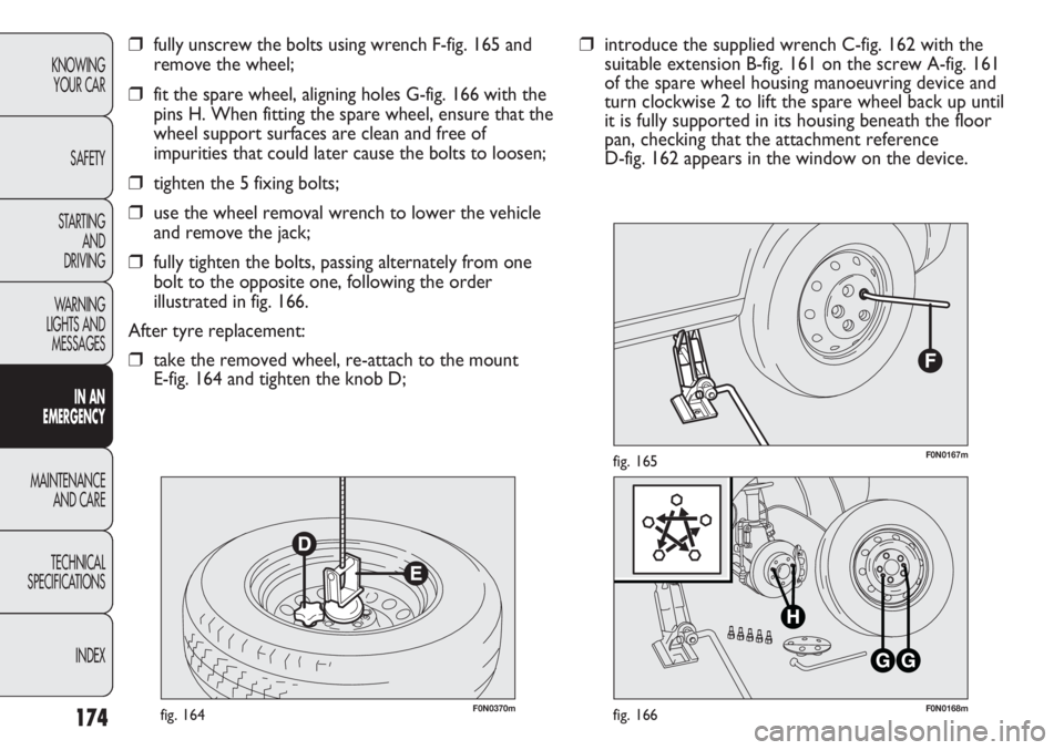
F0N0370mfig. 164F0N0168mfig. 166
F0N0167mfig. 165
❒introduce the supplied wrench C-fig. 162 with the
suitable extension B-fig. 161 on the screw A-fig. 161
of the spare wheel housing manoeuvring device and
turn clockwise 2 to lift the spare wheel back up until
it is fully supported in its housing beneath the floor
pan, checking that the attachment reference
D-fig. 162 appears in the window on the device.❒fully unscrew the bolts using wrench F-fig. 165 and
remove the wheel;
❒fit the spare wheel, aligning holes G-fig. 166 with the
pins H. When fitting the spare wheel, ensure that the
wheel support surfaces are clean and free of
impurities that could later cause the bolts to loosen;
❒tighten the 5 fixing bolts;
❒use the wheel removal wrench to lower the vehicle
and remove the jack;
❒fully tighten the bolts, passing alternately from one
bolt to the opposite one, following the order
illustrated in fig. 166.
After tyre replacement:
❒take the removed wheel, re-attach to the mount
E-fig. 164 and tighten the knob D;