button FIAT DUCATO 2014 3.G Owner's Guide
[x] Cancel search | Manufacturer: FIAT, Model Year: 2014, Model line: DUCATO, Model: FIAT DUCATO 2014 3.GPages: 367, PDF Size: 20.39 MB
Page 64 of 367
CUP HOLDER - CAN
HOLDER
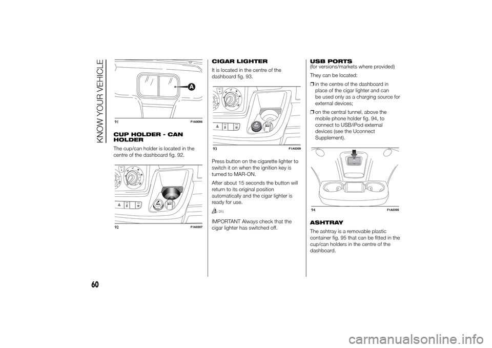
The cup/can holder is located in the
centre of the dashboard fig. 92.CIGAR LIGHTER
It is located in the centre of the
dashboard fig. 93.
Press button on the cigarette lighter to
switch it on when the ignition key is
turned to MAR-ON.
After about 15 seconds the button will
return to its original position
automatically and the cigar lighter is
ready for use.
31)
IMPORTANT Always check that the
cigar lighter has switched off.USB PORTS
(for versions/markets where provided)
They can be located:
❒in the centre of the dashboard in
place of the cigar lighter and can
be used only as a charging source for
external devices;
❒on the central tunnel, above the
mobile phone holder fig. 94, to
connect to USB/iPod external
devices (see the Uconnect
Supplement).
ASHTRAY
The ashtray is a removable plastic
container fig. 95 that can be fitted in the
cup/can holders in the centre of the
dashboard.
91
F1A0096
92
F1A0307
93
F1A0309
94
F1A0395
60
KNOW YOUR VEHICLE
Page 68 of 367
SPEED BLOCK(for versions/markets, where provided)
The vehicle is equipped with a speed
limitation function that can be set at the
user's request to one of 4 predefined
values: 90, 100, 110, 130 km/h.
To activate/deactivate this function,
contact a Fiat Dealership.
Following the operation, a sticker will be
applied to the windscreen showing the
maximum speed setting.
IMPORTANT The speedometer could
indicate a higher maximum speed than
the effective one, set by the Dealership,
in accordance with the regulations in
force.
SELF-LEVELLING AIR
SUSPENSIONGENERAL INFORMATION
The system only acts on the rear
wheels.
The system maintains the rear ride
setting for the vehicle constant in any
loading condition, while ensuring a
greater driving comfort. In addition, the
system allows the height of the vehicle
to be adjusted with the vehicle
stationary, by selecting from 7 different
positions to facilitate access to the
rear compartment.
HEIGHT ADJUSTMENT
There are 7 pre-defined levels for the
free height from the ground: from “ride
-3” to “ride 0” till “ride +3”.
The multifunction display, located in the
middle of the instrument panel, can
show the ride position.
Automatic adjustment
When moving, the system automatically
shows that the vehicle is in 'ride setting
0' and keeps it constant.
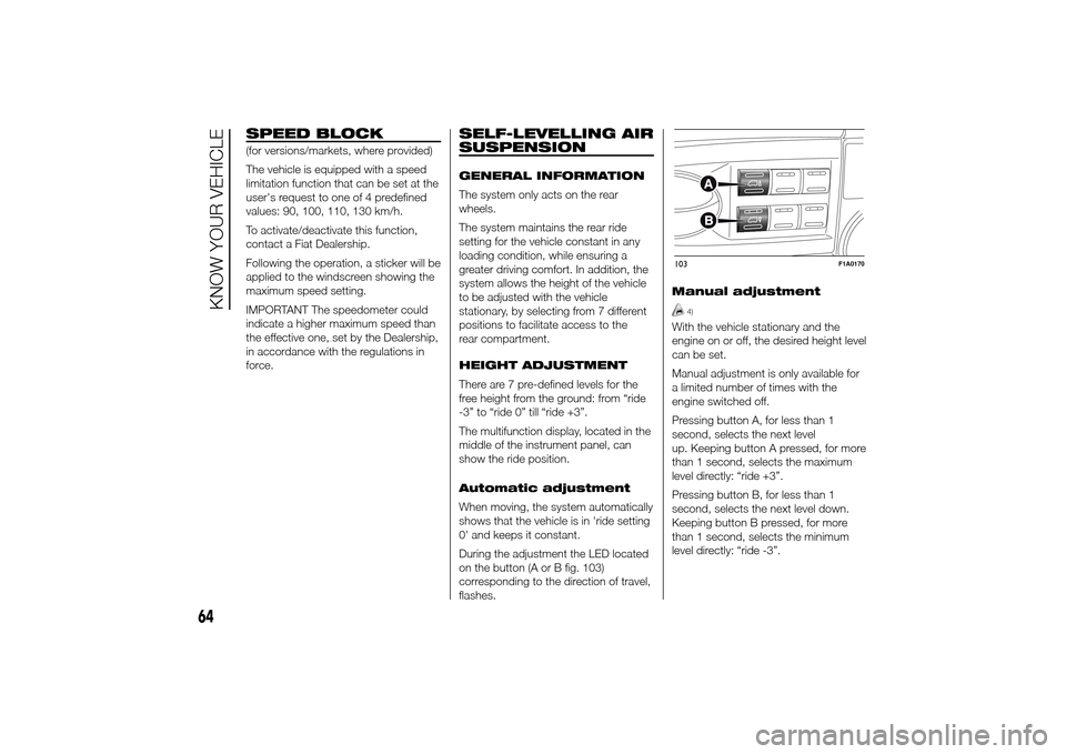
During the adjustment the LED located
on the button (A or B fig. 103)
corresponding to the direction of travel,
flashes.Manual adjustment
4)
With the vehicle stationary and the
engine on or off, the desired height level
can be set.
Manual adjustment is only available for
a limited number of times with the
engine switched off.
Pressing button A, for less than 1
second, selects the next level
up. Keeping button A pressed, for more
than 1 second, selects the maximum
level directly: “ride +3”.
Pressing button B, for less than 1
second, selects the next level down.
Keeping button B pressed, for more
than 1 second, selects the minimum
level directly: “ride -3”.103
F1A0170
64
KNOW YOUR VEHICLE
Page 69 of 367
During the adjustment the LED located
on the button (A or B) corresponding
to the direction of travel, flashes.
If, after selecting a button, the LED
remains lit up (for about 5 seconds)
rather than flashing, this means that the
adjustment is temporarily unavailable.
Possible causes may be as follows:
❒insufficient air reserve: the function is
restored by starting the engine;
❒the system has reached a threshold
working temperature: wait a few
minutes to let it cool down before
operating the buttons again.
The level selected with the vehicle
stationary is maintained up to a speed
of about 20 km/h; when this speed
is exceeded, the system will
automatically restore the normal level:
“ride 0”.
IMPORTANT
4) Before manually adjusting with
doors open, make sure there is
enough space around the vehicle
for this kind of operation.
DOORSDOOR CENTRAL
LOCKING/UNLOCKING
Locking doors from the
outside
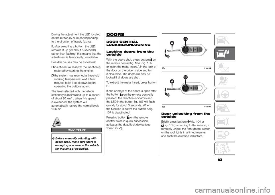
With the doors shut, press button
on
the remote control fig. 104 - fig. 105
or insert the metal insert A in the lock of
the door on the driver's side and turn
it clockwise. The doors will only be
locked if all doors are shut.
To extract the metal insert, press button
B.
If one or more of the doors is open after
the button
on the remote control is
pressed, the direction indicators and
the LED in the button fig. 107 will flash
quickly for about 3 seconds. When
the function is active the button A fig.
107 is deactivated.
Pressing button
on the remote
control twice in quick succession
activates the dead lock device (see
"Dead lock").Door unlocking from the
outside
Briefly press button
fig. 104 or
fig. 105, according to the version, to
remotely unlock the front doors, switch
on the roof lights in a timed manner
and flash the direction indicators.104
F1A0112
105
F1A0113
65
Page 70 of 367
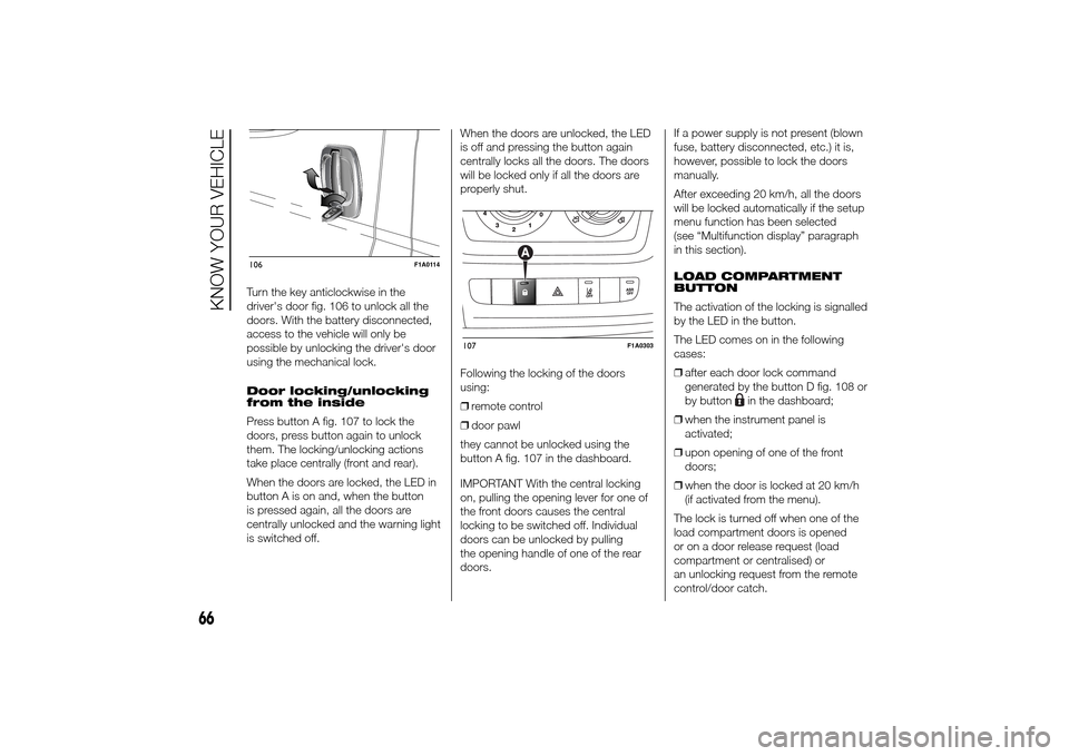
Turn the key anticlockwise in the
driver's door fig. 106 to unlock all the
doors. With the battery disconnected,
access to the vehicle will only be
possible by unlocking the driver's door
using the mechanical lock.
Door locking/unlocking
from the inside
Press button A fig. 107 to lock the
doors, press button again to unlock
them. The locking/unlocking actions
take place centrally (front and rear).
When the doors are locked, the LED in
button A is on and, when the button
is pressed again, all the doors are
centrally unlocked and the warning light
is switched off.When the doors are unlocked, the LED
is off and pressing the button again
centrally locks all the doors. The doors
will be locked only if all the doors are
properly shut.
Following the locking of the doors
using:
❒remote control
❒door pawl
they cannot be unlocked using the
button A fig. 107 in the dashboard.
IMPORTANT With the central locking
on, pulling the opening lever for one of
the front doors causes the central
locking to be switched off. Individual
doors can be unlocked by pulling
the opening handle of one of the rear
doors.If a power supply is not present (blown
fuse, battery disconnected, etc.) it is,
however, possible to lock the doors
manually.
After exceeding 20 km/h, all the doors
will be locked automatically if the setup
menu function has been selected
(see “Multifunction display” paragraph
in this section).
LOAD COMPARTMENT
BUTTON
The activation of the locking is signalled
by the LED in the button.
The LED comes on in the following
cases:
❒after each door lock command
generated by the button D fig. 108 or
by button
in the dashboard;
❒when the instrument panel is
activated;
❒upon opening of one of the front
doors;
❒when the door is locked at 20 km/h
(if activated from the menu).
The lock is turned off when one of the
load compartment doors is opened
or on a door release request (load
compartment or centralised) or
an unlocking request from the remote
control/door catch.
106
F1A0114
107
F1A0303
66
KNOW YOUR VEHICLE
Page 71 of 367
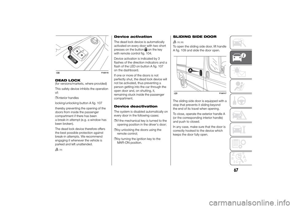
DEAD LOCK
(for versions/markets, where provided)
This safety device inhibits the operation
of:
❒interior handles
locking/unlocking button A fig. 107
thereby preventing the opening of the
doors from inside the passenger
compartment if there has been
a break-in attempt (e.g. a window has
been broken).
The dead lock device therefore offers
the best possible protection against
break-in attempts. We recommend
engaging it whenever the vehicle is
parked and left unattended.
34)
Device activation
The dead lock device is automatically
activated on every door with two short
presses on the button
on the key
with remote control fig. 104.
Device activation is indicated by 3
flashes of the direction indicators and a
flash of the LED on button A fig. 107
on the dashboard.
If one or more of the doors is not
perfectly shut, the dead lock device will
not be activated, thus preventing a
person getting into the car through the
open door and, on shutting, it,
remaining stuck inside the passenger
compartment.
Device deactivation
The system is disabled automatically on
every door in the following cases:
❒if the mechanical key is turned to the
opening position in the driver's door;
❒by unlocking the doors using the
remote control;
❒by turning the ignition key to the
MAR-ON position.SLIDING SIDE DOOR
35) 36)
To open the sliding side door, lift handle
A fig. 109 and slide the door open.
The sliding side door is equipped with a
stop that prevents it sliding beyond
the end of its travel when opening.
To close, operate the exterior handle A
(or the corresponding interior handle)
and push to closed.
In any case, make sure that the door is
correctly hooked to the device which
keeps the door fully open.
108
F1A0116
109
F1A0117
67
Page 72 of 367
SLIDING SIDE WINDOW
(for versions/markets, where provided)
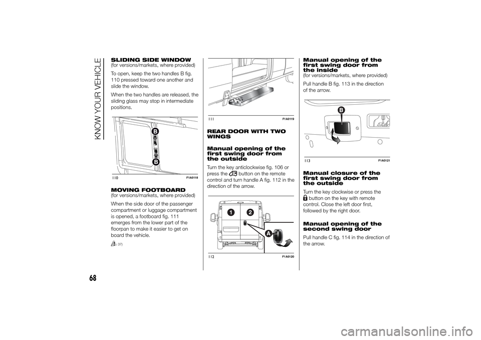
To open, keep the two handles B fig.
110 pressed toward one another and
slide the window.
When the two handles are released, the
sliding glass may stop in intermediate
positions.
MOVING FOOTBOARD
(for versions/markets, where provided)
When the side door of the passenger
compartment or luggage compartment
is opened, a footboard fig. 111
emerges from the lower part of the
floorpan to make it easier to get on
board the vehicle.
37)
REAR DOOR WITH TWO
WINGS
Manual opening of the
first swing door from
the outside
Turn the key anticlockwise fig. 106 or
press the
button on the remote
control and turn handle A fig. 112 in the
direction of the arrow.Manual opening of the
first swing door from
the inside
(for versions/markets, where provided)
Pull handle B fig. 113 in the direction
of the arrow.
Manual closure of the
first swing door from
the outside
Turn the key clockwise or press the
button on the key with remote
control. Close the left door first,
followed by the right door.
Manual opening of the
second swing door
Pull handle C fig. 114 in the direction of
the arrow.
110
F1A0118
111
F1A0119
112
F1A0120
113
F1A0121
68
KNOW YOUR VEHICLE
Page 73 of 367
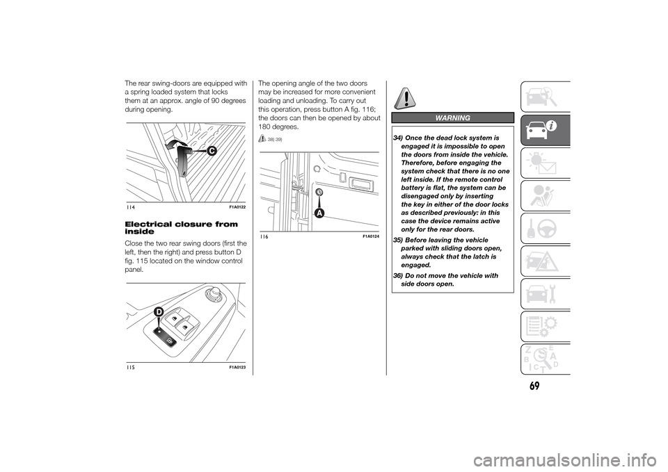
The rear swing-doors are equipped with
a spring loaded system that locks
them at an approx. angle of 90 degrees
during opening.
Electrical closure from
inside
Close the two rear swing doors (first the
left, then the right) and press button D
fig. 115 located on the window control
panel.The opening angle of the two doors
may be increased for more convenient
loading and unloading. To carry out
this operation, press button A fig. 116;
the doors can then be opened by about
180 degrees.
38) 39)
WARNING
34) Once the dead lock system is
engaged it is impossible to open
the doors from inside the vehicle.
Therefore, before engaging the
system check that there is no one
left inside. If the remote control
battery is flat, the system can be
disengaged only by inserting
the key in either of the door locks
as described previously: in this
case the device remains active
only for the rear doors.
35) Before leaving the vehicle
parked with sliding doors open,
always check that the latch is
engaged.
36) Do not move the vehicle with
side doors open.
114
F1A0122
115
F1A0123
116
F1A0124
69
Page 74 of 367
37) Before setting off after parking
or before moving the vehicle in
any way, ensure that the
footboard is fully stowed away. As
the movement of the platform is
linked to that of the sliding side
door, the
warning light in the
instrument panel comes on if it is
not fully retracted in the same
way as when the rear doors are
not shut.
38) This spring loaded system has
activation forces that were
designed for optimum comfort.
Accidental knocks or a strong
gust of wind may release the
springs and close the doors
spontaneously.
39) With the doors opened to 180
degrees, no locking system is
effective. Do not use this opening
with the vehicle parked on a
gradient or when it is windy.
ELECTRIC WINDOWSELECTRIC
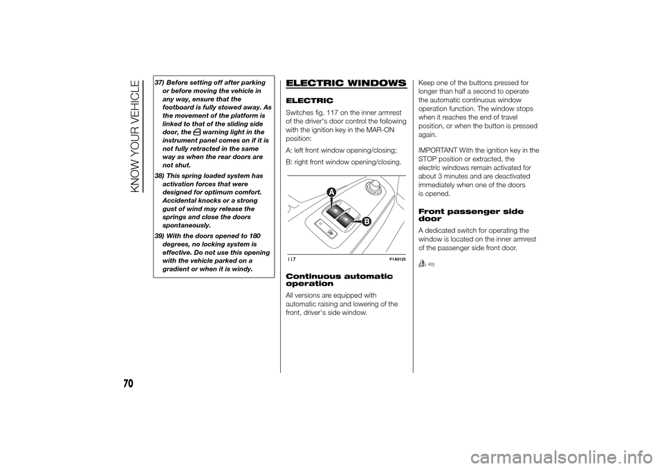
Switches fig. 117 on the inner armrest
of the driver's door control the following
with the ignition key in the MAR-ON
position:
A: left front window opening/closing;
B: right front window opening/closing.
Continuous automatic
operation
All versions are equipped with
automatic raising and lowering of the
front, driver's side window.Keep one of the buttons pressed for
longer than half a second to operate
the automatic continuous window
operation function. The window stops
when it reaches the end of travel
position, or when the button is pressed
again.
IMPORTANT With the ignition key in the
STOP position or extracted, the
electric windows remain activated for
about 3 minutes and are deactivated
immediately when one of the doors
is opened.
Front passenger side
door
A dedicated switch for operating the
window is located on the inner armrest
of the passenger side front door.
40)
117
F1A0125
70
KNOW YOUR VEHICLE
Page 80 of 367
❒ASR
❒HBA
❒DST
❒ERM
54) 55) 56)
SYSTEM INTERVENTION
This is signalled by the flashing of
warning light
in the instrument panel,
to inform the driver that the vehicle is
in critical stability and grip conditions.
SYSTEM ACTIVATION
The ESC system switches on
automatically when the engine is
started and cannot be switched off.
HILL HOLDER SYSTEM
This system is an integral part of the
ESC system and facilitates starting on
slopes.
It is automatically activated in the
following conditions:
❒uphill: vehicle stationary on a road
with a gradient higher than 5%,
engine running, brake pressed and
gearbox in neutral or gear (other than
reverse) engaged;❒downhill: vehicle stationary on a road
with a gradient higher than 5%,
engine running, brake pressed and
reverse gear engaged.
When setting off, the ESC system
control unit maintains the braking
pressure on the wheels until the torque
necessary for starting is reached, or
in any case for a maximum of 2
seconds, allowing your right foot to be
moved easily from the brake pedal to
the accelerator.
When two seconds have elapsed,
without starting, the system is
automatically deactivated, gradually
releasing the braking pressure. During
this release stage, the typical brake
disengagement noise indicating that the
vehicle is going to move imminently
will be heard.
IMPORTANT The Hill Holder system is
not a parking brake; therefore, never
leave the vehicle without having
engaged the handbrake, turned the
engine off and engaged first gear,
so that it is parked in safe conditions
(for further information read the
"Parking" paragraph in the "Starting
and driving" chapter).ASR (AntiSlip
Regulation) SYSTEM
It is an integral part of the ESC system.
It automatically operates in the event
of one or both drive wheels slipping,
loss of grip on wet roads (aquaplaning)
and acceleration on slippery, snowy
or icy roads, etc.
Depending on the slipping conditions,
two different control systems are
activated:
❒if the slipping involves both drive
wheels, the ASR intervenes reducing
the power transmitted by the engine;
❒if the slipping only involves one of the
drive wheels, it intervenes
automatically braking the wheel that
is slipping.
58)
Engagement/ disengagement of the
ASR system
The ASR system switches on
automatically each time the engine is
started.
Whilst driving, the ASR can be switched
off and subsequently switched on
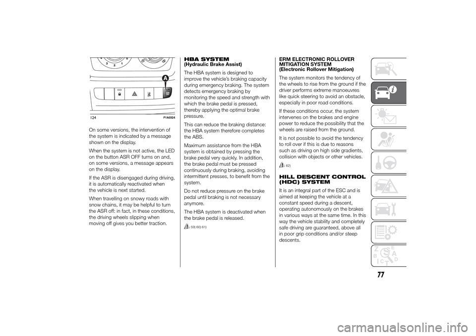
again by pressing the ASR OFF button
fig. 124.
57)
76
KNOW YOUR VEHICLE
Page 81 of 367
On some versions, the intervention of
the system is indicated by a message
shown on the display.
When the system is not active, the LED
on the button ASR OFF turns on and,
on some versions, a message appears
on the display.
If the ASR is disengaged during driving,
it is automatically reactivated when
the vehicle is next started.
When travelling on snowy roads with
snow chains, it may be helpful to turn
the ASR off: in fact, in these conditions,
the driving wheels slipping when
moving off gives you better traction.HBA SYSTEM
(Hydraulic Brake Assist)
The HBA system is designed to
improve the vehicle’s braking capacity
during emergency braking. The system
detects emergency braking by
monitoring the speed and strength with
which the brake pedal is pressed,
thereby applying the optimal brake
pressure.
This can reduce the braking distance:
the HBA system therefore completes
the ABS.
Maximum assistance from the HBA
system is obtained by pressing the
brake pedal very quickly. In addition,
the brake pedal must be pressed
continuously during braking, avoiding
intermittent presses, to benefit from the
system.
Do not reduce pressure on the brake
pedal until braking is not necessary
anymore.
The HBA system is deactivated when
the brake pedal is released.
59) 60) 61)
ERM ELECTRONIC ROLLOVER
MITIGATION SYSTEM
(Electronic Rollover Mitigation)
The system monitors the tendency of
the wheels to rise from the ground if the
driver performs extreme manoeuvres
like quick steering to avoid an obstacle,
especially in poor road conditions.
If these conditions occur, the system
intervenes on the brakes and engine
power to reduce the possibility that the
wheels are raised from the ground.
It is not possible to avoid the tendency
to roll over if this is due to reasons
such as driving on high side gradients,
collision with objects or other vehicles.
62)
HILL DESCENT CONTROL
(HDC) SYSTEM
It is an integral part of the ESC and is
aimed at keeping the vehicle at a
constant speed during a descent,
operating autonomously on the brakes
in various ways at the same time. In this
way the vehicle stability and completely
safe driving are guaranteed, above all
in poor grip conditions and/or steep
descents.
124
F1A0324
77