warning FIAT DUCATO 2014 Owner handbook (in English)
[x] Cancel search | Manufacturer: FIAT, Model Year: 2014, Model line: DUCATO, Model: FIAT DUCATO 2014Pages: 367, PDF Size: 20.39 MB
Page 176 of 367
PARKINGProceed as follows:
❒stop the engine and engage the
handbrake;
❒engage a gear (on a slope, engage
first gear if the car is facing uphill or
reverse if it is facing downhill) and
leave the wheels steered.
If the vehicle is parked on a steep
slope, it is advisable to block the
wheels with a wedge or stone.
Do not leave the key in the ignition as
this drains the battery. Always remove
the key when you leave the car.
126)
HANDBRAKE
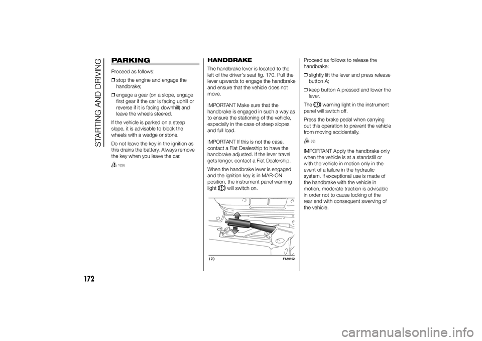
The handbrake lever is located to the
left of the driver's seat fig. 170. Pull the
lever upwards to engage the handbrake
and ensure that the vehicle does not
move.
IMPORTANT Make sure that the
handbrake is engaged in such a way as
to ensure the stationing of the vehicle,
especially in the case of steep slopes
and full load.
IMPORTANT If this is not the case,
contact a Fiat Dealership to have the
handbrake adjusted. If the lever travel
gets longer, contact a Fiat Dealership.
When the handbrake lever is engaged
and the ignition key is in MAR-ON
position, the instrument panel warning
light
will switch on.Proceed as follows to release the
handbrake:
❒slightly lift the lever and press release
button A;
❒keep button A pressed and lower the
lever.
The
warning light in the instrument
panel will switch off.
Press the brake pedal when carrying
out this operation to prevent the vehicle
from moving accidentally.
33)
IMPORTANT Apply the handbrake only
when the vehicle is at a standstill or
with the vehicle in motion only in the
event of a failure in the hydraulic
system. If exceptional use is made of
the handbrake with the vehicle in
motion, moderate traction is advisable
in order not to cause locking of the
rear end with consequent swerving of
the vehicle.
170
F1A0162
172
STARTING AND DRIVING
Page 177 of 367
WARNING
126) Never leave children
unattended in the vehicle. Always
remove the ignition key when
leaving the vehicle and take it out
with you.
IMPORTANT
33) If the vehicle is equipped with
self-levelling air suspension,
always check that there is
sufficient space above the roof
and around the vehicle when
parking. Indeed, the vehicle could
raise (or lower) automatically
depending on load or temperature
changes.
USING THE
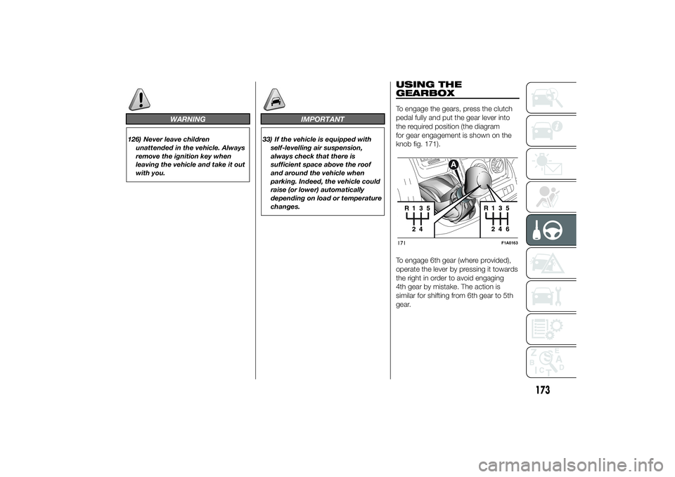
GEARBOXTo engage the gears, press the clutch
pedal fully and put the gear lever into
the required position (the diagram
for gear engagement is shown on the
knob fig. 171).
To engage 6th gear (where provided),
operate the lever by pressing it towards
the right in order to avoid engaging
4th gear by mistake. The action is
similar for shifting from 6th gear to 5th
gear.171
F1A0163
173
Page 178 of 367
IMPORTANT Reverse may only be
engaged when the vehicle is at a
standstill. With the engine running, wait
for at least 2 seconds with the clutch
pedal fully pressed before engaging
reverse to prevent damage to the gears
and grating.
To engage reverse R from neutral,
proceed as follows: raise sliding ring A
under the knob and at the same time
move the gear lever to the left and then
forwards.
127)34)
WARNING
127) Depress the clutch pedal fully
to change gear correctly. It is
therefore essential that there is
nothing under the pedals: make
sure the mats are lying flat and do
not get in the way of the pedals.
IMPORTANT
34) Do not drive with your hand
resting on the gear lever as the
force exerted, even if slight, could
lead over time to premature wear
of the internal gearbox
components. The clutch pedal
should be used only for gear
changes. Do not drive with your
foot resting on the clutch pedal,
however lightly. For versions/
markets where provided, the
electronic clutch pedal control
could cut in, interpreting the
incorrect driving style as a fault.
174
STARTING AND DRIVING
Page 179 of 367
LOADING ADVICEThe Fiat Ducato version used by you
has been designed and type approved
on the basis of certain maximum
weights (see "Weights" table in the
"Technical Data" chapter): kerb weight,
payload, total weight, maximum weight
on front axle, maximum weight on
rear axle, towable weight.
IMPORTANT The maximum permitted
load on the floor fastenings is 500
kg; the maximum permitted load on the
side panel is 150 kg.
IMPORTANT For versions with right and
left side flaps, it is advisable to
reposition the release lever in the closed
position before lowering the sides.
35)128) 129) 130)
In addition to these general
precautions, some simple precautions
can improve driving safety, travelling
comfort and vehicle durability:
❒distribute the load evenly over the
platform: if it is necessary to
concentrate it in a single area,
choose an area mid-way between
both axles;❒lastly, remember that the vehicle’s
dynamic behaviour is affected by
the weight transported: in particular,
the stopping distances are longer,
especially at high speed.
IMPORTANT
35) Each of these must be strictly
observed and MUST NEVER BE
EXCEEDED in any case. In
particular, ensure that you never
exceed the maximum permitted
weights on the front and rear
axles when arranging the load on
the vehicle (particularly if the
vehicle is equipped with a specific
trim level).
WARNING
128) Irregular trajectories and abrupt
braking may cause sudden
movements of the load with
consequent situations of hazard
for the driver and passengers:
before setting off, secure the load
tightly using the appropriate
hooks on the floor and use steel
cables, ropes or chains strong
enough to hold the items to be
secured.
129) If a vehicle is parked on a very
steep gradient or with a side
gradient, opening the rear door or
side door could cause any
unsecured items to emerge
suddenly.
130) If you wish to carry a reserve of
petrol in a can, observe the legal
restrictions and only use a can
that is type-approved and
properly secured to the load
anchorage eyebolts. Anyway, by
doing so, you increase the risk
of fire in the event of an accident
with your vehicle.
175
Page 182 of 367
TOWING TRAILERSIMPORTANT
INFORMATION
The vehicle must be provided with a
type-approved tow hook and adequate
electrical system to tow caravans or
trailers. Installation should be carried
out by specialised personnel who
will issue the required papers for
travelling on roads.
Install any specific and/or additional
door mirrors as specified by the
Highway Code.
Remember that when towing a trailer,
steep hills are harder to climb, the
braking spaces increase and overtaking
takes longer depending on the overall
weight.
Engage a low gear when driving
downhill, rather than constantly using
the brake.
The weight of the trailer on the vehicle
tow hook will reduce the loading
capacity of the vehicle by the same
amount. Consider the weight of the
trailer fully laden, including accessories
and luggage, to make sure you do
not exceed the maximum towable
weight (shown on the vehicle
registration document).Do not exceed the speed limits specific
to each country you are driving in, in
the case of vehicles towing trailers.
In any case, the top speed must not
exceed 100 km/h.
You are advised to fit a suitable
stabiliser to the trailer drawbar.
In the vehicles equipped with parking
sensors, after fitting the tow hook
malfunctioning warnings may be
displayed, as some parts (tow bar, ball
tow hook) may be within the sensor
detection range. In this case the
detection range must be adjusted or
the parking assistance function must be
deactivated.
131) 132)
INSTALLING THE TOW
HOOK
The towing device should be fastened
to the body by specialised personnel
according to any additional and/or
integrative information supplied by the
Manufacturer of the device.
The towing device must meet current
regulations with reference to Directive
94/20/EC and subsequent
amendments.
For any version the towing device used
must match the towable weight of the
vehicle on which it is to be installed.
For the electric connection a standard
connector should be used which is
generally placed on a special bracket
normally fastened to the towing device,
and a special ECU for external trailer
light control must be installed on the
vehicle. For the electrical connection, 7
or 13 pin 12 V DC connections are to
be used (CUNA/UNI and ISO/DIN
Standards). Follow the instructions
provided by the vehicle manufacturer
and/or the tow hitch manufacturer.
An electric brake (or electric winch)
should be supplied directly by the
battery through a cable with a cross
section of no less than 2.5 mm
2.
178
STARTING AND DRIVING
Page 184 of 367
WARNING
131) The ABS device with which the
vehicle may be equipped will not
control the braking system of
the trailer. Particular caution is
required on slippery roads.
132) Never modify the braking
system of the vehicle to control
the trailer brake. The trailer
braking system must be fully
independent from the hydraulic
system of the vehicle.
133) After fitting, fixing screw holes
must be sealed to prevent an
exhaust gas inlet.
134) After fitting, fixing screw holes
must be sealed to prevent an
exhaust gas inlet.
180
STARTING AND DRIVING
Page 190 of 367
SNOW TYRESA Fiat Dealership will be happy to
provide advice concerning the most
suitable type of tyre for the customer's
requirements.
The performance of these tyres is
considerably reduced when the tread
depth is less than 4 mm. Replace them
in this case.
Due to the specific characteristics of
snow tyres, in normal weather
conditions or on long motorway
journeys, the performance of these
tyres is lower than that of standard
tyres. Their usage should therefore be
restricted in accordance with their
type approval.IMPORTANT When using snow tyres
with a maximum speed index below the
one that can be reached by the vehicle
(increased by 5%), place a notice in
the passenger compartment, plainly in
view, which states the maximum speed
allowed by the snow tyres (as per EC
Directive).
All four tyres should be the same (brand
and track) to ensure greater safety
when driving and braking as well as a
good manoeuvrability.
Remember that you should not change
the rotation direction of the tyres.
135)
WARNING
135) The maximum speed for snow
tyres marked "Q" is 160 km/h,
while it is 190 km/h for "T" tyres
and 210 km/h for "H" tyres. You
should, however, always comply
with the speed limits of the
highway code.
186
STARTING AND DRIVING
Page 194 of 367

STARTING THE
ENGINEGo to a Fiat Dealership immediately if
warning light
stays on constantly on
the instrument panel.
JUMP STARTING
If the battery is flat, it is possible to start
the engine using an auxiliary battery
with the same capacity or a little higher
than the flat one.
It is advisable to contact a Fiat
Dealership to check/replace the battery.
136)
Proceed as follows to start the vehicle:
❒raise the flap A fig. 177 to gain
access to the positive battery
terminal.❒connect the positive terminals (sign +
near the terminal) of the two batteries
with a jump lead;
❒use a second cable to connect the
negative terminal (–) of the auxiliary
battery to the earth point as shown in
fig. 178;
❒start the engine;
❒when the engine has been started,
remove the cables reversing the
order above.
If after a few attempts the engine does
not start, do not persist but contact
the nearest Fiat Dealership.IMPORTANT Do not directly connect
the negative terminals of the two
batteries: sparks could ignite explosive
gas released from the battery. If the
auxiliary battery is installed on another
vehicle, avoid any metal parts on the
latter and the vehicle with the flat
battery from accidentally coming into
contact.177
F1A0351
178
F1A0352
190
IN AN EMERGENCY
Page 195 of 367
BUMP STARTING
Never bump start the engine by
pushing, towing or driving downhill.
This could cause fuel to flow into the
catalytic converter and damage it
beyond repair.
WARNING
136) This procedure must be
performed by qualified personnel
as incorrect actions may cause
high-intensity electrical discharge.
Furthermore, battery fluid is
poisonous and corrosive: avoid
contact with skin and eyes. Keep
naked flames and lighted
cigarettes away from the battery
and do not cause sparks.
REPLACING A
WHEELGENERAL
INSTRUCTIONS
Wheel replacement and correct use of
the jack and spare wheel (for
versions/markets, where provided) call
for some precautions, which are listed
below.
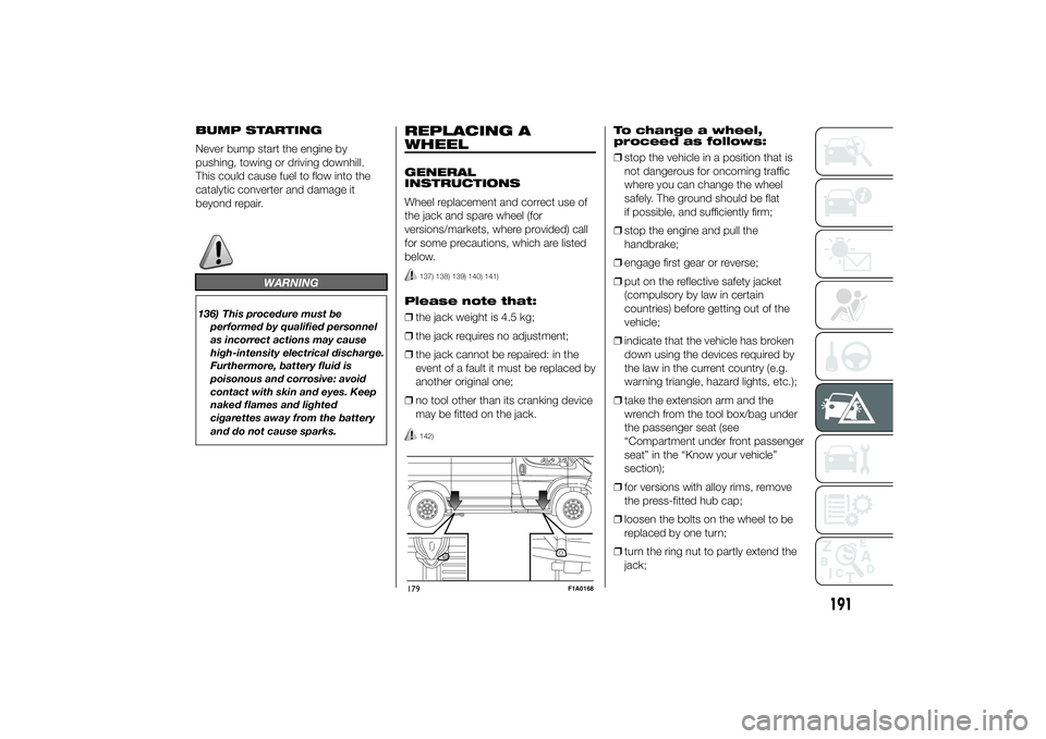
137) 138) 139) 140) 141)
Please note that:
❒the jack weight is 4.5 kg;
❒the jack requires no adjustment;
❒the jack cannot be repaired: in the
event of a fault it must be replaced by
another original one;
❒no tool other than its cranking device
may be fitted on the jack.
142)
To change a wheel,
proceed as follows:
❒stop the vehicle in a position that is
not dangerous for oncoming traffic
where you can change the wheel
safely. The ground should be flat
if possible, and sufficiently firm;
❒stop the engine and pull the
handbrake;
❒engage first gear or reverse;
❒put on the reflective safety jacket
(compulsory by law in certain
countries) before getting out of the
vehicle;
❒indicate that the vehicle has broken
down using the devices required by
the law in the current country (e.g.
warning triangle, hazard lights, etc.);
❒take the extension arm and the
wrench from the tool box/bag under
the passenger seat (see
“Compartment under front passenger
seat” in the “Know your vehicle”
section);
❒for versions with alloy rims, remove
the press-fitted hub cap;
❒loosen the bolts on the wheel to be
replaced by one turn;
❒turn the ring nut to partly extend the
jack;
179
F1A0168
191
Page 198 of 367
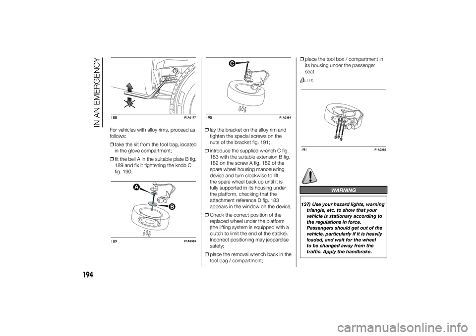
For vehicles with alloy rims, proceed as
follows:
❒take the kit from the tool bag, located
in the glove compartment;
❒fit the bell A in the suitable plate B fig.
189 and fix it tightening the knob C
fig. 190;❒lay the bracket on the alloy rim and
tighten the special screws on the
nuts of the bracket fig. 191;
❒introduce the supplied wrench C fig.
183 with the suitable extension B fig.
182 on the screw A fig. 182 of the
spare wheel housing manoeuvring
device and turn clockwise to lift
the spare wheel back up until it is
fully supported in its housing under
the platform, checking that the
attachment reference D fig. 183
appears in the window on the device;
❒Check the correct position of the
replaced wheel under the platform
(the lifting system is equipped with a
clutch to limit the end of the stroke).
Incorrect positioning may jeopardise
safety;
❒place the removal wrench back in the
tool bag / compartment;❒place the tool box / compartment in
its housing under the passenger
seat.
147)
WARNING
137) Use your hazard lights, warning
triangle, etc. to show that your
vehicle is stationary according to
the regulations in force.
Passengers should get out of the
vehicle, particularly if it is heavily
loaded, and wait for the wheel
to be changed away from the
traffic. Apply the handbrake.
188
F1A0177
189
F1A0383
190
F1A0384
191
F1A0385
194
IN AN EMERGENCY