ignition FIAT DUCATO 2015 3.G User Guide
[x] Cancel search | Manufacturer: FIAT, Model Year: 2015, Model line: DUCATO, Model: FIAT DUCATO 2015 3.GPages: 387, PDF Size: 20.76 MB
Page 54 of 387
DIRECTION INDICATORS
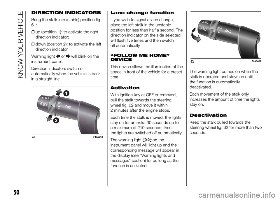
Bring the stalk into (stable) position fig.
61:
❒up (position 1): to activate the right
direction indicator;
❒down (position 2): to activate the left
direction indicator.
Warning light
orwill blink on the
instrument panel.
Direction indicators switch off
automatically when the vehicle is back
in a straight line.Lane change function
If you wish to signal a lane change,
place the left stalk in the unstable
position for less than half a second. The
direction indicator on the side selected
will flash five times and then switch
off automatically.
“FOLLOW ME HOME”
DEVICE
This device allows the illumination of the
space in front of the vehicle for a preset
time.
Activation
With ignition key at OFF or removed,
pull the stalk towards the steering
wheel fig. 62 and move it within
2 minutes after the engine stops.
Each time the stalk is moved, the lights
stay on for an extra 30 seconds up to
a maximum of 210 seconds; then
the lights are switched off automatically.
The warning light
on the
instrument panel will light up and the
corresponding message will appear in
the display (see “Warning lights and
messages” section) for as long as the
function is activated.The warning light comes on when the
stalk is operated and stays on until
the function is automatically
deactivated.
Each movement of the stalk only
increases the amount of time the lights
stay on.
Deactivation
Keep the stalk pulled towards the
steering wheel fig. 62 for more than two
seconds.61F1A0068
62F1A0069
50
KNOW YOUR VEHICLE
Page 56 of 387
WINDOW CLEANING
IN BRIEF
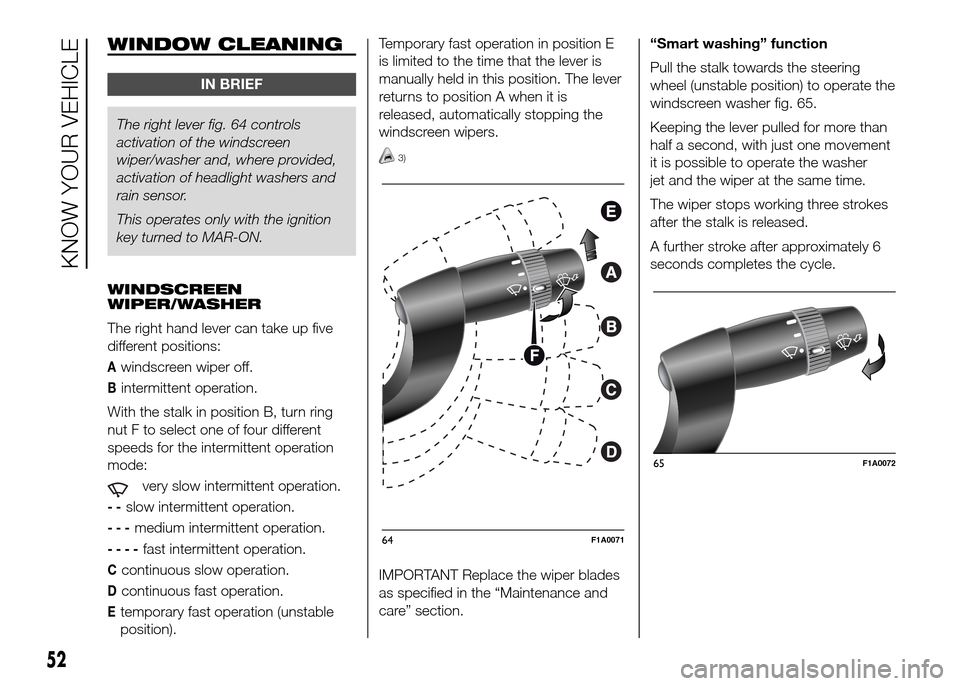
The right lever fig. 64 controls
activationof the windscreen
wiper/washer and, where provided,
activation of headlight washers and
rain sensor.
This operates only with the ignition
key turned to MAR-ON.
WINDSCREEN
WIPER/WASHER
The right hand lever can take up five
different positions:
Awindscreen wiper off.
Bintermittent operation.
With the stalk in position B, turn ring
nut F to select one of four different
speeds for the intermittent operation
mode:
very slow intermittent operation.
--slow intermittent operation.
---medium intermittent operation.
----fast intermittent operation.
Ccontinuous slow operation.
Dcontinuous fast operation.
Etemporary fast operation (unstable
position).Temporary fast operation in position E
is limited to the time that the lever is
manually held in this position. The lever
returns to position A when it is
released, automatically stopping the
windscreen wipers.
3)
IMPORTANT Replace the wiper blades
as specified in the “Maintenance and
care” section.“Smart washing” function
Pull the stalk towards the steering
wheel (unstable position) to operate the
windscreen washer fig. 65.
Keeping the lever pulled for more than
half a second, with just one movement
it is possible to operate the washer
jet and the wiper at the same time.
The wiper stops working three strokes
after the stalk is released.
A further stroke after approximately 6
seconds completes the cycle.
64F1A0071
65F1A0072
52
KNOW YOUR VEHICLE
Page 57 of 387
RAIN SENSOR
(for versions/markets, where provided)
The rain sensor is located behind the
rear view mirror in contact with the
windscreen and has the purpose of
automatically adjusting the frequency of
the windscreen wiper strokes
depending on the intensity of the rain
during intermittent operation.
IMPORTANT Keep the glass in the
sensor area clean.
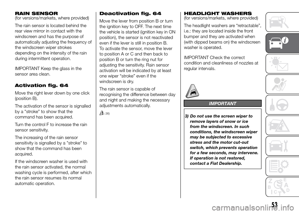
Activation fig. 64
Move the right lever down by one click
(position B).
The activation of the sensor is signalled
by a "stroke" to show that the
command has been acquired.
Turn the control F to increase the rain
sensor sensitivity.
The increasing of the rain sensor
sensitivity is signalled by a "stroke" to
show that the command has been
acquired.
If the windscreen washer is used with
the rain sensor activated, the normal
washing cycle is performed, after which
the rain sensor resumes its normal
automatic operation.Deactivation fig. 64
Move the lever from position B or turn
the ignition key to OFF. The next time
the vehicle is started (ignition key in ON
position), the sensor is not reactivated
even if the lever is still in position B.
To activate the sensor, move the lever
to position A or C and then back to
position B or turn the ring nut for
adjusting the sensitivity. Rain sensor
activation will be indicated by at least
one wiper “stroke” even if the
windscreen is dry.
The rain sensor is capable of
recognising the difference between day
and night and making the necessary
adjustments automatically.
26)
HEADLIGHT WASHERS
(for versions/markets, where provided)
The headlight washers are “retractable”,
i.e.: they are located inside the front
bumper and they are activated when
(with dipped beams on) the windscreen
washer is operated.
IMPORTANT Check the correct
condition and cleanliness of nozzles at
regular intervals.
IMPORTANT
3) Do not use the screen wiper to
remove layers of snow or ice
from the windscreen. In such
conditions, the windscreen wiper
may be subjected to excessive
stress and the motor cut-out
switch, which prevents operation
for a few seconds, may intervene.
If operation is not restored,
contact a Fiat Dealership.
53
Page 62 of 387
ROOF LIGHTS
FRONT ROOF LIGHT WITH
SPOT LIGHTS
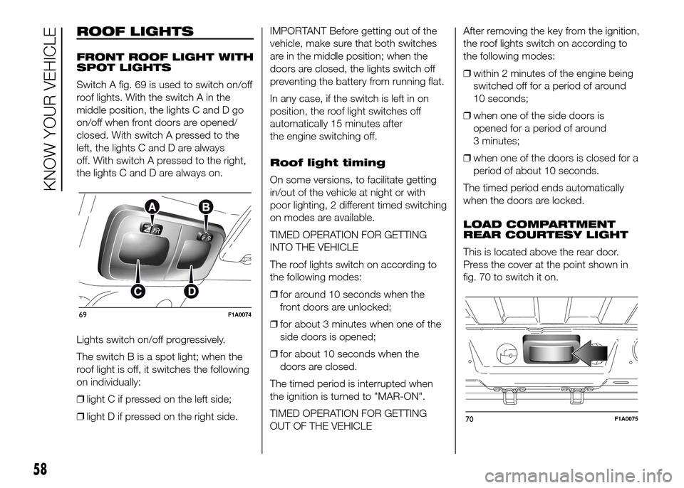
Switch A fig. 69 is used to switch on/off
roof lights. With the switch A in the
middle position, the lights C and D go
on/off when front doors are opened/
closed. With switch A pressed to the
left, the lights C and D are always
off. With switch A pressed to the right,
the lights C and D are always on.
Lights switch on/off progressively.
The switch B is a spot light; when the
roof light is off, it switches the following
on individually:
❒light C if pressed on the left side;
❒light D if pressed on the right side.IMPORTANT Before getting out of the
vehicle, make sure that both switches
are in the middle position; when the
doors are closed, the lights switch off
preventing the battery from running flat.
In any case, if the switch is left in on
position, the roof light switches off
automatically 15 minutes after
the engine switching off.
Roof light timing
On some versions, to facilitate getting
in/out of the vehicle at night or with
poor lighting, 2 different timed switching
on modes are available.
TIMED OPERATION FOR GETTING
INTO THE VEHICLE
The roof lights switch on according to
the following modes:
❒for around 10 seconds when the
front doors are unlocked;
❒for about 3 minutes when one of the
side doors is opened;
❒for about 10 seconds when the
doors are closed.
The timed period is interrupted when
the ignition is turned to "MAR-ON".
TIMED OPERATION FOR GETTING
OUT OF THE VEHICLEAfter removing the key from the ignition,
the roof lights switch on according to
the following modes:
❒within 2 minutes of the engine being
switched off for a period of around
10 seconds;
❒when one of the side doors is
opened for a period of around
3 minutes;
❒when one of the doors is closed for a
period of about 10 seconds.
The timed period ends automatically
when the doors are locked.
LOAD COMPARTMENT
REAR COURTESY LIGHT
This is located above the rear door.
Press the cover at the point shown in
fig. 70 to switch it on.
69F1A0074
70F1A0075
58
KNOW YOUR VEHICLE
Page 63 of 387
LOAD COMPARTMENT
SIDE COURTESY LIGHT
(for versions/markets, where provided)
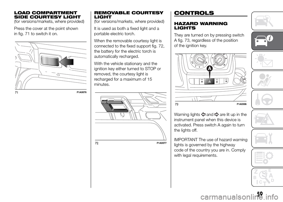
Press the cover at the point shown
in fig. 71 to switch it on.REMOVABLE COURTESY
LIGHT
(for versions/markets, where provided)
It is used as both a fixed light and a
portable electric torch.
When the removable courtesy light is
connected to the fixed support fig. 72,
the battery for the electric torch is
automatically recharged.
With the vehicle stationary and the
ignition key either turned to STOP or
removed, the courtesy light is
recharged for a maximum of 15
minutes.CONTROLS
HAZARD WARNING
LIGHTS
They are turned on by pressing switch
A fig. 73, regardless of the position
of the ignition key.
Warning lights
andare lit up in the
instrument panel when this device is
activated. Press switch A again to turn
the lights off.
IMPORTANT The use of hazard warning
lights is governed by the highway
code of the country you are in. Comply
with legal requirements.
71F1A0076
72F1A0077
73F1A0306
59
Page 64 of 387
Emergency braking
(for versions/markets, where provided)
In the event of emergency braking
the hazard warning lights come on
automatically, as do the
and
warning lights in the panel. The
function switches off automatically
when the nature of the braking
changes. This function complies with
the relevant legislation currently in force.
FOG LIGHTS
(for versions/markets, where provided)
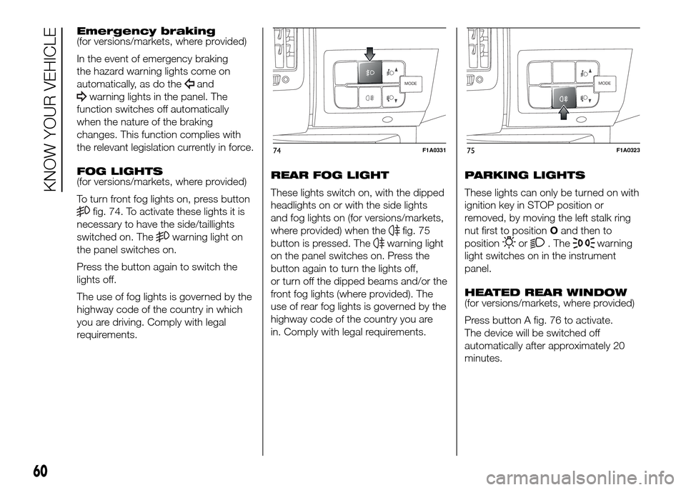
To turn front fog lights on, press button
fig. 74. To activate these lights it is
necessary to have the side/taillights
switched on. The
warning light on
the panel switches on.
Press the button again to switch the
lights off.
The use of fog lights is governed by the
highway code of the country in which
you are driving. Comply with legal
requirements.REAR FOG LIGHT
These lights switch on, with the dipped
headlights on or with the side lights
and fog lights on (for versions/markets,
where provided) when thefig. 75
button is pressed. The
warning light
on the panel switches on. Press the
button again to turn the lights off,
or turn off the dipped beams and/or the
front fog lights (where provided). The
use of rear fog lights is governed by the
highway code of the country you are
in. Comply with legal requirements.PARKING LIGHTS
These lights can only be turned on with
ignition key in STOP position or
removed, by moving the left stalk ring
nut first to positionOand then to
positionor. Thewarning
light switches on in the instrument
panel.
HEATED REAR WINDOW
(for versions/markets, where provided)
Press button A fig. 76 to activate.
The device will be switched off
automatically after approximately 20
minutes.
MODE
74F1A0331
MODE
75F1A0323
60
KNOW YOUR VEHICLE
Page 65 of 387
BATTERY
DISCONNECTION
FUNCTION
(DISCONNECTOR)
(for versions/markets, where provided)
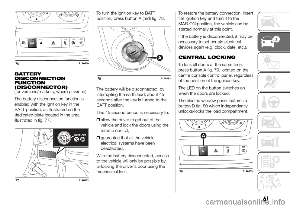
The battery disconnection function is
enabled with the ignition key in the
BATT position, as illustrated on the
dedicated plate located in the area
illustrated in fig. 77.To turn the ignition key to BATT
position, press button A (red) fig. 78.
The battery will be disconnected, by
interrupting the earth lead, about 45
seconds after the key is turned to the
BATT position.
This 45 second period is necessary to:
❒allow the driver to get out of the
vehicle and lock the doors using the
remote control;
❒guarantee that all the vehicle
electrical systems have been
deactivated.
With the battery disconnected, access
to the vehicle will only be possible by
unlocking the driver's door using the
mechanical lock.To restore the battery connection, insert
the ignition key and turn it to the
MAR-ON position, the vehicle can be
started normally at this point.
If the battery is disconnected, it may be
necessary to set certain electrical
devices again (e.g. clock, date, etc.).
CENTRAL LOCKING
To lock all doors at the same time,
press button A fig. 79, located on the
centre console control panel, regardless
of the position of the ignition key.
The LED on the button switches on
when the doors are locked.
The electric window panel features a
button D fig. 80 which independently
unlocks/locks the load compartment.
76F1A0330
77F1A0082
78F1A0083
79F1A0303
61
Page 66 of 387
.
FUEL CUT-OFF
SWITCH
The vehicle is fitted with a safety switch
that, in the event of a crash, comes
into operation by cutting off the fuel
supply and turning off the engine as a
consequence.
When the inertia switch cuts in, it cuts
off the fuel supply and also activates
the hazard warning lights, side lights
and courtesy lights while releasing
all the doors and displaying the relevant
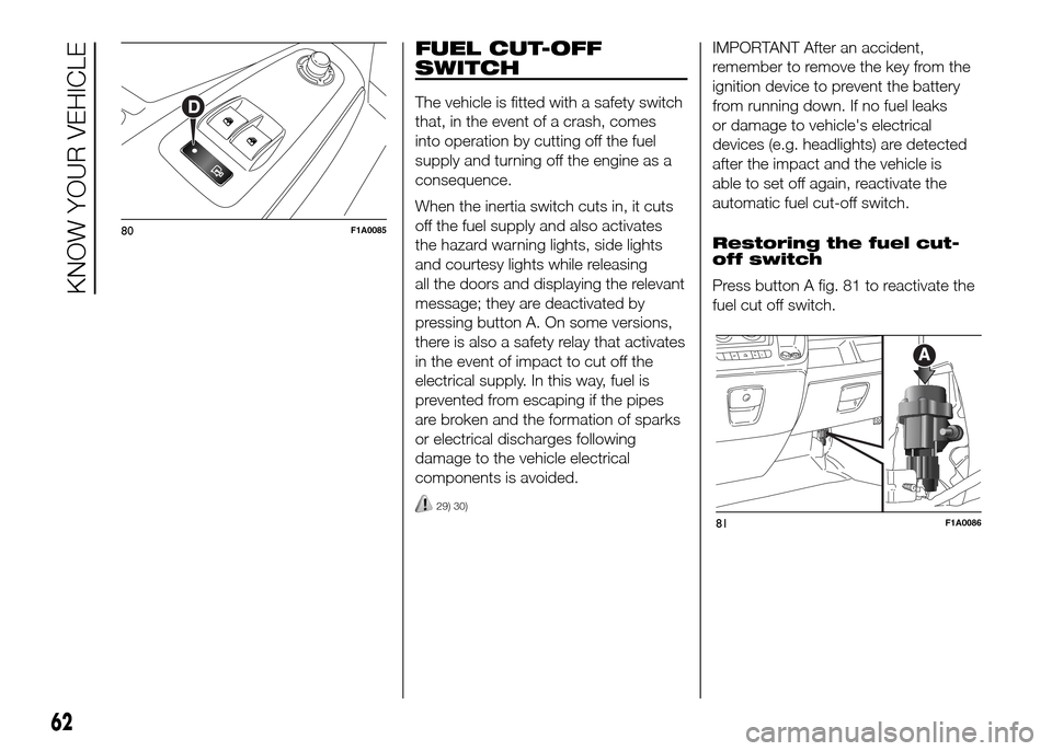
message; they are deactivated by
pressing button A. On some versions,
there is also a safety relay that activates
in the event of impact to cut off the
electrical supply. In this way, fuel is
prevented from escaping if the pipes
are broken and the formation of sparks
or electrical discharges following
damage to the vehicle electrical
components is avoided.
29) 30)
IMPORTANT After an accident,
remember to remove the key from the
ignition device to prevent the battery
from running down. If no fuel leaks
or damage to vehicle's electrical
devices (e.g. headlights) are detected
after the impact and the vehicle is
able to set off again, reactivate the
automatic fuel cut-off switch.
Restoring the fuel cut-
off switch
Press button A fig. 81 to reactivate the
fuel cut off switch.
80F1A0085
81F1A0086
62
KNOW YOUR VEHICLE
Page 69 of 387
COMPARTMENT
BENEATH PASSENGER
SIDE FRONT SEAT
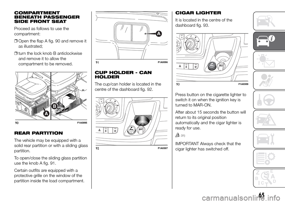
Proceed as follows to use the
compartment:
❒Open the flap A fig. 90 and remove it
as illustrated;
❒turn the lock knob B anticlockwise
and remove it to allow the
compartment to be removed.
REAR PARTITION
The vehicle may be equipped with a
solid rear partition or with a sliding glass
partition.
To open/close the sliding glass partition
use the knob A fig. 91.
Certain outfits are equipped with a
protective grille on the window of the
partition inside the load compartment.CUP HOLDER - CAN
HOLDER
The cup/can holder is located in the
centre of the dashboard fig. 92.CIGAR LIGHTER
It is located in the centre of the
dashboard fig. 93.
Press button on the cigarette lighter to
switch it on when the ignition key is
turned to MAR-ON.
After about 15 seconds the button will
return to its original position
automatically and the cigar lighter is
ready for use.
31)
IMPORTANT Always check that the
cigar lighter has switched off.
90F1A0095
91F1A0096
92F1A0307
93F1A0309
65
Page 77 of 387
Device activation
The dead lock device is automatically
activated on every door with two short
presses on the button
on the key
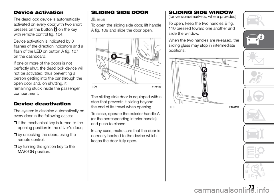
with remote control fig. 104.
Device activation is indicated by 3
flashes of the direction indicators and a
flash of the LED on button A fig. 107
on the dashboard.
If one or more of the doors is not
perfectly shut, the dead lock device will
not be activated, thus preventing a
person getting into the car through the
open door and, on shutting, it,
remaining stuck inside the passenger
compartment.
Device deactivation
The system is disabled automatically on
every door in the following cases:
❒if the mechanical key is turned to the
opening position in the driver's door;
❒by unlocking the doors using the
remote control;
❒by turning the ignition key to the
MAR-ON position.SLIDING SIDE DOOR
35) 36)
To open the sliding side door, lift handle
A fig. 109 and slide the door open.
The sliding side door is equipped with a
stop that prevents it sliding beyond
the end of its travel when opening.
To close, operate the exterior handle A
(or the corresponding interior handle)
and push to closed.
In any case, make sure that the door is
correctly hooked to the device which
keeps the door fully open.SLIDING SIDE WINDOW
(for versions/markets, where provided)
To open, keep the two handles B fig.
110 pressed toward one another and
slide the window.
When the two handles are released, the
sliding glass may stop in intermediate
positions.
109F1A0117
110F1A0118
73