ignition FIAT DUCATO 2015 3.G Owner's Manual
[x] Cancel search | Manufacturer: FIAT, Model Year: 2015, Model line: DUCATO, Model: FIAT DUCATO 2015 3.GPages: 387, PDF Size: 20.76 MB
Page 81 of 387
ELECTRIC WINDOWS
ELECTRIC
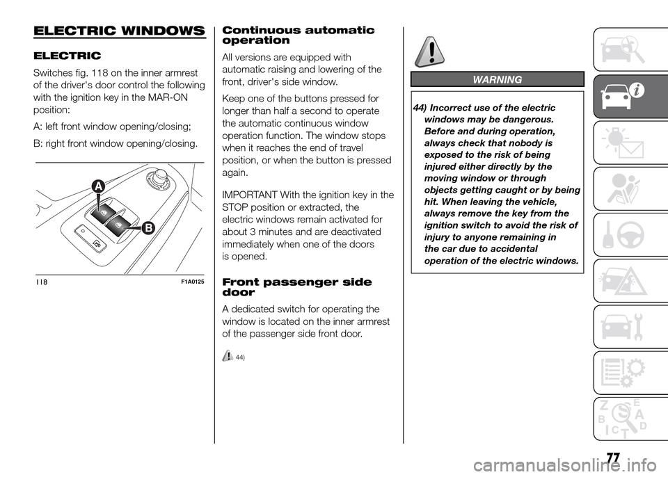
Switches fig. 118 on the inner armrest
of the driver's door control the following
with the ignition key in the MAR-ON
position:
A: left front window opening/closing;
B: right front window opening/closing.Continuous automatic
operation
All versions are equipped with
automatic raising and lowering of the
front, driver's side window.
Keep one of the buttons pressed for
longer than half a second to operate
the automatic continuous window
operation function. The window stops
when it reaches the end of travel
position, or when the button is pressed
again.
IMPORTANT With the ignition key in the
STOP position or extracted, the
electric windows remain activated for
about 3 minutes and are deactivated
immediately when one of the doors
is opened.
Front passenger side
door
A dedicated switch for operating the
window is located on the inner armrest
of the passenger side front door.
44)
WARNING
44) Incorrect use of the electric
windows may be dangerous.
Before and during operation,
always check that nobody is
exposed to the risk of being
injured either directly by the
moving window or through
objects getting caught or by being
hit. When leaving the vehicle,
always remove the key from the
ignition switch to avoid the risk of
injury to anyone remaining in
the car due to accidental
operation of the electric windows.
118F1A0125
77
Page 84 of 387
HEADLIGHTS
LIGHT BEAM ALIGNMENT
The correct alignment of the headlights
is essential for the comfort and safety
of the driver and other road users.
To ensure the best visibility when
travelling with the headlights on, the
headlight alignment must be correct.
Contact a Fiat Dealership to have
the headlights checked and adjusted.
HEADLIGHT ALIGNMENT
CORRECTOR
This device works with the ignition key
in the MAR-ON position and the dipped
beam headlights on.
The vehicle tilts backwards when it is
laden, raising the beam.
The beams must therefore be realigned
in this case.
Headlight alignment
adjustment
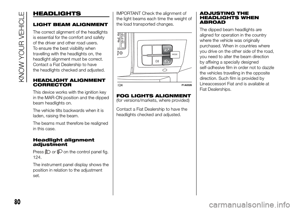
Press
oron the control panel fig.
124.
The instrument panel display shows the
position in relation to the adjustment
set.IMPORTANT Check the alignment of
the light beams each time the weight of
the load transported changes.
FOG LIGHTS ALIGNMENT
(for versions/markets, where provided)
Contact a Fiat Dealership to have the
headlights checked and adjusted.ADJUSTING THE
HEADLIGHTS WHEN
ABROAD
The dipped beam headlights are
aligned for operation in the country
where the vehicle was originally
purchased. When in countries where
you drive on the other side of the road,
you need to alter the beam direction
by affixing a specially designed
self-adhesive film in order not to dazzle
the vehicles travelling in the opposite
direction. Such film is provided by
Lineaccessori Fiat and is available at
Fiat Dealerships.
MODEMODE
124F1A0326
80
KNOW YOUR VEHICLE
Page 93 of 387
TPMS operation faults
The system fault is indicated by
warning light
which first flashes for
75 seconds and then stays on steadily.
This can occur in any of the following
situations:
❒interference caused by electronic
devices or radio frequency emissions
similar to those of the TPM sensors.
❒Application of tinted films which
interfere with the signals of the radio
waves.
❒Presence of snow or ice on the
wheels or the wheel arches.
❒Use of snow chains.
❒Use of wheels/tyres not equipped
with TPM sensors.
❒The space-saver wheel is not
equipped with the tyre pressure
control sensor. Therefore, the tyre
pressure is not controlled by the
system.
❒If the space-saver wheel replaces a
tyre with a pressure lower than the
insufficient pressure limit, an acoustic
signal will be emitted and the warning
light
will switch on at the next
ignition cycle.❒When the original tyre is repaired or
replaced and it is mounted back on
the vehicle to replace the space-
saver wheel, the TPMS will update
automatically and the warning light
will switch off, provided that the
pressure of none of the four tyres is
below the insufficient pressure limit.
You may need to drive the vehicle for
about 20 minutes at a speed higher
than 20 km/h to allow the TPMS
to receive this information.IMPORTANT
INFORMATION
WARNING
69) The TPMS is optimised for the
original tyres and wheels
provided. TPMS pressures and
alerts have been defined
according to the size of the tyres
mounted on the vehicle. Using
equipment with different size,
type or kind may cause irregular
system operation or sensor
damage. Non-original spare
wheels can damage the sensor.
Do not use tyre sealant or
balancing weights if the vehicle is
equipped with TPMS as these
may damage the sensors.
70) If the system signals a pressure
decrease on a specific tyre, it is
recommended to check the
pressure on all four tyres.
71) TPMS does not relieve the driver
from the obligation to check the
tyre pressure every month; it is
not even to be considered a
replacing system for maintenance
or a safety system.
89
Page 108 of 387
"ENERGY SAVING"
FUNCTION
(for versions/markets, where provided)
If, after the engine has been
automatically restarted, the driver does
not take any action for a period of
about 3 minutes, the Start&Stop
system will definitively stop the engine
to avoid fuel consumption. The engine
can only be started using the key in
such cases.
NoteIn any case, it is possible to keep
the engine running by deactivating
the Start&Stop system.
IRREGULAR OPERATION
In the event of malfunction, the
Start&Stop system is deactivated. The
driver is informed about the fault
through the switching on of the
icon
together with a message on the
display. In this case, contact a Fiat
Dealership.VEHICLE INACTIVITY
In the event of vehicle inactivity, special
attention must be paid to the
disconnection of the battery power
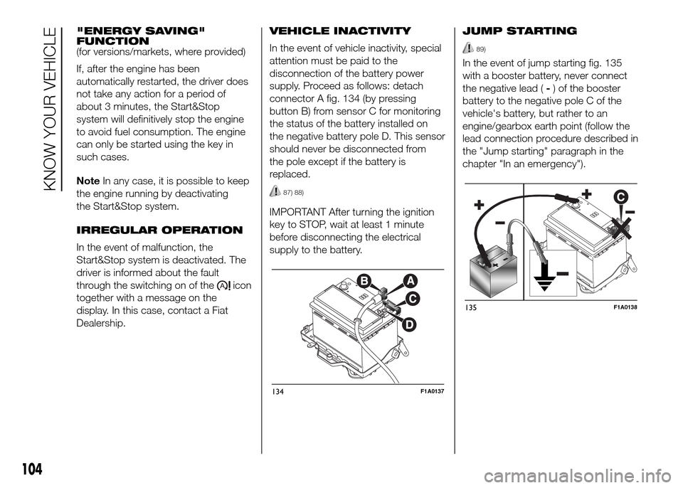
supply. Proceed as follows: detach
connector A fig. 134 (by pressing
button B) from sensor C for monitoring
the status of the battery installed on
the negative battery pole D. This sensor
should never be disconnected from
the pole except if the battery is
replaced.
87) 88)
IMPORTANT After turning the ignition
key to STOP, wait at least 1 minute
before disconnecting the electrical
supply to the battery.JUMP STARTING
89)
In the event of jump starting fig. 135
with a booster battery, never connect
the negative lead (-) of the booster
battery to the negative pole C of the
vehicle's battery, but rather to an
engine/gearbox earth point (follow the
lead connection procedure described in
the "Jump starting" paragraph in the
chapter "In an emergency").
134F1A0137
135F1A0138
104
KNOW YOUR VEHICLE
Page 113 of 387
REFUELLING THE
VEHICLE
IN BRIEF
Refuel the vehicle exclusively with
dieselfor motor vehicles in
compliance with European
specification EN590.
Stop the engine before refuelling.
OPERATION AT LOW
TEMPERATURES
If the outside temperature is very low,
diesel thickens due to the formation
of paraffin clots with consequent
defective operation of the fuel supply
system.
In order to avoid these problems,
different types of diesel are distributed
according to the season: summer type,
winter type and arctic type (cold/
mountain areas). If refuelling with diesel
fuel whose specifications are not
suitable for the current temperature, it is
advisable to mix TUTELA DIESEL ART
additive in the proportions shown on
the container. Pour the additive into the
tank before the diesel fuel.When using or parking the vehicle for a
long time in the mountains or cold
areas, it is advisable to refuel using
locally available diesel fuel.
In this case, it is also advisable to keep
the tank over 50% full.
19)
FILLING THE TANK
To fill the tank completely, top-up twice
after the first click of the fuel supply
gun. Further top-ups could cause faults
in the fuel supply system.
FUEL TANK CAP
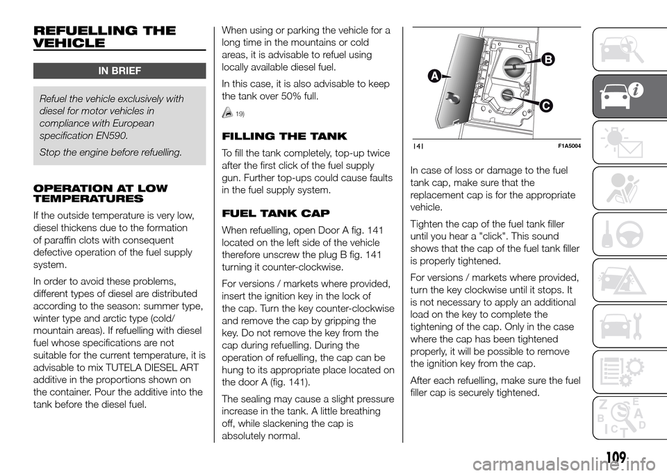
When refuelling, open Door A fig. 141
located on the left side of the vehicle
therefore unscrew the plug B fig. 141
turning it counter-clockwise.
For versions / markets where provided,
insert the ignition key in the lock of
the cap. Turn the key counter-clockwise
and remove the cap by gripping the
key. Do not remove the key from the
cap during refuelling. During the
operation of refuelling, the cap can be
hung to its appropriate place located on
the door A (fig. 141).
The sealing may cause a slight pressure
increase in the tank. A little breathing
off, while slackening the cap is
absolutely normal.In case of loss or damage to the fuel
tank cap, make sure that the
replacement cap is for the appropriate
vehicle.
Tighten the cap of the fuel tank filler
until you hear a "click". This sound
shows that the cap of the fuel tank filler
is properly tightened.
For versions / markets where provided,
turn the key clockwise until it stops. It
is not necessary to apply an additional
load on the key to complete the
tightening of the cap. Only in the case
where the cap has been tightened
properly, it will be possible to remove
the ignition key from the cap.
After each refuelling, make sure the fuel
filler cap is securely tightened.141F1A5004
109
Page 125 of 387
ENGINE OIL LEVEL
GAUGE
(for versions/markets, where provided)
The gauge provides a graphic indication
of the level of oil in the engine.
When the ignition key is turned to
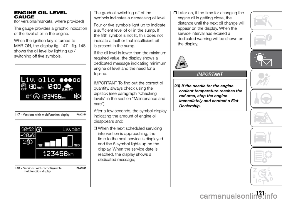
MAR-ON, the display fig. 147 - fig. 148
shows the oil level by lighting up /
switching off five symbols.The gradual switching off of the
symbols indicates a decreasing oil level.
Four or five symbols light up to indicate
a sufficient level of oil in the sump. If
the fifth symbol is not lit, this does not
indicate a fault or that insufficient oil
is present in the sump.
If the oil level is lower than the minimum
required value, the display shows a
dedicated message indicating minimum
engine oil level and the need for a
top-up.
IMPORTANT To find out the correct oil
quantity, always check using the
dipstick (see paragraph “Checking
levels” in the section “Maintenance and
care”).
After a few seconds, the symbol display
indicating the amount of engine oil
disappears and:
❒When the next scheduled servicing
intervention is approaching, the
time to the next service is displayed
and the õ symbol lights up on the
display. When the service date is
reached, the display shows a
dedicated message;❒Later on, if the time for changing the
engine oil is getting close, the
distance until the next oil change will
appear on the display. When the
service interval has expired a
dedicated warning will be shown on
the display.
IMPORTANT
20) If the needle for the engine
coolant temperature reaches the
red area, stop the engine
immediately and contact a Fiat
Dealership.
147 - Versions with multifunction displayF1A0354
Liv.olio
MAX MIN
148 - Versions with reconfigurableF1A0355
121
display
multifunction
Page 134 of 387
NoteWhen an oil change is nearly due
and the ignition key is turned to
MAR-ON, the display will show a
dedicated message. Engine
performance will decrease still driving in
these conditions. When the change is
due, the dedicated message will
reappear on the display together with
the activation of both the
and
warning lights. Contact a
Fiat Dealership.
Activating/deactivating
front passenger side
airbags and side bags
for chest protection
(Passenger airbag)
(for versions/markets, where provided)
This function allows the passenger
side airbag to be activated/deactivated.
Proceed as follows:
❒press the MODE button and, after
the message "Bag pass: Off" (to
deactivate) or "Bag pass: On" (to
activate) is displayed by pressing the
andbuttons, press the
MODE button again;
❒the confirmation request message
will appear on the display;
❒by pressing the
or
buttons, select (Yes) (to confirm
activation/deactivation) or (No) (to
cancel);❒press the MODE button briefly and a
message confirming the selection will
be displayed, then you will return to
the menu screen, or hold the button
down to return to the standard
screen without storing.
Daytime running lights
(DRL)
(for versions/markets, where provided)
With this function is possible to turn the
daytime running lights on and off.
Proceed as follows to activate or
deactivate this function:
❒briefly press the MODE button. The
display shows a submenu;
❒briefly press the MODE button. "On"
or "Off" flash on the display,
according to what has been
previously set;
❒press
orto make your
choice;
❒briefly press the MODE button to
return to the submenu screen or hold
the button down to return to the
main menu screen without storing;
❒press the MODE button again to
return to the standard screen or
to the main menu according to the
menu items where you are in.Automatic main beam
headlights
(for versions/markets, where provided)
This function activates/deactivates
the automatic headlights.
Proceed as follows to activate or
deactivate this function:
❒briefly press the MODE button. The
display shows a submenu;
❒briefly press the MODE button. "On"
or "Off" flash on the display,
according to what has been
previously set;
❒press
orto make your
choice;
❒briefly press the MODE button to
return to the submenu screen or hold
the button down to return to the
main menu screen without storing;
❒press the MODE button again to
return to the standard screen or
to the main menu according to the
menu items where you are in.
130
KNOWING THE INSTRUMENT PANEL
Page 135 of 387
Exit Menu
This is the last function that closes the
cycle of settings listed in the menu
screen.
Pressing the MODE button briefly will
return the display to the standard
screen without storing.
Press button
to return to the first
menu item (Speed Beep).
TRIP COMPUTER
IN BRIEF
The Trip computer is used to display
informationon vehicle operation
when the ignition key is turned to
MAR-ON. This function allows you to
define two separate trips, called
"Trip A" and "Trip B", for monitoring
the "complete mission" (journey)
of the vehicle in a reciprocally
independent manner. Both functions
can be reset (reset means start of
a new journey).
“Trip A” is used to display the figures
relating to:
❒Outside temperature
❒Range
❒Distance travelled A
❒Average consumption A
❒Instant fuel consumption
❒Average speed A
❒Trip time A (driving time).
❒Reset Trip A
"Trip B", available on multifunction
display only, is used to display
the values relating to:❒Distance travelled B
❒Average consumption B
❒Average speed B
❒Trip time B (driving time).21)
Values displayed
Outside temperature
Indicates the temperature outside the
vehicle passenger compartment.
Range (for versions/markets, where
provided)
This indicates the distance that can still
be travelled with the fuel in the tank,
assuming that driving style remains
unvaried. The display will show the
reading '-----' when the following
events take place:
❒range value lower than 50 km (or 30
mi)
❒vehicle is left parked with the engine
running for a long time.
131
Page 136 of 387
IMPORTANT The range can be affected
by several factors: driving style (see
paragraph “Driving style” in the
“Starting and driving” section), type of
route (motorway, towns and cities,
mountain roads, etc…), usage
conditions (load, tyre pressures, etc…).
Trip planning must therefore take the
above into account.
Distance travelled
This value shows the distance covered
from the start of the new journey.
Average consumption (for versions/
markets, where provided)
This value shows the approximate
average fuel consumption from the start
of the new journey.
Instant consumption (for versions/
markets where provided)
This value shows the fuel consumption.
The value is constantly updated. The
display will show “----”ifthecar
is parked with the engine running.Average speed
This value shows the car's average
speed based on the overall time
elapsed since the start of the new
journey.
Trip time
Time elapsed since the start of the new
journey.
IMPORTANT If there is no information,
the Trip computer displays "----" in
place of the value. When normal
operating conditions are restored, the
counting of the various values is
resumed, without either zeroing the
values displayed prior to the problem,
or starting a new mission.
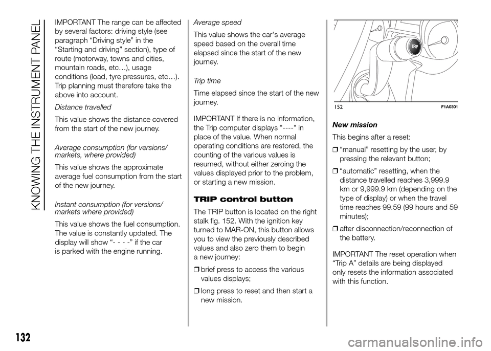
TRIP control button
The TRIP button is located on the right
stalk fig. 152. With the ignition key
turned to MAR-ON, this button allows
you to view the previously described
values and also zero them to begin
a new journey:
❒brief press to access the various
values displays;
❒long press to reset and then start a
new mission.New mission
This begins after a reset:
❒“manual” resetting by the user, by
pressing the relevant button;
❒“automatic” resetting, when the
distance travelled reaches 3,999.9
km or 9,999.9 km (depending on the
type of display) or when the travel
time reaches 99.59 (99 hours and 59
minutes);
❒after disconnection/reconnection of
the battery.
IMPORTANT The reset operation when
“Trip A” details are being displayed
only resets the information associated
with this function.
TRIP
152F1A0301
132
KNOWING THE INSTRUMENT PANEL
Page 137 of 387
IMPORTANT The reset operation when
“Trip B” details are being displayed
resets only the information associated
with this function.
Start of journey procedure
With the ignition key in the MAR-ON
position, reset by pressing the TRIP
button and keeping it pressed for more
than 2 seconds.
Trip Exit
You can automatically exit the TRIP
function once all the values have been
displayed or by holding the MODE
button down for more than 1 second.
IMPORTANT
21) The “Trip B” function may be
disabled (see paragraph
“Activating Trip B”). “Range” and
“Instant consumption"
parameters cannot be reset.
133