Slope FIAT DUCATO 2015 3.G Owners Manual
[x] Cancel search | Manufacturer: FIAT, Model Year: 2015, Model line: DUCATO, Model: FIAT DUCATO 2015 3.GPages: 387, PDF Size: 20.76 MB
Page 87 of 387
HILL HOLDER SYSTEM
This system is an integral part of the
ESC system and facilitates starting on
slopes.
It is automatically activated in the
following conditions:
❒uphill: vehicle stationary on a road
with a gradient higher than 5%,
engine running, brake pressed and
gearbox in neutral or gear (other than
reverse) engaged;
❒downhill: vehicle stationary on a road
with a gradient higher than 5%,
engine running, brake pressed and
reverse gear engaged.
When setting off, the ESC system
control unit maintains the braking
pressure on the wheels until the torque
necessary for starting is reached, or
in any case for a maximum of 2
seconds, allowing your right foot to be
moved easily from the brake pedal to
the accelerator.
When two seconds have elapsed,
without starting, the system is
automatically deactivated, gradually
releasing the braking pressure. During
this release stage, the typical brake
disengagement noise indicating that the
vehicle is going to move imminently
will be heard.IMPORTANT The Hill Holder system is
not a parking brake; therefore, never
leave the vehicle without having
engaged the handbrake, turned the
engine off and engaged first gear,
so that it is parked in safe conditions
(for further information read the
"Parking" paragraph in the "Starting
and driving" chapter).
ASR (AntiSlip
Regulation) SYSTEM
It is an integral part of the ESC system.
It automatically operates in the event
of one or both drive wheels slipping,
loss of grip on wet roads (aquaplaning)
and acceleration on slippery, snowy
or icy roads, etc.
Depending on the slipping conditions,
two different control systems are
activated:
❒if the slipping involves both drive
wheels, the ASR intervenes reducing
the power transmitted by the engine;
❒if the slipping only involves one of the
drive wheels, it intervenes
automatically braking the wheel that
is slipping.
62)
Engagement/ disengagement of the
ASR system
The ASR system switches on
automatically each time the engine is
started.
Whilst driving, the ASR can be switched
off and subsequently switched on
again by pressing the ASR OFF button
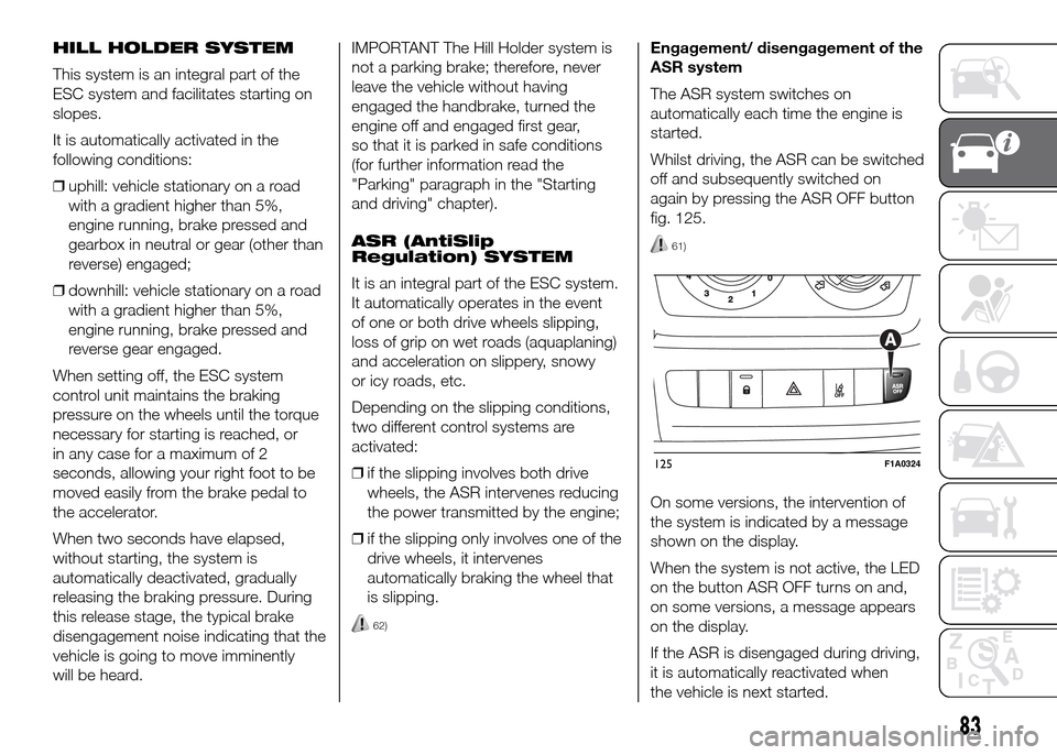
fig. 125.
61)
On some versions, the intervention of
the system is indicated by a message
shown on the display.
When the system is not active, the LED
on the button ASR OFF turns on and,
on some versions, a message appears
on the display.
If the ASR is disengaged during driving,
it is automatically reactivated when
the vehicle is next started.
125F1A0324
83
Page 164 of 387
SEAT BELTS
USING THE SEAT BELTS
The belt should be worn keeping the
torso straight and rested against the
backrest.
To fasten the seat belts, hold the
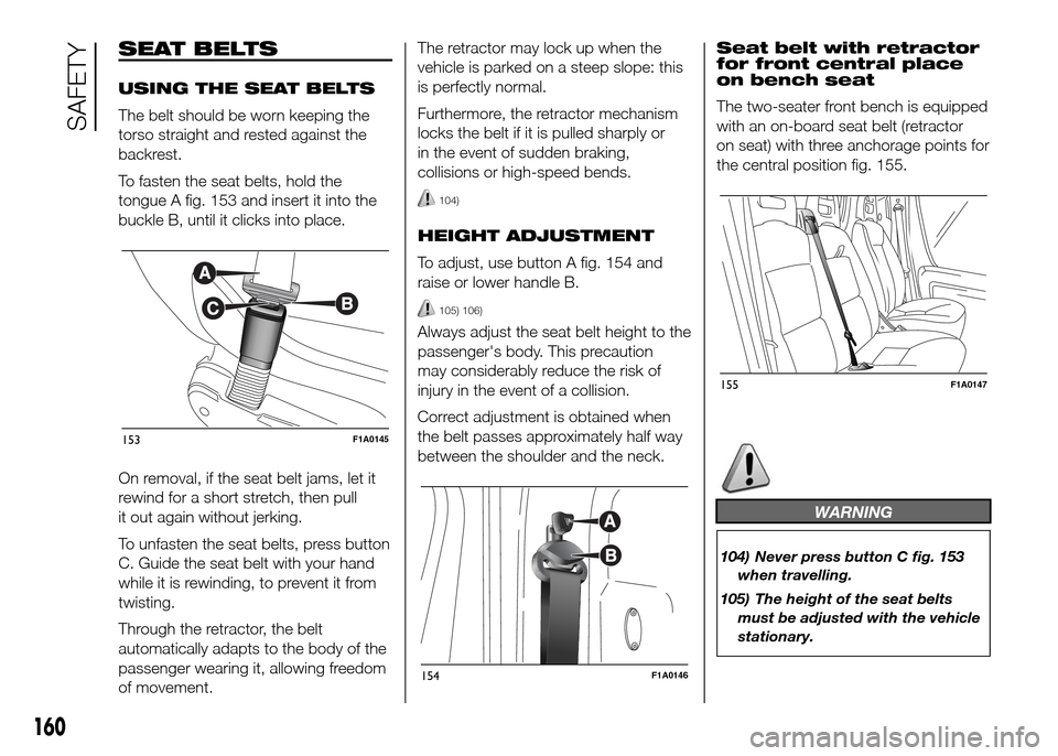
tongue A fig. 153 and insert it into the
buckle B, until it clicks into place.
On removal, if the seat belt jams, let it
rewind for a short stretch, then pull
it out again without jerking.
To unfasten the seat belts, press button
C. Guide the seat belt with your hand
while it is rewinding, to prevent it from
twisting.
Through the retractor, the belt
automatically adapts to the body of the
passenger wearing it, allowing freedom
of movement.The retractor may lock up when the
vehicle is parked on a steep slope: this
is perfectly normal.
Furthermore, the retractor mechanism
locks the belt if it is pulled sharply or
in the event of sudden braking,
collisions or high-speed bends.
104)
HEIGHT ADJUSTMENT
To adjust, use button A fig. 154 and
raise or lower handle B.
105) 106)
Always adjust the seat belt height to the
passenger's body. This precaution
may considerably reduce the risk of
injury in the event of a collision.
Correct adjustment is obtained when
the belt passes approximately half way
between the shoulder and the neck.Seat belt with retractor
for front central place
on bench seat
The two-seater front bench is equipped
with an on-board seat belt (retractor
on seat) with three anchorage points for
the central position fig. 155.
WARNING
104) Never press button C fig. 153
when travelling.
105) The height of the seat belts
must be adjusted with the vehicle
stationary.
153F1A0145
154F1A0146
155F1A0147
160
SAFETY
Page 189 of 387
30) Remember that the brake servo
and power steering are not
operational until the engine has
been started, so you need to apply
much more force than usual to
the brake pedal and steering
wheel.
31) Never start the engine by
pushing, towing or driving
downhill. This could cause fuel to
flow into the catalytic converter
and damage it beyond repair.
32) A quick burst on the accelerator
before turning off the engine
serves absolutely no practical
purpose; it wastes fuel and is
especially damaging to
turbocharged engines.
33) In some cases, when the engine
switches off, the fan could
activate for max. 120 seconds.
WARNING
134) It is dangerous to run the
engine in enclosed areas. The
engine takes in oxygen and
releases carbon dioxide, carbon
monoxide and other toxic gases.
PARKING
Proceed as follows:
❒stop the engine and engage the
handbrake;
❒engage a gear (on a slope, engage
first gear if the car is facing uphill or
reverse if it is facing downhill) and
leave the wheels steered.
If the vehicle is parked on a steep
slope, it is advisable to block the
wheels with a wedge or stone.
Do not leave the key in the ignition as
this drains the battery. Always remove
the key when you leave the car.
135)
HANDBRAKE
The handbrake lever is located to the
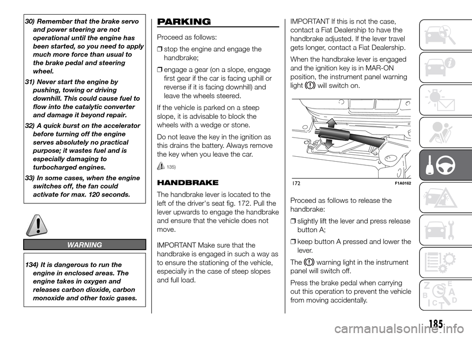
left of the driver's seat fig. 172. Pull the
lever upwards to engage the handbrake
and ensure that the vehicle does not
move.
IMPORTANT Make sure that the
handbrake is engaged in such a way as
to ensure the stationing of the vehicle,
especially in the case of steep slopes
and full load.IMPORTANT If this is not the case,
contact a Fiat Dealership to have the
handbrake adjusted. If the lever travel
gets longer, contact a Fiat Dealership.
When the handbrake lever is engaged
and the ignition key is in MAR-ON
position, the instrument panel warning
light
will switch on.
Proceed as follows to release the
handbrake:
❒slightly lift the lever and press release
button A;
❒keep button A pressed and lower the
lever.
The
warning light in the instrument
panel will switch off.
Press the brake pedal when carrying
out this operation to prevent the vehicle
from moving accidentally.
172F1A0162
185
Page 207 of 387
WARNING
145) This procedure must be
performed by qualified personnel
as incorrect actions may cause
high-intensity electrical discharge.
Furthermore, battery fluid is
poisonous and corrosive: avoid
contact with skin and eyes. Keep
naked flames and lighted
cigarettes away from the battery
and do not cause sparks.
REPLACING A
WHEEL
GENERAL
INSTRUCTIONS
Wheel replacement and correct use of
the jack and spare wheel (for
versions/markets, where provided) call
for some precautions, which are listed
below.
146) 147) 148) 149) 150)
Please note that:
❒the jack weight is 4.5 kg;
❒the jack requires no adjustment;
❒the jack cannot be repaired: in the
event of a fault it must be replaced by
another original one;
❒no tool other than its cranking device
may be fitted on the jack.
151)
To change a wheel,
proceed as follows:
❒stop the vehicle in a position that is
not dangerous for oncoming traffic
where you can change the wheel
safely. The ground should be flat
if possible, and sufficiently firm;
❒stop the engine and pull the
handbrake;
❒engage first gear or reverse;
❒put on the reflective safety jacket
(compulsory by law in certain
countries) before getting out of the
vehicle;
❒indicate that the vehicle has broken
down using the devices required by
the law in the current country (e.g.
warning triangle, hazard lights, etc.);
❒In the event of a wheel change on a
slope or on unsurfaced roads, put
any object as stop under the wheels;
❒take the tool bag under the
passenger seat (see “Compartment
under front passenger seat” in the
“Know your vehicle” section);
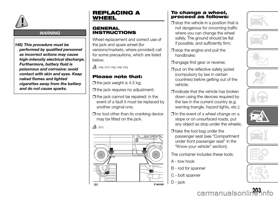
The container includes these tools:
A - tow hook
B - rod for spanner
C - bolt spanner
D - jack
181F1A0168
203
Page 211 of 387
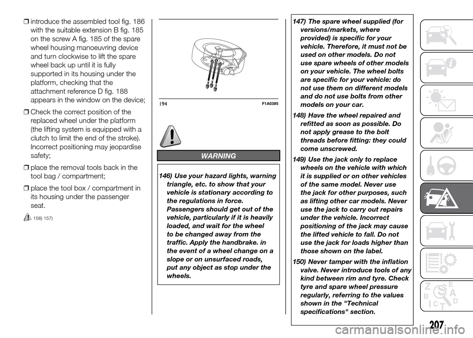
❒introduce the assembled tool fig. 186
with the suitable extension B fig. 185
on the screw A fig. 185 of the spare
wheel housing manoeuvring device
and turn clockwise to lift the spare
wheel back up until it is fully
supported in its housing under the
platform, checking that the
attachment reference D fig. 188
appears in the window on the device;
❒Check the correct position of the
replaced wheel under the platform
(the lifting system is equipped with a
clutch to limit the end of the stroke).
Incorrect positioning may jeopardise
safety;
❒place the removal tools back in the
tool bag / compartment;
❒place the tool box / compartment in
its housing under the passenger
seat.
156) 157)
WARNING
146) Use your hazard lights, warning
triangle, etc. to show that your
vehicle is stationary according to
the regulations in force.
Passengers should get out of the
vehicle, particularly if it is heavily
loaded, and wait for the wheel
to be changed away from the
traffic. Apply the handbrake. in
the event of a wheel change on a
slope or on unsurfaced roads,
put any object as stop under the
wheels.147) The spare wheel supplied (for
versions/markets, where
provided) is specific for your
vehicle. Therefore, it must not be
used on other models. Do not
use spare wheels of other models
on your vehicle. The wheel bolts
are specific for your vehicle: do
not use them on different models
and do not use bolts from other
models on your car.
148) Have the wheel repaired and
refitted as soon as possible. Do
not apply grease to the bolt
threads before fitting: they could
come unscrewed.
149) Use the jack only to replace
wheels on the vehicle with which
it is supplied or on other vehicles
of the same model. Never use
the jack for other purposes, such
as lifting other car models. Never
use the jack to carry out repairs
under the vehicle. Incorrect
positioning of the jack may cause
the lifted vehicle to fall. Do not
use the jack for loads higher than
those shown on the label.
150) Never tamper with the inflation
valve. Never introduce tools of any
kind between rim and tyre. Check
tyre and spare wheel pressure
regularly, referring to the values
shown in the "Technical
specifications" section.
194F1A0385
207