brake light FIAT DUCATO 2015 Owner handbook (in English)
[x] Cancel search | Manufacturer: FIAT, Model Year: 2015, Model line: DUCATO, Model: FIAT DUCATO 2015Pages: 367, PDF Size: 19.73 MB
Page 6 of 367
READ THIS CAREFULLY
REFUELLING
Only refuel with automotive diesel conforming to the European specification EN590. The use of other products or mixtures may damage the
engine beyond repair and consequently invalidate the warranty, due to the damage caused.
STARTING THE ENGINE
Make sure that the handbrake is engaged; set the gear lever to neutral; fully depress the clutch pedal without pressing the accelerator, then
turn the ignition key to MAR-ON and wait for the warning lightsandto switch off; turn the ignition key to AVV and release it as
soon as the engine has started.
PARKING ON FLAMMABLE MATERIAL
The catalytic converter develops high temperatures during operation. Do not park on grass, dry leaves, pine needles or other flammable
material: fire hazard.
RESPECTING THE ENVIRONMENT
The vehicle is fitted with a system that allows continuous diagnosis of the emission-related components in order to help protect the
environment.
ELECTRICAL ACCESSORIES
If, after buying the vehicle, you decide to add electrical accessories (with the risk of gradually draining the battery), visit a Fiat Dealership. They
can calculate the overall electrical requirement and check that the vehicle's electrical system can support the required load.
SCHEDULED SERVICING
Correct maintenance enables the vehicle to perfectly maintain performance and safety characteristics, its environmental friendliness and low
running costs over time.
THE OWNER HANDBOOK CONTAINS
... important information, advice and warnings for correct use, driving safety and maintenance of your vehicle over time. Special attention
must be paid to the symbols(safety of persons)(environmental protection)(vehicle integrity).
Page 10 of 367
.
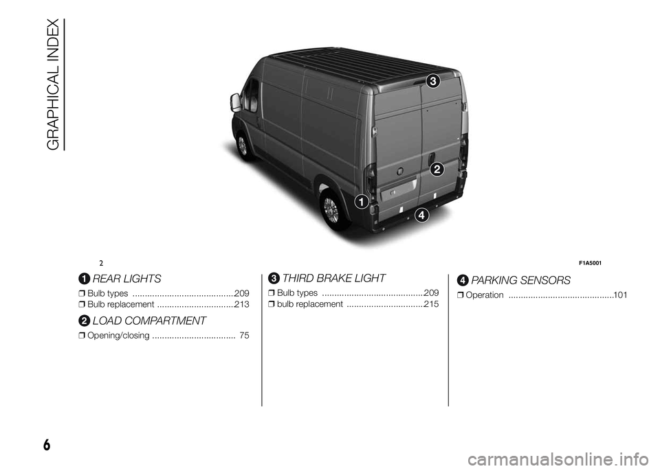
REAR LIGHTS
❒Bulb types ..........................................209
❒Bulb replacement ................................213
LOAD COMPARTMENT
❒Opening/closing .................................. 75
THIRD BRAKE LIGHT
❒Bulb types ..........................................209
❒bulb replacement ................................215
PARKING SENSORS
❒Operation ...........................................101
2F1A5001
6
GRAPHICAL INDEX
Page 19 of 367
IGNITION SWITCH
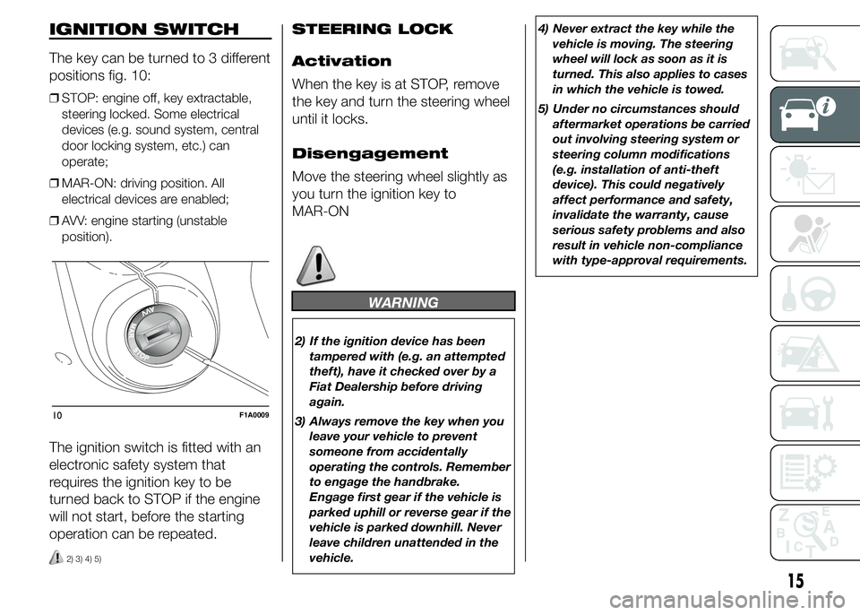
The key can be turned to 3 different
positions fig. 10:
❒STOP: engine off, key extractable,
steering locked. Some electrical
devices (e.g. sound system, central
door locking system, etc.) can
operate;
❒MAR-ON: driving position. All
electrical devices are enabled;
❒AVV: engine starting (unstable
position).
The ignition switch is fitted with an
electronic safety system that
requires the ignition key to be
turned back to STOP if the engine
will not start, before the starting
operation can be repeated.
2) 3) 4) 5)
STEERING LOCK
Activation
When the key is at STOP, remove
the key and turn the steering wheel
until it locks.
Disengagement
Move the steering wheel slightly as
you turn the ignition key to
MAR-ON
WARNING
2) If the ignition device has been
tampered with (e.g. an attempted
theft), have it checked over by a
Fiat Dealership before driving
again.
3) Always remove the key when you
leave your vehicle to prevent
someone from accidentally
operating the controls. Remember
to engage the handbrake.
Engage first gear if the vehicle is
parked uphill or reverse gear if the
vehicle is parked downhill. Never
leave children unattended in the
vehicle.4) Never extract the key while the
vehicle is moving. The steering
wheel will lock as soon as it is
turned. This also applies to cases
in which the vehicle is towed.
5) Under no circumstances should
aftermarket operations be carried
out involving steering system or
steering column modifications
(e.g. installation of anti-theft
device). This could negatively
affect performance and safety,
invalidate the warranty, cause
serious safety problems and also
result in vehicle non-compliance
with type-approval requirements.
10F1A0009
15
Page 60 of 367
Storing vehicle speed
Proceed as follows:
❒turn ring nut A fig. 66 - fig. 67 to ON
or
(according to the version) and
press the accelerator pedal so that
the vehicle reaches the desired
speed;
❒move the stalk upwards (+) for at
least one second, then release it. The
vehicle speed is now stored and
you can therefore release the
accelerator pedal.
If necessary (e.g. when overtaking)
acceleration is possible by simply
pressing the accelerator pedal:
releasing the accelerator pedal the
car will return to the speed stored
previously.
Restoring the stored
speed
If the device has been deactivated,
for example by depressing the
brake or clutch pedal, the stored
speed can be restored as follows:
❒accelerate progressively until a speed
close to that stored is reached;
❒engage the gear selected at the time
that the speed was stored;
❒press button B fig. 66 - fig. 67.
Increasing the stored
speed
This can be done in two ways:
❒by pressing the accelerator
and storing the new speed reached
or
❒by moving the stalk upwards (+).
Each activation of the lever
corresponds to an increase in
speed of about 1 km/h, whilst
keeping the lever upwards varies
the speed continuously.
Reducing the stored
speed
This can be done in two ways:
❒by switching off the device and then
storing the new speed;
or
❒by moving the stalk downwards (-)
until the new speed, which will be
stored automatically, is reached.
Each movement of the lever will
correspond to a slight reduction in
speed of about 1 km/h, while
keeping the lever held downwards
will decrease the speed
continuously.Deactivating the
device
The device can be switched off by
the driver in the following ways:
❒turning ring nut A to OFF orO
(according to the version);
❒by stopping the engine;
Deactivating the
function
The device can be switched off by
the driver in the following ways:
❒turning ring nut A to OFF orO
(according to the version);
❒pressing the button B, both with
symbolIIand symbol CANC/RES,
the system pauses;
❒by stopping the engine;
❒by pressing the brake pedal or
operating the handbrake;
❒by pressing the clutch pedal;
❒requesting a gear shift with an
automatic transmission in sequential
mode;
❒with the vehicle speed below the set
limit
56
KNOW YOUR VEHICLE
Page 86 of 367
ABS
This is an integral part of the
braking system, which prevents
one or more wheels from locking or
slipping regardless of the road
surface conditions and braking
intensity, ensuring control of the
vehicle even during emergency
braking.
The system intervenes when
braking and the wheels are about
to lock, typically in emergency
braking or low-grip conditions,
when locking may be more
frequent.
The ABS ensures the direction of
the vehicle while braking and
optimises the braking distances at
the same time.
The system also improves control
and stability of the car when
braking on a surface where the grip
of the left and right wheels varies,
or when braking on corners.
The system is completed by EBD
(Electronic Braking Force
Distribution), which distributes the
braking action between the front
and rear wheels.IMPORTANT To obtain the
maximum efficiency of the braking
system, a bedding-in period of
about 500 km is needed: during
this period it is better to avoid
sharp, repeated and prolonged
braking.
50)
SYSTEM
INTERVENTION
The driver can feel that the ABS
has come into action because the
brake pedal pulsates slightly and
the system gets noisier: it means
that the car speed should be
altered to suit the type of road
surface.
51) 52) 52) 53) 54) 55) 56) 57)
MSR SYSTEM
(Motor Schleppmoment
Regelung)
This system is an integral part of
the ABS and intervenes, if there is
sudden downshifting, restoring
torque to the engine, thereby
preventing excessive drive at the
drive wheels which, especially
in poor grip conditions, could lead
to a loss in stability of the vehicle.
WARNING
50) The ABS exploits the grip
available to the full, but it cannot
improve it. Therefore, you should
take great care when driving on
slippery surfaces, without taking
unnecessary risks.
51) When the ABS intervenes and
you notice the brake pedal
pulsating, keep the pedal pushed
down and don’t be alarmed. This
will help you to stop in the
shortest distance possible,
depending on the road conditions.
52) If the ABS intervenes, it means
you have almost reached the grip
limit between the tyres and the
road surface: slow down to make
sure that you drive in accordance
with the available grip
82
KNOW YOUR VEHICLE
Page 87 of 367
53) The ABS can’t overrule the
natural laws of physics, and can’t
increase the grip available
according to the condition of the
road.
54) The ABS cannot prevent
accidents, including those due to
excessive speed on corners,
driving on low-grip surfaces or
aquaplaning.
55) The capability of the ABS must
never be tested irresponsibly and
dangerously, in such a way as
to compromise personal safety
and the safety of others.
56) For the correct operation of the
ABS, it is essential that the tyres
are of the same make and type on
all wheels, in perfect condition
and, above all, of the specified
type and dimensions.
57) If the space-saver wheel (for
versions/markets, where
provided) is used, the ABS keeps
operating. Always remember
that the space-saver wheel, being
smaller than the original wheel,
provides less grip.ESC (Electronic
Stability Control)
SYSTEM
(for versions/markets, where
provided)
The ESC system improves the
directional control and stability of
the vehicle in various driving
conditions.
The ESC system corrects the
vehicle’s understeer and oversteer,
distributing the brake force on
the appropriate wheels. The torque
supplied by the engine can also
be reduced in order to maintain
control of the vehicle.
The ESC system uses the sensors
in the vehicle to determine the
trajectory required by the driver
through steering and compares it
with the real trajectory of the
vehicle. When the real trajectory
deviates from the desired trajectory,
the ESC system intervenes to
counter the car’s understeer or
oversteer.
❒Oversteer: occurs when the vehicle is
turning more than it should according
to the angle of the steering wheel.❒Understeer: occurs when the vehicle
is turning less than it should
according to the angle of the steering
wheel
The ESC system also includes the
following subsystems:
❒Hill Holder
❒ASR
❒HBA
❒ERM
❒HDC
58) 59) 60)
SYSTEM
INTERVENTION
This is signalled by the flashing of
warning light
in the instrument
panel, to inform the driver that
the vehicle is in critical stability and
grip conditions.
SYSTEM ACTIVATION
The ESC system switches on
automatically when the engine is
started and cannot be switched off.
83
Page 90 of 367
HILL DESCENT
CONTROL (HDC)
SYSTEM
It is an integral part of the ESC and
is aimed at keeping the vehicle at
a constant speed during a descent,
operating autonomously on the
brakes in various ways at the same
time. In this way the vehicle stability
and completely safe driving are
guaranteed, above all in poor grip
conditions and/or steep descents.
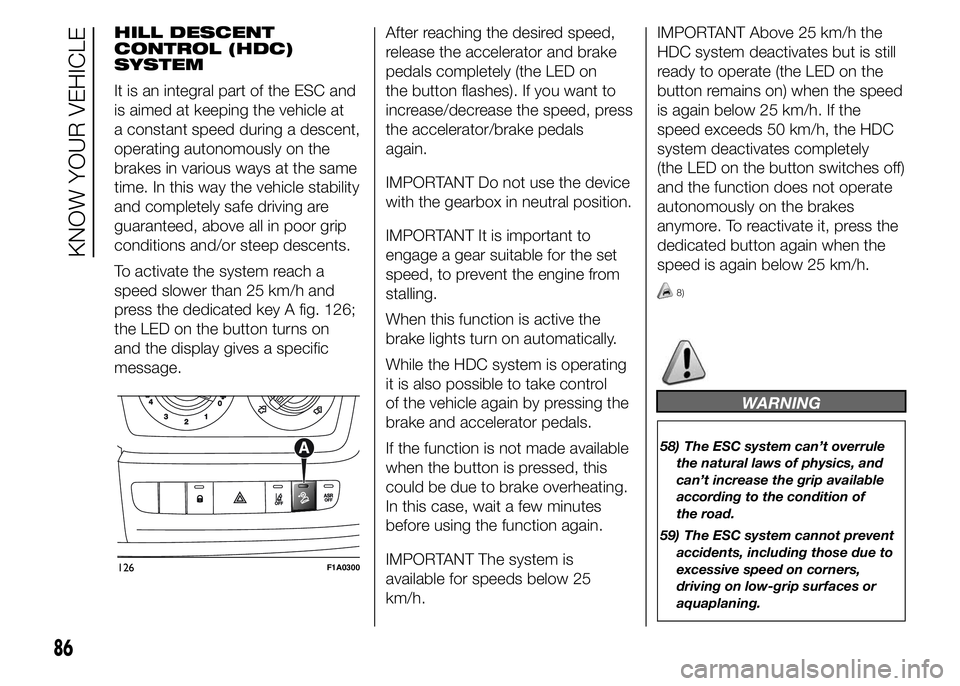
To activate the system reach a
speed slower than 25 km/h and
press the dedicated key A fig. 126;
the LED on the button turns on
and the display gives a specific
message.After reaching the desired speed,
release the accelerator and brake
pedals completely (the LED on
the button flashes). If you want to
increase/decrease the speed, press
the accelerator/brake pedals
again.
IMPORTANT Do not use the device
with the gearbox in neutral position.
IMPORTANT It is important to
engage a gear suitable for the set
speed, to prevent the engine from
stalling.
When this function is active the
brake lights turn on automatically.
While the HDC system is operating
it is also possible to take control
of the vehicle again by pressing the
brake and accelerator pedals.
If the function is not made available
when the button is pressed, this
could be due to brake overheating.
In this case, wait a few minutes
before using the function again.
IMPORTANT The system is
available for speeds below 25
km/h.IMPORTANT Above 25 km/h the
HDC system deactivates but is still
ready to operate (the LED on the
button remains on) when the speed
is again below 25 km/h. If the
speed exceeds 50 km/h, the HDC
system deactivates completely
(the LED on the button switches off)
and the function does not operate
autonomously on the brakes
anymore. To reactivate it, press the
dedicated button again when the
speed is again below 25 km/h.
8)
WARNING
58) The ESC system can’t overrule
the natural laws of physics, and
can’t increase the grip available
according to the condition of
the road.
59) The ESC system cannot prevent
accidents, including those due to
excessive speed on corners,
driving on low-grip surfaces or
aquaplaning.
126F1A0300
86
KNOW YOUR VEHICLE
Page 101 of 367
REAR CAMERA
(PARKVIEW® REAR
BACK UP CAMERA)
(for versions/markets, where
provided)
9)
81)
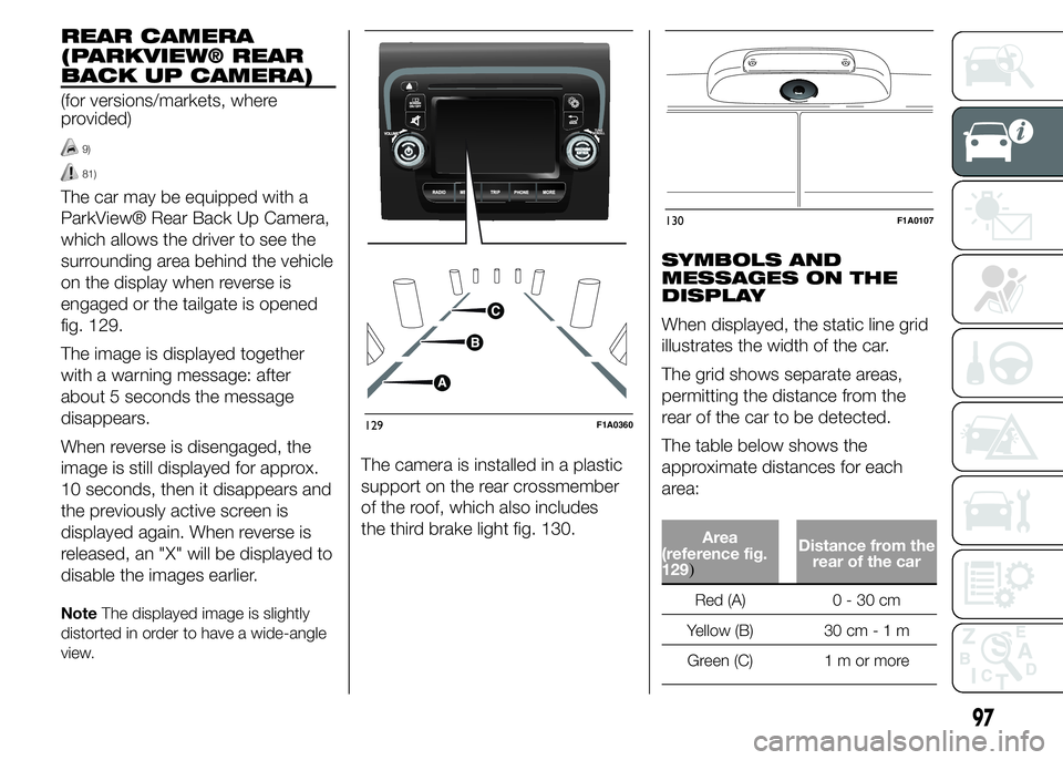
The car may be equipped with a
ParkView® Rear Back Up Camera,
which allows the driver to see the
surrounding area behind the vehicle
on the display when reverse is
engaged or the tailgate is opened
fig. 129.
The image is displayed together
with a warning message: after
about 5 seconds the message
disappears.
When reverse is disengaged, the
image is still displayed for approx.
10 seconds, then it disappears and
the previously active screen is
displayed again. When reverse is
released, an "X" will be displayed to
disable the images earlier.
NoteThe displayed image is slightly
distorted in order to have a wide-angle
view.
The camera is installed in a plastic
support on the rear crossmember
of the roof, which also includes
the third brake light fig. 130.SYMBOLS AND
MESSAGES ON THE
DISPLAY
When displayed, the static line grid
illustrates the width of the car.
The grid shows separate areas,
permitting the distance from the
rear of the car to be detected.
The table below shows the
approximate distances for each
area:
Area
(reference fig.
129
)
Distance from the
rear of the car
Red (A) 0 - 30 cm
Yellow (B) 30 cm-1m
Green (C) 1 m or more
129F1A0360
130F1A0107
97
Page 106 of 367
FAULT INDICATIONS
Any parking sensor faults will be
indicated when reverse is engaged
by the warning light
in the
instrument panel or by the icon
on the display and by the
message in the multifunction
display (for versions/markets, where
provided)
OPERATION WITH
TRAILER
Parking sensor operation is
automatically deactivated when the
electric cable plug of the trailer is
inserted into the vehicle tow hook
socket.
The sensors are automatically
reactivated when the trailer's cable
plug is removed.
17)
86)
IMPORTANT If you wish to leave
the tow hook fitted without towing a
trailer, it is advisable to contact a
Fiat Dealership for the relevant
system update operations because
the tow hook could be detected
as an obstacle by the central
sensors.When using special washing
equipment such as high pressure
jets or steam cleaning, clean the
sensors very quickly keeping the jet
more than 10 cm away.
IMPORTANT
INFORMATION
❒Do not apply stickers to the sensors.
❒When parking, take the utmost
care over obstacles that may be
above or under the sensor.
❒Objects close to the vehicle, in
certain circumstances are not
detected and could therefore cause
damage to the vehicle or be
damaged.
The following conditions may
influence the performance of the
parking assistance system:
❒Reduced sensor sensitivity and a
reduction in the parking assistance
system performance could be due to
the presence on the surface of the
sensor of: ice, snow, mud, thick
paint.❒The sensor may detect a non-
existent obstacle (echo noise) due to
mechanical noises, for example
when washing the vehicle, in case of
rain, strong wind, hail.
❒The signals sent by the sensors can
also be altered by the presence of
ultrasonic systems (e.g. pneumatic
brake systems or pneumatic drills)
near the vehicle.
❒The performance of the parking
assistance system may also be
affected by the position of the
sensors. For example by a change in
the ride setting (caused by the wear
of the shock absorbers, suspension),
changing the tyres, overloading the
vehicle and carrying out specific
tuning operations that require the
vehicle to be lowered.
❒Detection of obstacles in the upper
part of the vehicle (particularly in the
case of vans or chassis cabs) may
not be guaranteed because the
system detects obstacles that could
strike the lower part of the vehicle.
102
KNOW YOUR VEHICLE
Page 117 of 367
KNOWING THE INSTRUMENT PANEL
This section of the booklet gives
you all the information you need to
understand, interpret and use
the instrument panel correctly.CONTROL PANEL AND
INSTRUMENTS ...............................114
DISPLAY ........................................120
TRIP COMPUTER ...........................129
WARNING LIGHTS AND
MESSAGES ....................................132
- LOW BRAKE FLUID/HANDBRAKE
ENGAGED .......................................... 132
- EBD FAILURE .................................. 133
- AIRBAG FAILURE ............................. 133
- SEAT BELTS NOT FASTENED .......... 134
- ENGINE COOLANT TEMPERATURE
TOO HIGH .......................................... 135
- LOW BATTERY CHARGE ................. 135
- LOW ENGINE OIL PRESSURE ......... 136
-ENGINE OIL DETERIORATED ........... 136
-INCOMPLETE DOOR/LOAD
COMPARTMENT CLOSURE ............... 137
- POWER STEERING FAILURE ........... 137
-SELF-LEVELLING SUSPENSION
FAILURE ............................................. 137
- INJECTION/EOBD SYSTEM
FAILURE ............................................. 139
- ABS FAILURE ................................... 140
-FUEL RESERVE ................................ 140
- GLOW PLUG HEATING/GLOW
PLUG HEATING FAILURE ................... 141
- WATER IN DIESEL FILTER ................ 141
-VEHICLE PROTECTION SYSTEM
FAILURE - FIAT CODE ........................ 142
- REAR FOG LIGHTS .......................... 142
-GENERIC FAILURE INDICATION ....... 142
-DPF (PARTICULATE FILTER)
CLEANING UNDERWAY ..................... 144
-WORN BRAKE PADS ........................ 145
-DRIVING ADVISOR ........................... 146
- TPMS ............................................... 147
- DIPPED HEADLIGHTS ..................... 148- FOLLOW ME HOME ........................ 148
- LEFT-HAND DIRECTION INDICATOR
............................................................ 148
- RIGHT-HAND DIRECTION
INDICATOR ........................................ 149
-FOG LIGHTS ..................................... 149
- CRUISE CONTROL .......................... 149
-SPEED LIMITER ................................ 149
- AUTOMATIC MAIN BEAM
HEADLIGHTS ..................................... 150
- MAIN BEAM HEADLIGHTS .............. 150
-EXTERIOR LIGHTS FAULT ................ 151
-BRAKE LIGHT FAILURE .................... 151
-MAIN BEAM AUTOMATISM FAULT ... 152
-POSSIBLE ICE ON ROAD ................. 152
-SPEED LIMIT EXCEEDED ................. 152
-SCHEDULED SERVICING ................. 152
-DRIVING ADVISOR SYSTEM
FAILURE ............................................. 153
-TRAFFIC SIGN RECOGNITION
FAILURE ............................................. 153
-LIMITED RANGE ............................... 153
-START&STOP SYSTEM
ACTIVATION/DEACTIVATION .............. 154
-START&STOP FAILURE .................... 154
113