fuel FIAT DUCATO 2015 Owner handbook (in English)
[x] Cancel search | Manufacturer: FIAT, Model Year: 2015, Model line: DUCATO, Model: FIAT DUCATO 2015Pages: 367, PDF Size: 19.73 MB
Page 6 of 367
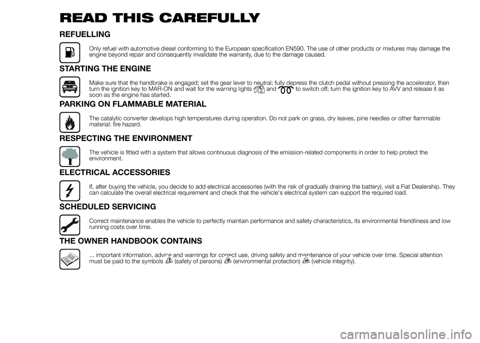
READ THIS CAREFULLY
REFUELLING
Only refuel with automotive diesel conforming to the European specification EN590. The use of other products or mixtures may damage the
engine beyond repair and consequently invalidate the warranty, due to the damage caused.
STARTING THE ENGINE
Make sure that the handbrake is engaged; set the gear lever to neutral; fully depress the clutch pedal without pressing the accelerator, then
turn the ignition key to MAR-ON and wait for the warning lightsandto switch off; turn the ignition key to AVV and release it as
soon as the engine has started.
PARKING ON FLAMMABLE MATERIAL
The catalytic converter develops high temperatures during operation. Do not park on grass, dry leaves, pine needles or other flammable
material: fire hazard.
RESPECTING THE ENVIRONMENT
The vehicle is fitted with a system that allows continuous diagnosis of the emission-related components in order to help protect the
environment.
ELECTRICAL ACCESSORIES
If, after buying the vehicle, you decide to add electrical accessories (with the risk of gradually draining the battery), visit a Fiat Dealership. They
can calculate the overall electrical requirement and check that the vehicle's electrical system can support the required load.
SCHEDULED SERVICING
Correct maintenance enables the vehicle to perfectly maintain performance and safety characteristics, its environmental friendliness and low
running costs over time.
THE OWNER HANDBOOK CONTAINS
... important information, advice and warnings for correct use, driving safety and maintenance of your vehicle over time. Special attention
must be paid to the symbols(safety of persons)(environmental protection)(vehicle integrity).
Page 13 of 367
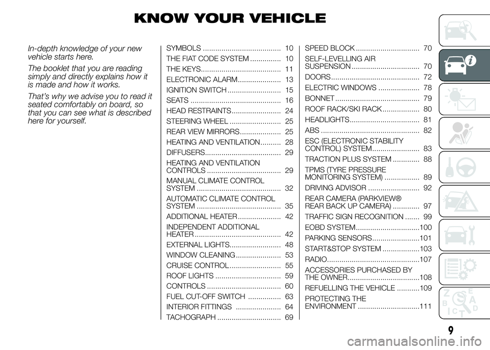
KNOW YOUR VEHICLE
In-depth knowledge of your new
vehicle starts here.
The booklet that you are reading
simply and directly explains how it
is made and how it works.
That’s why we advise you to read it
seated comfortably on board, so
that you can see what is described
here for yourself.SYMBOLS ...................................... 10
THE FIAT CODE SYSTEM ............... 10
THE KEYS....................................... 11
ELECTRONIC ALARM..................... 13
IGNITION SWITCH .......................... 15
SEATS ............................................ 16
HEAD RESTRAINTS ........................ 24
STEERING WHEEL ......................... 25
REAR VIEW MIRRORS .................... 25
HEATING AND VENTILATION.......... 28
DIFFUSERS..................................... 29
HEATING AND VENTILATION
CONTROLS .................................... 29
MANUAL CLIMATE CONTROL
SYSTEM ......................................... 32
AUTOMATIC CLIMATE CONTROL
SYSTEM ......................................... 35
ADDITIONAL HEATER ..................... 42
INDEPENDENT ADDITIONAL
HEATER .......................................... 42
EXTERNAL LIGHTS......................... 48
WINDOW CLEANING ...................... 53
CRUISE CONTROL ......................... 55
ROOF LIGHTS ................................ 59
CONTROLS .................................... 60
FUEL CUT-OFF SWITCH ................ 63
INTERIOR FITTINGS ...................... 64
TACHOGRAPH ............................... 69SPEED BLOCK ............................... 70
SELF-LEVELLING AIR
SUSPENSION ................................. 70
DOORS ........................................... 72
ELECTRIC WINDOWS .................... 78
BONNET ......................................... 79
ROOF RACK/SKI RACK .................. 80
HEADLIGHTS.................................. 81
ABS ................................................ 82
ESC (ELECTRONIC STABILITY
CONTROL) SYSTEM ....................... 83
TRACTION PLUS SYSTEM ............. 88
TPMS (TYRE PRESSURE
MONITORING SYSTEM) ................. 89
DRIVING ADVISOR ......................... 92
REAR CAMERA (PARKVIEW®
REAR BACK UP CAMERA) ............. 97
TRAFFIC SIGN RECOGNITION ....... 99
EOBD SYSTEM...............................100
PARKING SENSORS.......................101
START&STOP SYSTEM ..................103
RADIO.............................................107
ACCESSORIES PURCHASED BY
THE OWNER...................................108
REFUELLING THE VEHICLE ...........109
PROTECTING THE
ENVIRONMENT ..............................111
9
Page 15 of 367
In this case, turn the key toSTOP
and then back toMAR-ON;if
the lock continues, try with the
other keys provided with the
vehicle. Contact a Fiat Dealership if
you still cannot start the engine.
IMPORTANT Each key has its own
code which must be stored by
the system's control unit. Contact
the Fiat Dealership to have new
keys (up to eight) stored with the
code.
Activation of
warning light while
driving
❒If the warning lightswitches
on, this means that the system
is running a self-diagnosis (for
example for a voltage drop).
❒If the warning lightstays on,
contact a Fiat Dealership.
IMPORTANT
1) The electronic components inside
the key may be damaged if the
key is subjected to sharp knocks.
In order to ensure complete
efficiency of the electronic
devices inside the key, it should
never be exposed to direct
sunlight.
THE KEYS
KEY WITHOUT REMOTE
CONTROL
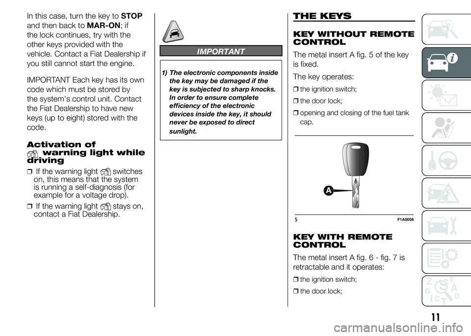
The metal insert A fig. 5 of the key
is fixed.
The key operates:
❒the ignition switch;
❒the door lock;
❒opening and closing of the fuel tank
cap.
KEY WITH REMOTE
CONTROL
The metal insert A fig.6-fig.7is
retractable and it operates:
❒the ignition switch;
❒the door lock;
5F1A0008
11
Page 16 of 367
❒opening and closing of the fuel tank
cap.
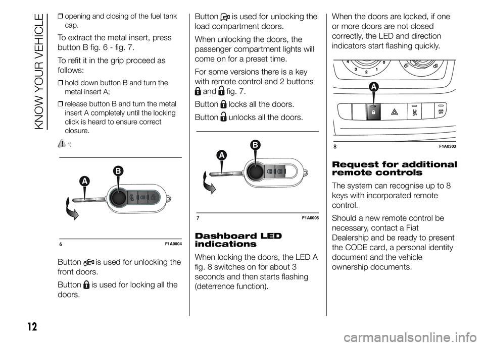
To extract the metal insert, press
button B fig. 6 - fig. 7.
To refit it in the grip proceed as
follows:
❒hold down button B and turn the
metal insert A;
❒release button B and turn the metal
insert A completely until the locking
click is heard to ensure correct
closure.
1)
Buttonis used for unlocking the
front doors.
Button
is used for locking all the
doors.Button
is used for unlocking the
load compartment doors.
When unlocking the doors, the
passenger compartment lights will
come on for a preset time.
For some versions there is a key
with remote control and 2 buttons
andfig. 7.
Button
locks all the doors.
Button
unlocks all the doors.
Dashboard LED
indications
When locking the doors, the LED A
fig. 8 switches on for about 3
seconds and then starts flashing
(deterrence function).When the doors are locked, if one
or more doors are not closed
correctly, the LED and direction
indicators start flashing quickly.
Request for additional
remote controls
The system can recognise up to 8
keys with incorporated remote
control.
Should a new remote control be
necessary, contact a Fiat
Dealership and be ready to present
the CODE card, a personal identity
document and the vehicle
ownership documents.
6F1A0004
7F1A0005
8F1A0303
12
KNOW YOUR VEHICLE
Page 46 of 367
ADDITIONAL
HEATER
(for versions/markets, where
provided)
On some versions, an additional
heater is also present beneath the
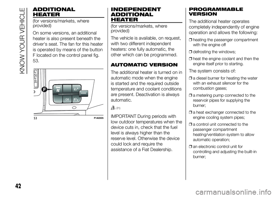
driver's seat. The fan for this heater
is operated by means of the button
F located on the control panel fig.
53.
INDEPENDENT
ADDITIONAL
HEATER
(for versions/markets, where
provided)
The vehicle is available, on request,
with two different independent
heaters: one fully automatic, the
other which can be programmed.
AUTOMATIC VERSION
The additional heater is turned on in
automatic mode when the engine
is started and the required outside
temperature and coolant conditions
are present. Deactivation is always
automatic.
21)
IMPORTANT During periods with
low outdoor temperatures when the
device cuts in, check that the fuel
level is always higher than the
reserve level. Otherwise the device
could lock and require the
assistance of a Fiat Dealership.PROGRAMMABLE
VERSION
The additional heater operates
completely independently of engine
operation and allows the following:
❒heating the passenger compartment
with the engine off
❒defrosting the windows;
❒heat the engine coolant and then the
engine itself prior to starting.
The system consists of:
❒a diesel burner for heating the water
with an exhaust silencer for the
combustion gases;
❒a metering pump connected to the
reservoir pipes for supplying the
burner;
❒a heat exchanger connected to the
engine cooling system pipes;
❒a control unit connected to the
passenger compartment
heating/ventilation system to allow
automatic operation;
❒an electronic control unit for
controlling and adjusting the built-in
burner;
MODEF
53F1A0305
42
KNOW YOUR VEHICLE
Page 50 of 367
Hold button 4 pressed again. At the
same time press button 3 or 8.
The preset activation duration
is displayed and warning light 9 or
2 flashes.
Set the activation duration with
button 3 or 8.
The set activation duration is stored
as soon as the text in the display
disappears, or pressing button 4.
Switching the heating
system off
Deactivation of the system,
depending on the type of activation
(automatic or manual), may be:
❒automaticwhen the programmed
duration is over; when the set time
is over, the display switches off.
❒manualpressing the “immediate
heating” button on the timer again
(flame button 6).
In both cases, the heating warning
light, the display lighting and the
passenger compartment heater fan
go off and burning stops.The fluid circulation pump
continues to work for around two
minutes to dissipate as much
heat as possible; the heater can be
turned back on during this stage.
22)
IMPORTANT The parking heater
goes off when battery voltage is low
to allow the vehicle to be started.
IMPORTANT Before turning on the
device, ensure that the fuel level
is above the reserve. Otherwise the
device could lock and require the
assistance of a Fiat Dealership.
❒Always turn off the heater when
refuelling and near service stations to
avoid the risk of explosion or fire
hazards.
❒Do not park the vehicle on
inflammable material such as paper,
grass or dry leaves: fire hazard!
❒The temperature near the heater
should not exceed 120°C (e.g. during
oven painting in a body shop). The
electronic control unit components
may be damaged at higher
temperatures.❒Whilst the heater is operating with the
engine switched off, it absorbs
energy from the battery; the engine
should therefore be left running
for a while to make sure that the
battery is properly recharged.
❒To check the coolant level, follow the
instructions in the "Vehicle
maintenance" chapter, "Engine
coolant system fluid" paragraph. The
water in the heating circuit must
contain a minimum percentage of
10% antifreeze.
❒For maintenance and repairs, consult
only a Fiat Dealership and use only
original parts.MAINTENANCE
Have the additional heater checked
regularly at a Fiat Dealership (and
always at the start of every winter).
This will guarantee safe and
economic operation of the heater
as well as a long duration.
46
KNOW YOUR VEHICLE
Page 52 of 367
IMPORTANT If the compressor on
the main air conditioner control
is turned on (operation of button E),
even if the additional air conditioner
fan is in position 0, the 1st speed
will automatically be activated
to prevent ice formation, with
possible damage to the
component.
WARNING
21) The heater burns fuel in the
same way as the engine, though
to a lesser extent. To prevent
poisoning and asphyxiation, the
additional heater must never
be turned on, not even for short
periods, in closed environments
such as a garage or workshops
without extraction fans for the
exhaust gases.22) The heater burns fuel in the
same way as the engine, though
to a lesser extent. To prevent
poisoning and asphyxiation, the
supplementary heater must never
be turned on, not even for short
periods, in closed environments
such as a garage or workshops
without extraction fans for the
exhaust gases.
EXTERNAL LIGHTS
IN BRIEF
The left stalk includes the controls
for the exterior lights.
The exterior lights can only be
switched on when the ignition key
is in the ON position.
LIGHTS OFF
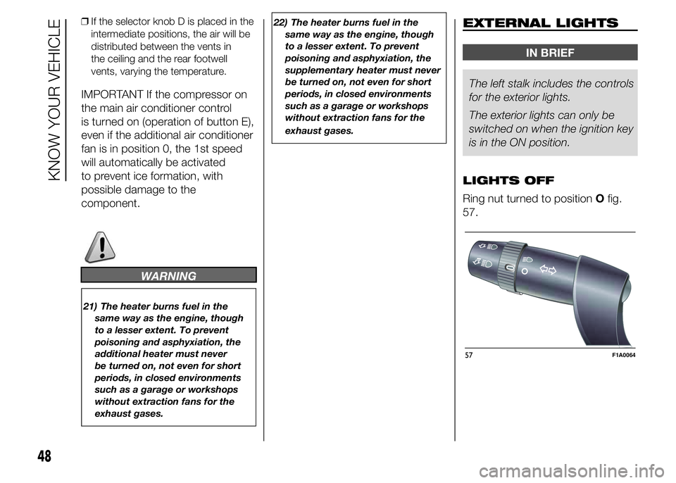
Ring nut turned to positionOfig.
57.
57F1A0064
48
KNOW YOUR VEHICLE
❒If the selector knob D is placed in the
intermediate positions, the air will be
distributed between the vents in
the ceiling and the rear footwell
vents, varying the temperature.
Page 67 of 367
FUEL CUT-OFF
SWITCH
The vehicle is fitted with a safety
switch that, in the event of a crash,
comes into operation by cutting
off the fuel supply and turning
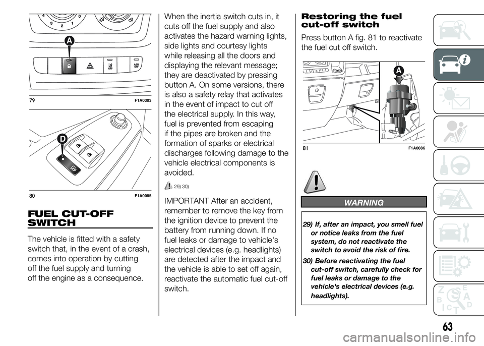
off the engine as a consequence.When the inertia switch cuts in, it
cuts off the fuel supply and also
activates the hazard warning lights,
side lights and courtesy lights
while releasing all the doors and
displaying the relevant message;
they are deactivated by pressing
button A. On some versions, there
is also a safety relay that activates
in the event of impact to cut off
the electrical supply. In this way,
fuel is prevented from escaping
if the pipes are broken and the
formation of sparks or electrical
discharges following damage to the
vehicle electrical components is
avoided.
29) 30)
IMPORTANT After an accident,
remember to remove the key from
the ignition device to prevent the
battery from running down. If no
fuel leaks or damage to vehicle's
electrical devices (e.g. headlights)
are detected after the impact and
the vehicle is able to set off again,
reactivate the automatic fuel cut-off
switch.Restoring the fuel
cut-off switch
Press button A fig. 81 to reactivate
the fuel cut off switch.WARNING
29) If, after an impact, you smell fuel
or notice leaks from the fuel
system, do not reactivate the
switch to avoid the risk of fire.
30) Before reactivating the fuel
cut-off switch, carefully check for
fuel leaks or damage to the
vehicle's electrical devices (e.g.
headlights).
79F1A0303
80F1A0085
81F1A0086
63
Page 93 of 367
TPMS (Tyre
Pressure
Monitoring System)
(for versions/markets, where
provided)
69) 70) 71) 72) 73) 74) 75) 76) 77)
DESCRIPTION
The tyre pressure monitoring
system (TPMS) warns the driver of
low tyre pressure on the basis of
the cold inflation pressure
prescribed for the vehicle.
Changes in outside temperature
may cause tyre pressure to vary.
This means that a decrease in the
outside temperature corresponds
to a decrease in the tyre pressure.
Tyre pressure must always be
adjusted according to the cold
inflation pressure. Cold tyre inflation
pressure is the tyre pressure after
letting the vehicle stand for at least
three hours or a travel shorter
than 1.6 km after an interval of
three hours.
The cold tyre inflation pressure
must not exceed the maximum
inflation pressure value printed on
the side of the tyre.The tyre pressure also increases
while driving the vehicle: this is
a normal condition and does not
require any adjustment of the
pressure.
The TPMS continues to advise the
driver of the low tyre pressure
condition until this is corrected; the
warning continues until the
pressure corresponds or exceeds
the pressure prescribed for the cold
tyres. When the tyre low pressure
control warning light
switches on
constantly, the inflation pressure
must be adjusted until it reaches
the pressure prescribed for cold
tyres. After the automatic update of
the system, the tyre pressure
control warning light switches off.
You may need to drive the vehicle
for about 20 minutes at a speed
higher than 20 km/h to allow the
TPMS to receive this information.NOTE
❒The TPMS does not replace the
normal tyre maintenance service and
does not indicate any fault in a tyre.
❒Therefore, the TPMS should not be
used as pressure switch while
adjusting the tyre inflation pressure.
❒Driving with insufficient tyre pressure
causes their overheating and can
result in tyre failure. The low inflation
pressure reduces fuel efficiency
and tyre tread life and may also affect
handling and braking performance
of the vehicle.
❒The TPMS does not replace the
correct tyre maintenance. It is up to
the driver to maintain the correct tyre
pressure level measuring it with a
suitable pressure switch. This is
necessary even if the decrease in the
inflation pressure value does not
cause the tyre pressure control
warning light to switch on.
❒The TPMS warns the driver of any
condition of insufficient tyre pressure
If this drops below the insufficient
pressure limit for any reason including
low temperature and normal
pressure loss of the tyre.
❒The seasonal temperature changes
affect tyre pressure.
89
Page 95 of 367
IMPORTANT
INFORMATION
WARNING
69) The TPMS is optimised for the
original tyres and wheels
provided. TPMS pressures and
alerts have been defined
according to the size of the tyres
mounted on the vehicle. Using
equipment with different size,
type or kind may cause irregular
system operation or sensor
damage. Non-original spare
wheels can damage the sensor.
Do not use tyre sealant or
balancing weights if the vehicle is
equipped with TPMS as these
may damage the sensors.
70) If the system signals a pressure
decrease on a specific tyre, it is
recommended to check the
pressure on all four tyres.
71) TPMS does not relieve the driver
from the obligation to check the
tyre pressure every month; it is
not even to be considered a
replacing system for maintenance
or a safety system.72) Tyre pressure must be checked
with tyres cold. Should it become
necessary for whatever reason
to check pressure with warm
tyres, do not reduce pressure
even if it is higher than the
prescribed value, but repeat the
check when tyres are cold.
73) The TPMS cannot indicate
sudden tyre pressure drops (for
example when a tyre bursts).
In this case, stop the car, braking
with caution and avoiding abrupt
steering.
74) The system only warns that the
tyre pressure is low: it is not able
to inflate them.
75) An insufficient tyre inflation
increases fuel consumption,
reduces the tread duration and
may affect the capacity of driving
safely.
76) Always refit the valve stem cap
after inspecting or adjusting tyre
pressure. This prevents dampness
or dirt from entering the valve
stem and thus the pressure
control sensor from being
damaged.77) The tyre repair kit (Fix&Go)
provided with the car (for
versions/markets, where
provided) is compatible with the
TPMS sensors; using sealants not
equivalent with that in the original
kit may adversely affect its
operation. If sealants not
equivalent with the original one
are used, it is recommended to
have the TPMS sensor operation
checked by a qualified repair
centre.
91