sensor FIAT DUCATO 2016 Owner handbook (in English)
[x] Cancel search | Manufacturer: FIAT, Model Year: 2016, Model line: DUCATO, Model: FIAT DUCATO 2016Pages: 387, PDF Size: 20.76 MB
Page 94 of 387
72) Tyre pressure must be checked
with tyres cold. Should it become
necessary for whatever reason
to check pressure with warm
tyres, do not reduce pressure
even if it is higher than the
prescribed value, but repeat the
check when tyres are cold.
73) The TPMS cannot indicate
sudden tyre pressure drops (for
example when a tyre bursts).
In this case, stop the car, braking
with caution and avoiding abrupt
steering.
74) The system only warns that the
tyre pressure is low: it is not able
to inflate them.
75) An insufficient tyre inflation
increases fuel consumption,
reduces the tread duration and
may affect the capacity of driving
safely.
76) Always refit the valve stem cap
after inspecting or adjusting tyre
pressure. This prevents dampness
or dirt from entering the valve
stem and thus the pressure
control sensor from being
damaged.77) The tyre repair kit (Fix&Go)
provided with the car (for
versions/markets, where
provided) is compatible with the
TPMS sensors; using sealants not
equivalent with that in the original
kit may adversely affect its
operation. If sealants not
equivalent with the original one
are used, it is recommended to
have the TPMS sensor operation
checked by a qualified repair
centre.DRIVING ADVISOR
(lane crossing warning)
(for versions/markets, where provided)
82) 79) 80)
The Driving Advisor is a warning system
that notifies the driver if he/she crosses
the lane because he/she has been
distracted.
A video sensor, fitted on the windscreen
near the interior rear view mirror,
detects the lane demarcation lines and
the position of the car in relation to
them.
IMPORTANT On cars with Driving
Advisor, it is advisable to contact a Fiat
Dealership should the windscreen
need to be replaced. If the repair is
carried out at a specialist window
replacement centre, it is still necessary
to go to a Fiat Dealership to have the
camera calibrated.
90
KNOW YOUR VEHICLE
Page 101 of 387
IMPORTANT
INFORMATION
IMPORTANT In some circumstances,
such as with ice, snow or mud on
the surface of the camera, its sensitivity
may be reduced.
IMPORTANT If the rear doors need to
be re-painted after the repairs, make
sure the paint does not get in contact
with the plastic support of the camera.
IMPORTANT When parking, take the
utmost care over obstacles that may be
above or under the camera range.
WARNING
81) The responsibility for parking
and other manoeuvres is always
and in any case charged to the
driver. While carrying out these
manoeuvres, always make sure
that no people (especially
children) or animals are in the
area concerned. The camera is an
aid for the driver, but the driver
must never allow his/her attention
to lapse during potentially
dangerous manoeuvres, even
those executed at low speeds.
Always keep a slow speed, so as
to promptly brake in the case
of obstacles.
IMPORTANT
9) It is vital, for correct operation,
that the camera is always kept
clean and free from mud, dirt,
snow or ice. Be careful not to
scratch or damage the camera
while cleaning it. Avoid using dry,
rough or hard cloths. The camera
must be washed using clean
water, with the addition of car
shampoo if necessary. In washing
stations which use steam or
high-pressure jets, clean the
camera quickly, keeping the
nozzle more than 10 cm away
from the sensors. Do not apply
stickers to the camera.
97
Page 102 of 387
TRAFFIC SIGN
RECOGNITION
(for versions/markets, where provided)
78) 83) 84) 85)
10) 11) 12) 13) 14) 15) 16)
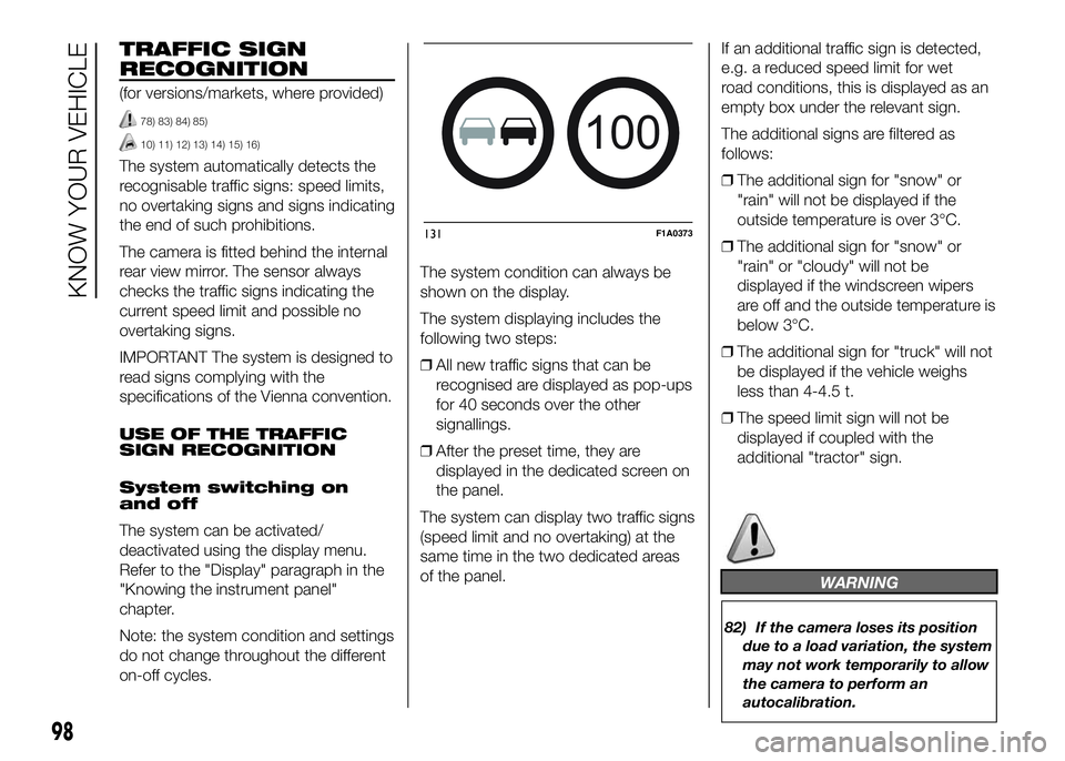
The system automatically detects the
recognisable traffic signs: speed limits,
no overtaking signs and signs indicating
the end of such prohibitions.
The camera is fitted behind the internal
rear view mirror. The sensor always
checks the traffic signs indicating the
current speed limit and possible no
overtaking signs.
IMPORTANT The system is designed to
read signs complying with the
specifications of the Vienna convention.
USE OF THE TRAFFIC
SIGN RECOGNITION
System switching on
and off
The system can be activated/
deactivated using the display menu.
Refer to the "Display" paragraph in the
"Knowing the instrument panel"
chapter.
Note: the system condition and settings
do not change throughout the different
on-off cycles.The system condition can always be
shown on the display.
The system displaying includes the
following two steps:
❒All new traffic signs that can be
recognised are displayed as pop-ups
for 40 seconds over the other
signallings.
❒After the preset time, they are
displayed in the dedicated screen on
the panel.
The system can display two traffic signs
(speed limit and no overtaking) at the
same time in the two dedicated areas
of the panel.If an additional traffic sign is detected,
e.g. a reduced speed limit for wet
road conditions, this is displayed as an
empty box under the relevant sign.
The additional signs are filtered as
follows:
❒The additional sign for "snow" or
"rain" will not be displayed if the
outside temperature is over 3°C.
❒The additional sign for "snow" or
"rain" or "cloudy" will not be
displayed if the windscreen wipers
are off and the outside temperature is
below 3°C.
❒The additional sign for "truck" will not
be displayed if the vehicle weighs
less than 4-4.5 t.
❒The speed limit sign will not be
displayed if coupled with the
additional "tractor" sign.
WARNING
82) If the camera loses its position
due to a load variation, the system
may not work temporarily to allow
the camera to perform an
autocalibration.
100
131F1A0373
98
KNOW YOUR VEHICLE
Page 103 of 387
83) The system only detects the
preset traffic signs. If the
minimum visibility conditions and
distance from the sign are met
it can detect all traffic signs.
84) The system is a driving
assistance system but it does not
relieve the driver of the
responsibility of driving with due
attention and diligence in
compliance with the laws in force.
85) When the system is active, the
driver is responsible for
controlling the vehicle and
monitoring the system, and must
intervene as appropriate if
necessary.
IMPORTANT
10) If the sensor is blocked, the
system may not work.
11) In the case of low temperatures
or harsh weather conditions, the
system may not work.
12) Rain, snow, splashes and strong
light contrast may influence the
sensor.13) Do not repair the area of the
windscreen directly surrounding
the sensor.
14) If the vehicle is equipped with a
non-genuine suspension kit, the
system may not work correctly.
15) Always use genuine spare parts
when replacing the bulbs of the
headlights. Other bulbs may
reduce the system performance.
16) Clean the windscreen from
foreign matters such as bird
droppings, insects, snow or ice.
EOBD SYSTEM
The EOBD system (European On Board
Diagnosis) allows continuous diagnosis
of emission-related components on
the vehicle to be made.
It also alerts the driver, by turning on
the
warning light in the instrument
panel (together with relevant message
in the multifunction display, for
versions/markets where provided) when
these components are no longer in
peak condition (see “Warning lights and
messages” paragraph).
The aim of the system is to:
❒monitor system efficiency;
❒indicate an increase in emissions due
to vehicle malfunction;
❒indicate the need to replace
components which have
deteriorated.
The system also has a connector that
can be interfaced with appropriate
equipment, which makes it possible to
read the error codes stored in the
control unit together with a series of
specific parameters for engine
operation and diagnosis. This check
can also be carried out by traffic control
authorities.
99
Page 104 of 387
IMPORTANT After eliminating the
failure, to check the system completely,
Fiat Dealerships run a bench test and,
if necessary, road tests which may
also call for a long journey.PARKING SENSORS
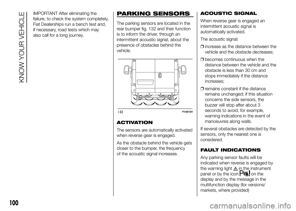
The parking sensors are located in the
rear bumper fig. 132 and their function
is to inform the driver, through an
intermittent acoustic signal, about the
presence of obstacles behind the
vehicle.
ACTIVATION
The sensors are automatically activated
when reverse gear is engaged.
As the obstacle behind the vehicle gets
closer to the bumper, the frequency
of the acoustic signal increases.ACOUSTIC SIGNAL
When reverse gear is engaged an
intermittent acoustic signal is
automatically activated.
The acoustic signal:
❒increase as the distance between the
vehicle and the obstacle decreases;
❒becomes continuous when the
distance between the vehicle and the
obstacle is less than 30 cm and
stops immediately if the distance
increases;
❒remains constant if the distance
remains unchanged; if this situation
concerns the side sensors, the
buzzer will stop after about 3
seconds to avoid, for example,
warning indications in the event of
manoeuvres along walls.
If several obstacles are detected by the
sensors, only the nearest one is
considered.
FAULT INDICATIONS
Any parking sensor faults will be
indicated when reverse is engaged by
the warning light
in the instrument
panel or by the icon
on the
display and by the message in the
multifunction display (for versions/
markets, where provided)
132F1A0134
100
KNOW YOUR VEHICLE
Page 105 of 387
OPERATION WITH
TRAILER
Parking sensor operation is
automatically deactivated when the
electric cable plug of the trailer is
inserted into the vehicle tow hook
socket.
The sensors are automatically
reactivated when the trailer's cable plug
is removed.
17)
86)
IMPORTANT If you wish to leave the
tow hook fitted without towing a trailer,
it is advisable to contact a Fiat
Dealership for the relevant system
update operations because the tow
hook could be detected as an obstacle
by the central sensors.
When using special washing equipment
such as high pressure jets or steam
cleaning, clean the sensors very quickly
keeping the jet more than 10 cm away.IMPORTANT
INFORMATION
❒Do not apply stickers to the sensors.
❒When parking, take the utmost
care over obstacles that may be
above or under the sensor.
❒Objects close to the vehicle, in
certain circumstances are not
detected and could therefore cause
damage to the vehicle or be
damaged.
The following conditions may influence
the performance of the parking
assistance system:
❒Reduced sensor sensitivity and a
reduction in the parking assistance
system performance could be due to
the presence on the surface of the
sensor of: ice, snow, mud, thick
paint.
❒The sensor may detect a non-
existent obstacle (echo noise) due to
mechanical noises, for example
when washing the vehicle, in case of
rain, strong wind, hail.
❒The signals sent by the sensors can
also be altered by the presence of
ultrasonic systems (e.g. pneumatic
brake systems or pneumatic drills)
near the vehicle.❒The performance of the parking
assistance system may also be
affected by the position of the
sensors. For example by a change in
the ride setting (caused by the wear
of the shock absorbers, suspension),
changing the tyres, overloading the
vehicle and carrying out specific
tuning operations that require the
vehicle to be lowered.
❒Detection of obstacles in the upper
part of the vehicle (particularly in the
case of vans or chassis cabs) may
not be guaranteed because the
system detects obstacles that could
strike the lower part of the vehicle.
IMPORTANT
17) The sensor must be clean of
mud, dirt, snow or ice in order for
the system to operate correctly.
Be careful not to scratch or
damage the sensors while
cleaning them. Avoid using dry,
rough or hard cloths. The sensors
must be washed using clean
water, with the addition of car
shampoo if necessary.
101
Page 106 of 387
WARNING
86) The responsibility for parking
and other dangerous manoeuvres
always and in every case lies
with the driver. While carrying out
these manoeuvres, always make
sure that no people (especially
children) or animals are in the
area concerned. The parking
sensors are used to assist the
driver, who must never allow his
attention to lapse during
potentially dangerous
manoeuvres, even those executed
at low speeds.
START&STOP
SYSTEM
IN BRIEF
The Start&Stop device automatically
stopsthe engine each time the
vehicle is stationary and starts it
again when the driver wants to move
off. This improves the efficiency of
the vehicle by reducing fuel
consumption, the emission of harmful
gases and noise pollution.
OPERATING MODES
Engine stopping mode
WITH MANUAL GEARBOX
With the vehicle stationary, the engine
stops with the gearbox in neutral and
the clutch pedal released.
NoteThe engine can only be stopped
automatically after exceeding a speed
of about 10 km/h, to prevent the engine
from being repeatedly stopped when
driving at walking pace.
Engine stopping is signalled by the
icon on the display.Engine restarting mode
WITH MANUAL GEARBOX
Depress the clutch pedal to restart the
engine.
MANUAL ACTIVATION
AND DEACTIVATION OF
THE SYSTEM
To activate/deactivate the system
manually, press the
fig. 133 button
on the dashboard control trim.
Start&Stop system
activation
A message will appear on the display
when the Start&Stop system is
activated. In this condition, the LED on
the
button is off.
Start&Stop system
deactivation
A message will appear on the display
when the Start&Stop system is
deactivated.
The LED on the
button is on when
the system is deactivated.
102
KNOW YOUR VEHICLE
Page 108 of 387
"ENERGY SAVING"
FUNCTION
(for versions/markets, where provided)
If, after the engine has been
automatically restarted, the driver does
not take any action for a period of
about 3 minutes, the Start&Stop
system will definitively stop the engine
to avoid fuel consumption. The engine
can only be started using the key in
such cases.
NoteIn any case, it is possible to keep
the engine running by deactivating
the Start&Stop system.
IRREGULAR OPERATION
In the event of malfunction, the
Start&Stop system is deactivated. The
driver is informed about the fault
through the switching on of the
icon
together with a message on the
display. In this case, contact a Fiat
Dealership.VEHICLE INACTIVITY
In the event of vehicle inactivity, special
attention must be paid to the
disconnection of the battery power
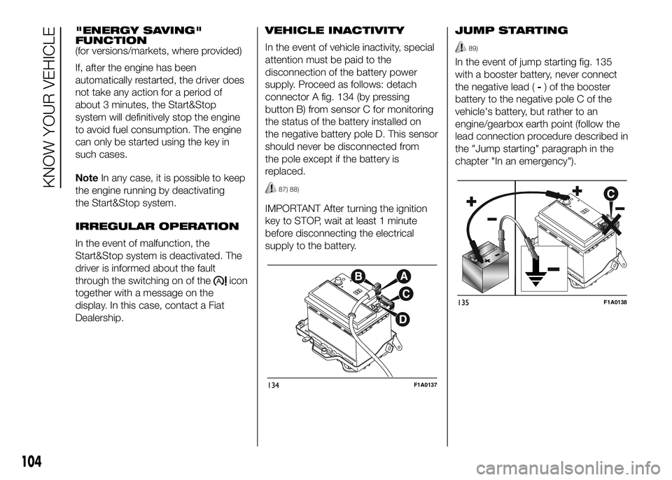
supply. Proceed as follows: detach
connector A fig. 134 (by pressing
button B) from sensor C for monitoring
the status of the battery installed on
the negative battery pole D. This sensor
should never be disconnected from
the pole except if the battery is
replaced.
87) 88)
IMPORTANT After turning the ignition
key to STOP, wait at least 1 minute
before disconnecting the electrical
supply to the battery.JUMP STARTING
89)
In the event of jump starting fig. 135
with a booster battery, never connect
the negative lead (-) of the booster
battery to the negative pole C of the
vehicle's battery, but rather to an
engine/gearbox earth point (follow the
lead connection procedure described in
the "Jump starting" paragraph in the
chapter "In an emergency").
134F1A0137
135F1A0138
104
KNOW YOUR VEHICLE
Page 119 of 387
KNOWING THE INSTRUMENT PANEL
This section of the booklet gives you all
the information you need to
understand, interpret and use the
instrument panel correctly.CONTROL PANEL AND
INSTRUMENTS ...............................116
DISPLAY ........................................122
TRIP COMPUTER ...........................131
WARNING LIGHTS AND
MESSAGES ....................................134
- LOW BRAKE FLUID/HANDBRAKE
ENGAGED .......................................... 134
- EBD FAILURE .................................. 135
- AIRBAG FAILURE ............................. 135
- SEAT BELTS NOT FASTENED .......... 136
- ENGINE COOLANT TEMPERATURE
TOO HIGH .......................................... 137
- LOW BATTERY CHARGE ................. 137
- LOW ENGINE OIL PRESSURE ......... 138
-ENGINE OIL DETERIORATED ........... 138
-INCOMPLETE DOOR/LOAD
COMPARTMENT CLOSURE ............... 139
- POWER STEERING FAILURE ........... 139
-SELF-LEVELLING SUSPENSION
FAILURE ............................................. 139
- INJECTION/EOBD SYSTEM
FAILURE ............................................. 141
-UREA INJECTION SYSTEM FAILURE
............................................................ 142
- ABS FAILURE ................................... 142
-FUEL RESERVE ................................ 143
-GLOW PLUG PREHEATING / GLOW
PLUG PREHEATING FAILURE ............ 143
-INDICATION OF DIESEL EMISSIONS
ADDITIVE LOW LEVEL (UREA) ........... 144
-VEHICLE PROTECTION SYSTEM
FAILURE - FIAT CODE ........................ 144
- REAR FOG LIGHTS .......................... 144
- GENERAL FAILURE INDICATION ..... 145
-DPF (PARTICULATE FILTER)
CLEANING UNDERWAY ..................... 146
-WORN BRAKE PADS ........................ 147-DRIVING ADVISOR ........................... 147
- TPMS ............................................... 148
- DIPPED HEADLIGHTS ..................... 149
- FOLLOW ME HOME ........................ 149
- LEFT-HAND DIRECTION INDICATOR
............................................................ 149
- RIGHT-HAND DIRECTION
INDICATOR ........................................ 150
-FOG LIGHTS ..................................... 150
- CRUISE CONTROL .......................... 150
-SPEED LIMITER ................................ 150
- AUTOMATIC MAIN BEAM
HEADLIGHTS ..................................... 151
- MAIN BEAM HEADLIGHTS .............. 151
-"UP" FUNCTION ............................... 151
-EXTERIOR LIGHTS FAULT ................ 152
-BRAKE LIGHT FAILURE .................... 152
-MAIN BEAM AUTOMATISM FAULT ... 153
-POSSIBLE ICE ON ROAD ................. 153
-SPEED LIMIT EXCEEDED ................. 153
-SCHEDULED SERVICING ................. 153
-FUEL CUT-OFF DEVICE INERTIA
SWITCH TRIPPED .............................. 154
-PARKING SENSOR FAILURE ............ 154
-DRIVING ADVISOR SYSTEM
FAILURE ............................................. 154
-TRAFFIC SIGN RECOGNITION
FAILURE ............................................. 154
-LIMITED RANGE ............................... 154
-START&STOP SYSTEM
ACTIVATION/DEACTIVATION .............. 155
-START&STOP FAILURE .................... 155
-INDICATION OF DIESEL EMISSIONS
ADDITIVE LOW LEVEL (UREA) ........... 156
-WATER IN DIESEL FILTER (diesel
versions) ............................................. 156
115
Page 127 of 387
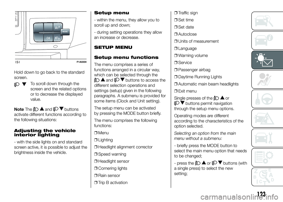
Hold down to go back to the standard
screen.
To scroll down through the
screen and the related options
or to decrease the displayed
value.
NoteThe
andbuttons
activate different functions according to
the following situations:
Adjusting the vehicle
interior lighting
- with the side lights on and standard
screen active, it is possible to adjust the
brightness inside the vehicle.Setup menu
- within the menu, they allow you to
scroll up and down;
- during setting operations they allow
an increase or decrease.
SETUP MENU
Setup menu functions
The menu comprises a series of
functions arranged in a circular way,
which can be selected through the
andbuttons to access the
different selection operations and
settings (setup) given in the following
paragraphs. A submenu is provided for
some items (Clock and Unit setting).
The setup menu can be activated
by pressing the MODE button briefly.
The menu comprises the following
functions:
❒Menu
❒Lighting
❒Headlight alignment corrector
❒Speed warning
❒Headlight sensor
❒Cornering lights
❒Rain sensor
❒Trip B activation❒Traffic sign
❒Set time
❒Set date
❒Autoclose
❒Units of measurement
❒Language
❒Warning volume
❒Service
❒Passenger airbag
❒Daytime Running Lights
❒Automatic main beam headlights
❒Exit menu
Single presses of the
or
buttons permit navigation
through the setup menu options.
Operating modes are different
according to the characteristics of the
option selected.
Selecting an option from the main
menu without a submenu:
- briefly press the MODE button to
select the main menu option that needs
to be changed;
- press the
orbuttons (with
a single press) to select the new
setting;
MODE
151F1A0304
123