steering wheel FIAT DUCATO 2016 Owner handbook (in English)
[x] Cancel search | Manufacturer: FIAT, Model Year: 2016, Model line: DUCATO, Model: FIAT DUCATO 2016Pages: 387, PDF Size: 20.76 MB
Page 11 of 387
.
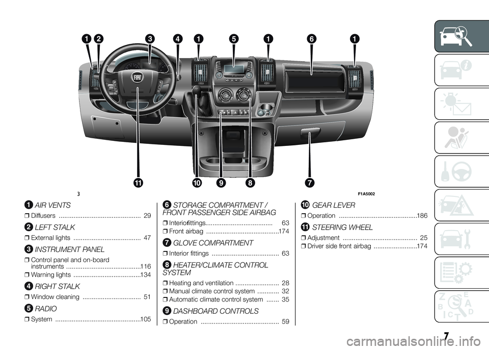
AIR VENTS
❒Diffusers ............................................. 29
LEFT STALK
❒External lights ..................................... 47
INSTRUMENT PANEL
❒Control panel and on-board
instruments .........................................116
❒Warning lights .....................................134
RIGHT STALK
❒Window cleaning ................................ 51
RADIO
❒System ...............................................105
STORAGE COMPARTMENT /
FRONT PASSENGER SIDE AIRBAG
❒Interiorfittings..................................... 63
❒Front airbag ........................................174
GLOVE COMPARTMENT
❒Interior fittings ..................................... 63
HEATER/CLIMATE CONTROL
SYSTEM
❒Heating and ventilation ........................ 28
❒Manual climate control system ............ 32
❒Automatic climate control system ....... 35
DASHBOARD CONTROLS
❒Operation ........................................... 59
GEAR LEVER
❒Operation ...........................................186
STEERING WHEEL
❒Adjustment ......................................... 25
❒Driver side front airbag ........................174
RADIO
MEDIA
PHONEINFO
A-B-C
MENU
123 4 56
3F1A5002
7
Page 13 of 387
KNOW YOUR VEHICLE
In-depth knowledge of your new vehicle
starts here.
The booklet that you are reading simply
and directly explains how it is made
and how it works.
That’s why we advise you to read it
seated comfortably on board, so that
you can see what is described here for
yourself.SYMBOLS ...................................... 11
THE FIAT CODE SYSTEM ............... 11
THE KEYS....................................... 12
ELECTRONIC ALARM..................... 14
IGNITION SWITCH .......................... 15
SEATS ............................................ 16
HEAD RESTRAINTS ........................ 24
STEERING WHEEL ......................... 25
REAR VIEW MIRRORS .................... 25
HEATING AND VENTILATION.......... 28
DIFFUSERS..................................... 29
HEATING AND VENTILATION
CONTROLS .................................... 29
MANUAL CLIMATE CONTROL
SYSTEM ......................................... 32
AUTOMATIC CLIMATE CONTROL
SYSTEM ......................................... 35
ADDITIONAL HEATER ..................... 41
INDEPENDENT ADDITIONAL
HEATER .......................................... 41
EXTERNAL LIGHTS......................... 47
WINDOW CLEANING ...................... 51
CRUISE CONTROL ......................... 54
ROOF LIGHTS ................................ 57
CONTROLS .................................... 59
FUEL CUT-OFF SWITCH ................ 62INTERIOR FITTINGS ...................... 63
TACHOGRAPH ............................... 68
SPEED BLOCK ............................... 69
SELF-LEVELLING AIR
SUSPENSION ................................. 69
DOORS ........................................... 70
ELECTRIC WINDOWS .................... 76
BONNET ......................................... 77
ROOF RACK/SKI RACK .................. 79
HEADLIGHTS.................................. 79
ABS ................................................ 80
ESC (ELECTRONIC STABILITY
CONTROL) SYSTEM ....................... 82
TRACTION PLUS SYSTEM ............. 86
TPMS (TYRE PRESSURE
MONITORING SYSTEM) ................. 87
DRIVING ADVISOR ......................... 90
REAR CAMERA (PARKVIEW®
REAR BACK UP CAMERA) ............. 95
TRAFFIC SIGN RECOGNITION ....... 97
EOBD SYSTEM............................... 98
PARKING SENSORS....................... 99
START&STOP SYSTEM ..................101
ADDITIVE FOR DIESEL EMISSIONS
ADBLUE (UREA)..............................104
9
Page 20 of 387
STEERING LOCK
Activation
When the key is at STOP, remove the
key and turn the steering wheel until
it locks.
Disengagement
Move the steering wheel slightly as you
turn the ignition key to MAR-ON
WARNING
2) If the ignition device has been
tampered with (e.g. an attempted
theft), have it checked over by a
Fiat Dealership before driving
again.
3) Always remove the key when you
leave your vehicle to prevent
someone from accidentally
operating the controls. Remember
to engage the handbrake.
Engage first gear if the vehicle is
parked uphill or reverse gear if the
vehicle is parked downhill. Never
leave children unattended in the
vehicle.4) Never extract the key while the
vehicle is moving. The steering
wheel will lock as soon as it is
turned. This also applies to cases
in which the vehicle is towed.
5) Under no circumstances should
aftermarket operations be carried
out involving steering system or
steering column modifications
(e.g. installation of anti-theft
device). This could negatively
affect performance and safety,
invalidate the warranty, cause
serious safety problems and also
result in vehicle non-compliance
with type-approval requirements.
SEATS
6)
2)
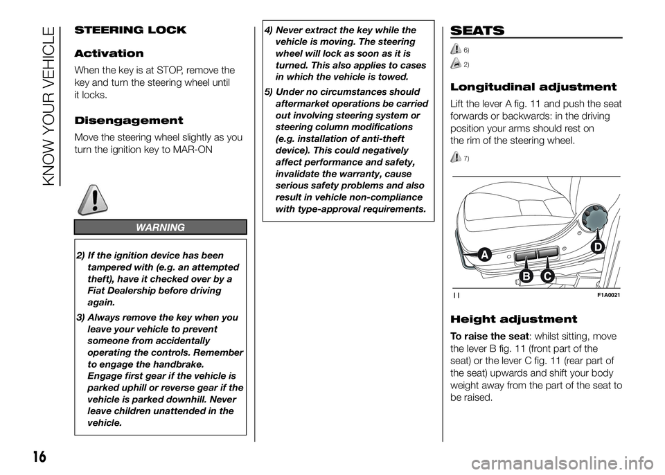
Longitudinal adjustment
Lift the lever A fig. 11 and push the seat
forwards or backwards: in the driving
position your arms should rest on
the rim of the steering wheel.
7)
Height adjustment
To raise the seat: whilst sitting, move
the lever B fig. 11 (front part of the
seat) or the lever C fig. 11 (rear part of
the seat) upwards and shift your body
weight away from the part of the seat to
be raised.
11F1A0021
16
KNOW YOUR VEHICLE
Page 29 of 387
STEERING WHEEL
The steering wheel position can be
adjusted axially.
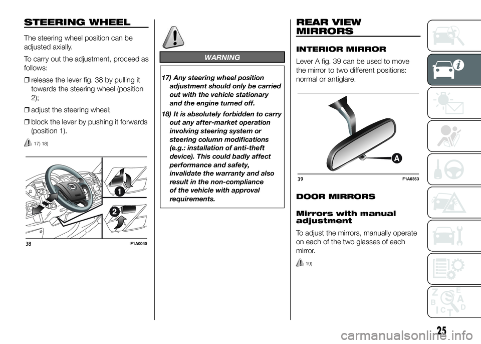
To carry out the adjustment, proceed as
follows:
❒release the lever fig. 38 by pulling it
towards the steering wheel (position
2);
❒adjust the steering wheel;
❒block the lever by pushing it forwards
(position 1).
17) 18)
WARNING
17) Any steering wheel position
adjustment should only be carried
out with the vehicle stationary
and the engine turned off.
18) It is absolutely forbidden to carry
out any after-market operation
involving steering system or
steering column modifications
(e.g.: installation of anti-theft
device). This could badly affect
performance and safety,
invalidate the warranty and also
result in the non-compliance
of the vehicle with approval
requirements.
REAR VIEW
MIRRORS
INTERIOR MIRROR
Lever A fig. 39 can be used to move
the mirror to two different positions:
normal or antiglare.
DOOR MIRRORS
Mirrors with manual
adjustment
To adjust the mirrors, manually operate
on each of the two glasses of each
mirror.
19)
38F1A0040
39F1A0353
25
Page 52 of 387
EXTERNAL LIGHTS
IN BRIEF
The left stalk includes the controls for
theexterior lights.
The exterior lights can only be
switched on when the ignition key is
in the ON position.
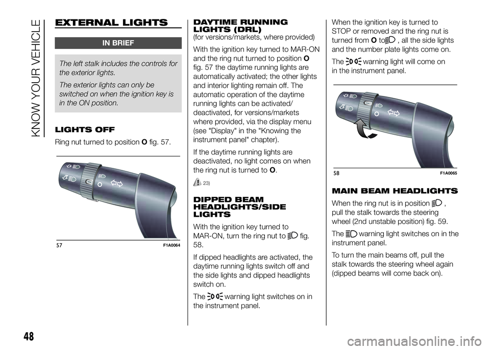
LIGHTS OFF
Ring nut turned to positionOfig. 57.DAYTIME RUNNING
LIGHTS (DRL)
(for versions/markets, where provided)
With the ignition key turned to MAR-ON
and the ring nut turned to positionO
fig. 57 the daytime running lights are
automatically activated; the other lights
and interior lighting remain off. The
automatic operation of the daytime
running lights can be activated/
deactivated, for versions/markets
where provided, via the display menu
(see "Display" in the "Knowing the
instrument panel" chapter).
If the daytime running lights are
deactivated, no light comes on when
the ring nut is turned toO.
23)
DIPPED BEAM
HEADLIGHTS/SIDE
LIGHTS
With the ignition key turned to
MAR-ON, turn the ring nut to
fig.
58.
If dipped headlights are activated, the
daytime running lights switch off and
the side lights and dipped headlights
switch on.
The
warning light switches on in
the instrument panel.When the ignition key is turned to
STOP or removed and the ring nut is
turned fromOto
, all the side lights
and the number plate lights come on.
The
warning light will come on
in the instrument panel.
MAIN BEAM HEADLIGHTS
When the ring nut is in position
,
pull the stalk towards the steering
wheel (2nd unstable position) fig. 59.
The
warning light switches on in the
instrument panel.
To turn the main beams off, pull the
stalk towards the steering wheel again
(dipped beams will come back on).
57F1A0064
58F1A0065
48
KNOW YOUR VEHICLE
Page 53 of 387
FLASHING
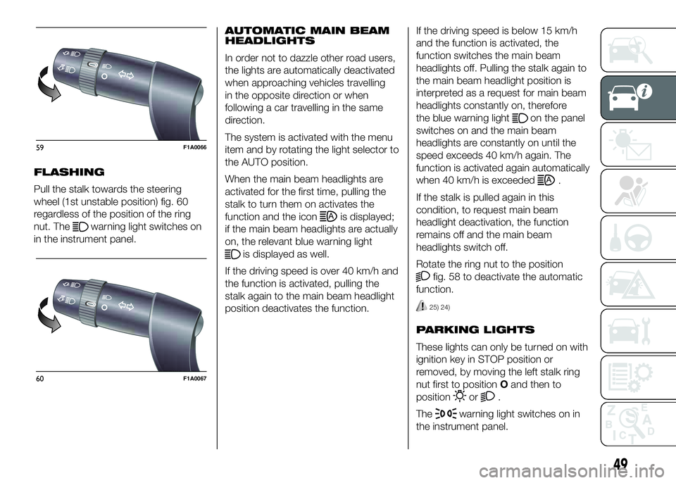
Pull the stalk towards the steering
wheel (1st unstable position) fig. 60
regardless of the position of the ring
nut. The
warning light switches on
in the instrument panel.AUTOMATIC MAIN BEAM
HEADLIGHTS
In order not to dazzle other road users,
the lights are automatically deactivated
when approaching vehicles travelling
in the opposite direction or when
following a car travelling in the same
direction.
The system is activated with the menu
item and by rotating the light selector to
the AUTO position.
When the main beam headlights are
activated for the first time, pulling the
stalk to turn them on activates the
function and the iconis displayed;
if the main beam headlights are actually
on, the relevant blue warning light
is displayed as well.
If the driving speed is over 40 km/h and
the function is activated, pulling the
stalk again to the main beam headlight
position deactivates the function.If the driving speed is below 15 km/h
and the function is activated, the
function switches the main beam
headlights off. Pulling the stalk again to
the main beam headlight position is
interpreted as a request for main beam
headlights constantly on, therefore
the blue warning light
on the panel
switches on and the main beam
headlights are constantly on until the
speed exceeds 40 km/h again. The
function is activated again automatically
when 40 km/h is exceeded
.
If the stalk is pulled again in this
condition, to request main beam
headlight deactivation, the function
remains off and the main beam
headlights switch off.
Rotate the ring nut to the position
fig. 58 to deactivate the automatic
function.
25) 24)
PARKING LIGHTS
These lights can only be turned on with
ignition key in STOP position or
removed, by moving the left stalk ring
nut first to positionOand then to
position
or.
The
warning light switches on in
the instrument panel.
59F1A0066
60F1A0067
49
Page 54 of 387
DIRECTION INDICATORS
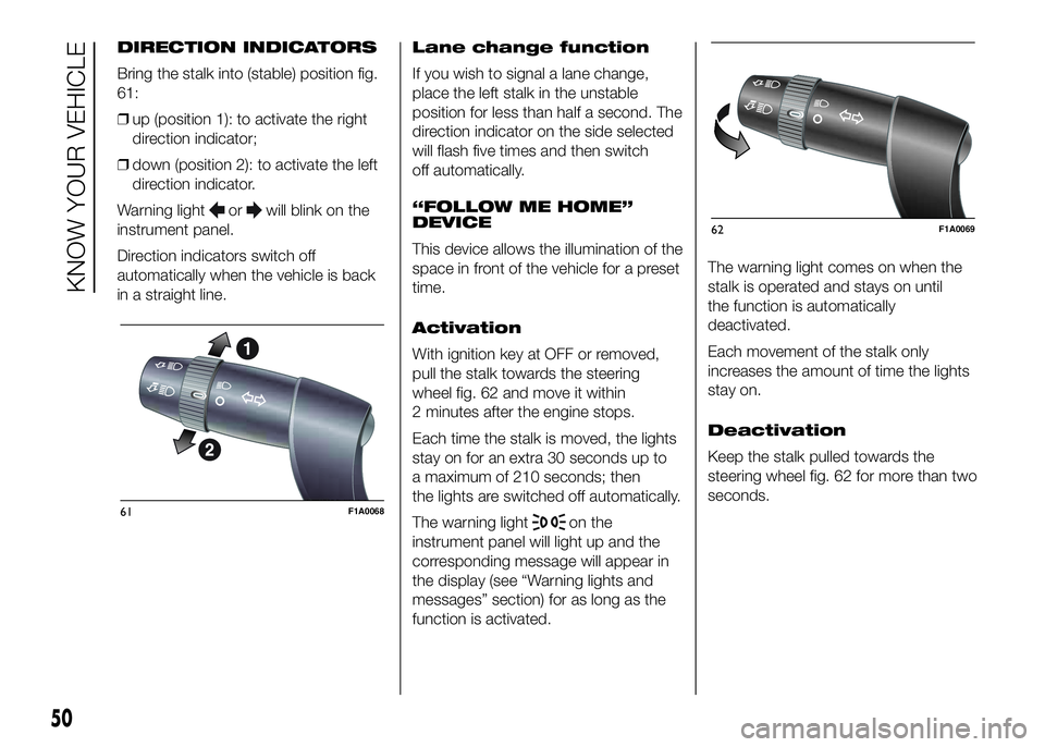
Bring the stalk into (stable) position fig.
61:
❒up (position 1): to activate the right
direction indicator;
❒down (position 2): to activate the left
direction indicator.
Warning light
orwill blink on the
instrument panel.
Direction indicators switch off
automatically when the vehicle is back
in a straight line.Lane change function
If you wish to signal a lane change,
place the left stalk in the unstable
position for less than half a second. The
direction indicator on the side selected
will flash five times and then switch
off automatically.
“FOLLOW ME HOME”
DEVICE
This device allows the illumination of the
space in front of the vehicle for a preset
time.
Activation
With ignition key at OFF or removed,
pull the stalk towards the steering
wheel fig. 62 and move it within
2 minutes after the engine stops.
Each time the stalk is moved, the lights
stay on for an extra 30 seconds up to
a maximum of 210 seconds; then
the lights are switched off automatically.
The warning light
on the
instrument panel will light up and the
corresponding message will appear in
the display (see “Warning lights and
messages” section) for as long as the
function is activated.The warning light comes on when the
stalk is operated and stays on until
the function is automatically
deactivated.
Each movement of the stalk only
increases the amount of time the lights
stay on.
Deactivation
Keep the stalk pulled towards the
steering wheel fig. 62 for more than two
seconds.61F1A0068
62F1A0069
50
KNOW YOUR VEHICLE
Page 56 of 387
WINDOW CLEANING
IN BRIEF
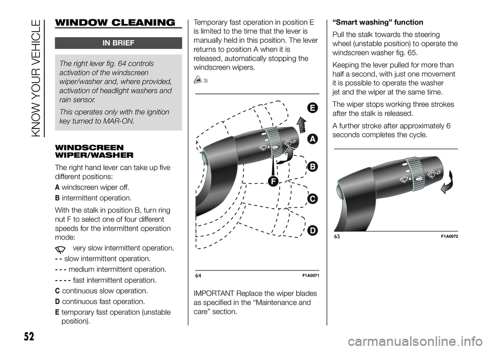
The right lever fig. 64 controls
activationof the windscreen
wiper/washer and, where provided,
activation of headlight washers and
rain sensor.
This operates only with the ignition
key turned to MAR-ON.
WINDSCREEN
WIPER/WASHER
The right hand lever can take up five
different positions:
Awindscreen wiper off.
Bintermittent operation.
With the stalk in position B, turn ring
nut F to select one of four different
speeds for the intermittent operation
mode:
very slow intermittent operation.
--slow intermittent operation.
---medium intermittent operation.
----fast intermittent operation.
Ccontinuous slow operation.
Dcontinuous fast operation.
Etemporary fast operation (unstable
position).Temporary fast operation in position E
is limited to the time that the lever is
manually held in this position. The lever
returns to position A when it is
released, automatically stopping the
windscreen wipers.
3)
IMPORTANT Replace the wiper blades
as specified in the “Maintenance and
care” section.“Smart washing” function
Pull the stalk towards the steering
wheel (unstable position) to operate the
windscreen washer fig. 65.
Keeping the lever pulled for more than
half a second, with just one movement
it is possible to operate the washer
jet and the wiper at the same time.
The wiper stops working three strokes
after the stalk is released.
A further stroke after approximately 6
seconds completes the cycle.
64F1A0071
65F1A0072
52
KNOW YOUR VEHICLE
Page 86 of 387
57) If the space-saver wheel (for
versions/markets, where
provided) is used, the ABS keeps
operating. Always remember
that the space-saver wheel, being
smaller than the original wheel,
provides less grip.ESC (Electronic
Stability Control)
SYSTEM
(for versions/markets, where provided)
The ESC system improves the
directional control and stability of the
vehicle in various driving conditions.
The ESC system corrects the vehicle’s
understeer and oversteer, distributing
the brake force on the appropriate
wheels. The torque supplied by the
engine can also be reduced in order to
maintain control of the vehicle.
The ESC system uses the sensors in
the vehicle to determine the trajectory
required by the driver through steering
and compares it with the real trajectory
of the vehicle. When the real trajectory
deviates from the desired trajectory, the
ESC system intervenes to counter the
car’s understeer or oversteer.
❒Oversteer: occurs when the vehicle is
turning more than it should according
to the angle of the steering wheel.
❒Understeer: occurs when the vehicle
is turning less than it should
according to the angle of the steering
wheelThe ESC system also includes the
following subsystems:
❒Hill Holder
❒ASR
❒HBA
❒ERM
❒HDC
58) 59) 60)
SYSTEM INTERVENTION
This is signalled by the flashing of
warning light
in the instrument panel,
to inform the driver that the vehicle is
in critical stability and grip conditions.
SYSTEM ACTIVATION
The ESC system switches on
automatically when the engine is
started and cannot be switched off.
82
KNOW YOUR VEHICLE
Page 88 of 387
When travelling on snowy roads with
snow chains, it may be helpful to turn
the ASR off: in fact, in these conditions,
the driving wheels slipping when
moving off gives you better traction.
HBA SYSTEM
(Hydraulic Brake Assist)
The HBA system is designed to
improve the vehicle’s braking capacity
during emergency braking. The system
detects emergency braking by
monitoring the speed and strength with
which the brake pedal is pressed,
thereby applying the optimal brake
pressure.
This can reduce the braking distance:
the HBA system therefore completes
the ABS.
Maximum assistance from the HBA
system is obtained by pressing the
brake pedal very quickly. In addition,
the brake pedal must be pressed
continuously during braking, avoiding
intermittent presses, to benefit from the
system.
Do not reduce pressure on the brake
pedal until braking is not necessary
anymore.
The HBA system is deactivated when
the brake pedal is released.
63) 64) 65)
ERM ELECTRONIC ROLLOVER
MITIGATION SYSTEM
(Electronic Rollover Mitigation)
The system monitors the tendency of
the wheels to rise from the ground if the
driver performs extreme manoeuvres
like quick steering to avoid an obstacle,
especially in poor road conditions.
If these conditions occur, the system
intervenes on the brakes and engine
power to reduce the possibility that the
wheels are raised from the ground.
It is not possible to avoid the tendency
to roll over if this is due to reasons
such as driving on high side gradients,
collision with objects or other vehicles.
66)
HILL DESCENT CONTROL
(HDC) SYSTEM
It is an integral part of the ESC and is
aimed at keeping the vehicle at a
constant speed during a descent,
operating autonomously on the brakes
in various ways at the same time. In this
way the vehicle stability and completely
safe driving are guaranteed, above all
in poor grip conditions and/or steep
descents.
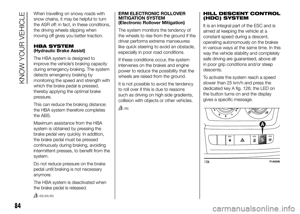
To activate the system reach a speed
slower than 25 km/h and press the
dedicated key A fig. 126; the LED on
the button turns on and the display
gives a specific message.
126F1A0300
84
KNOW YOUR VEHICLE