display FIAT DUCATO 244 2002 3.G Connect NavPlus Manual
[x] Cancel search | Manufacturer: FIAT, Model Year: 2002, Model line: DUCATO 244, Model: FIAT DUCATO 244 2002 3.GPages: 246, PDF Size: 3.39 MB
Page 218 of 246
CONNECT Nav+
217
“Draw RDS TMC”
This option is used to activate or de-
activate icon representation on the
map of RDS TMC categories of events
(“NO”, “Traffic”, “Weather”, “Info”).
In order to deactivate the icon rep-
resentation, select and confirm “NO”,
to activate it, select and confirm one
of the categories from the list. Only
one category may be represented on
the map at a time.
“Draw areas”
When this function is selected, the
following map representation options
are obtained:
– NO (representation with street,
rivers, etc.)
– 2D (representation with coloured
segments and polygons)
– 3D (three-dimensional represen-
tation).“OK”
In order to activate the new setting,
select and confirm “OK” with the
knob22-fig. 1conversely, press the
“ESC” key 23-fig. 1to return to the
previous display and keep the previous
settings.
ROUTE OPTIONS
When selecting this function on the
navigation menu third page, a new
page is obtained to enter the route cal-
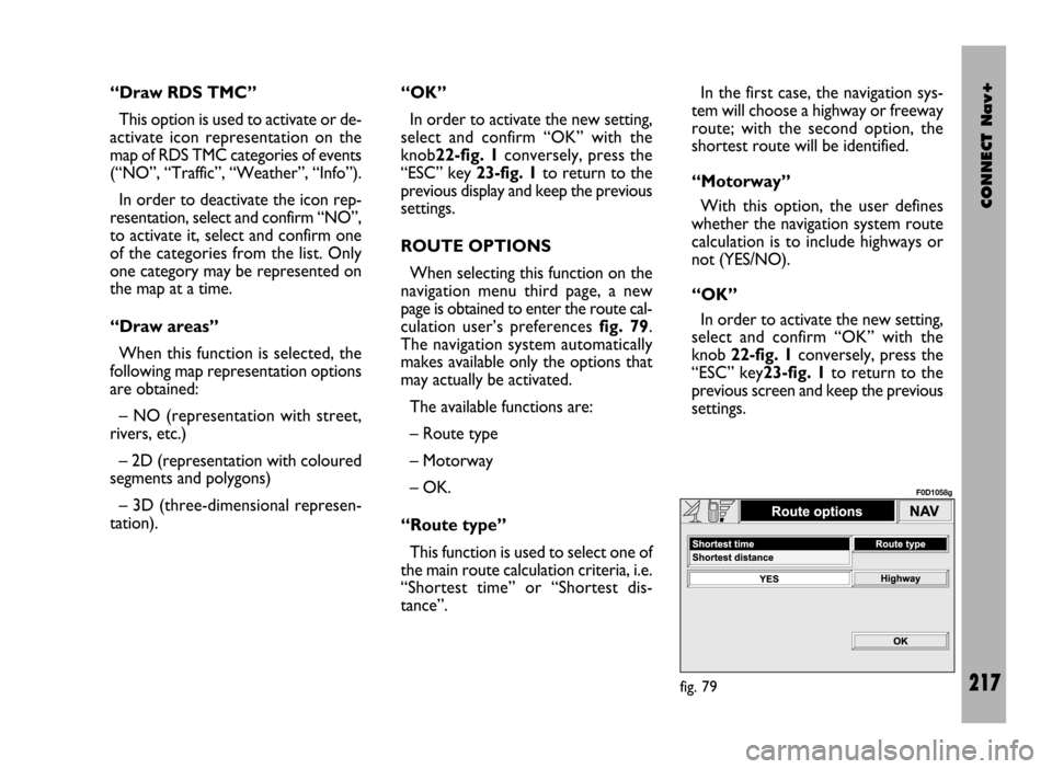
culation user’s preferences fig. 79.
The navigation system automatically
makes available only the options that
may actually be activated.
The available functions are:
– Route type
– Motorway
– OK.
“Route type”
This function is used to select one of
the main route calculation criteria, i.e.
“Shortest time” or “Shortest dis-
tance”. In the first case, the navigation sys-
tem will choose a highway or freeway
route; with the second option, the
shortest route will be identified.
“Motorway”
With this option, the user defines
whether the navigation system route
calculation is to include highways or
not (YES/NO).
“OK”
In order to activate the new setting,
select and confirm “OK” with the
knob 22-fig. 1conversely, press the
“ESC” key23-fig. 1to return to the
previous screen and keep the previous
settings.
fig. 79
F0D1058g
Page 219 of 246
CONNECT Nav+
218
GENERAL
INFORMATION
To access the on-board computer
screen, press the “TRIP” key 21-fig. 1;
to go back to the MAIN screen press
key 23-fig. 1.
The on-board computer provides a
series of helpful data relevant to the
last path selected through the NAV
function (see “Navigator” section).
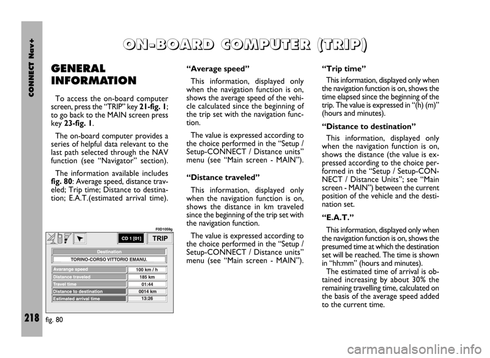
The information available includes
fig. 80: Average speed, distance trav-
eled; Trip time; Distance to destina-
tion; E.A.T.(estimated arrival time).
O O
N N
- -
B B
O O
A A
R R
D D
C C
O O
M M
P P
U U
T T
E E
R R
( (
T T
R R
I I
P P
) )
“Average speed”
This information, displayed only
when the navigation function is on,
shows the average speed of the vehi-
cle calculated since the beginning of
the trip set with the navigation func-
tion.
The value is expressed according to
the choice performed in the “Setup /
Setup-CONNECT / Distance units”
menu (see “Main screen - MAIN”).
“Distance traveled”
This information, displayed only
when the navigation function is on,
shows the distance in km traveled
since the beginning of the trip set with
the navigation function.
The value is expressed according to
the choice performed in the “Setup /
Setup-CONNECT / Distance units”
menu (see “Main screen - MAIN”).“Trip time”
This information, displayed only when
the navigation function is on, shows the
time elapsed since the beginning of the
trip. The value is expressed in “(h) (m)”
(hours and minutes).
“Distance to destination”
This information, displayed only
when the navigation function is on,
shows the distance (the value is ex-
pressed according to the choice per-
formed in the “Setup / Setup-CON-
NECT / Distance Units”; see “Main
screen - MAIN”) between the current
position of the vehicle and the desti-
nation set.
“E.A.T.”
This information, displayed only when
the navigation function is on, shows the
presumed time at which the destination
set will be reached. The time is shown
in “hh:mm” (hours and minutes).
The estimated time of arrival is ob-
tained increasing by about 30% the
remaining travelling time, calculated on
the basis of the average speed added
to the current time.
fig. 80
F0D1059g
Page 224 of 246
CONNECT Nav+
223
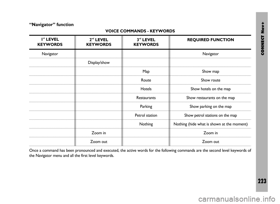
“Navigator” function
VOICE COMMANDS - KEYWORDS
1
stLEVEL
KEYWORDS
Navigator
Once a command has been pronounced and executed, the active words for the following commands are the second level keywords of
the Navigator menu and all the first level keywords.2
ndLEVEL
KEYWORDS
Display/show
Zoom in
Zoom out3rdLEVEL
KEYWORDS
Map
Route
Hotels
Restaurants
Parking
Petrol station
NothingREQUIRED FUNCTION
Navigator
Show map
Show route
Show hotels on the map
Show restaurants on the map
Show parking on the map
Show petrol stations on the map
Nothing (hide what is shown at the moment)
Zoom in
Zoom out
Page 233 of 246
CONNECT Nav+
232
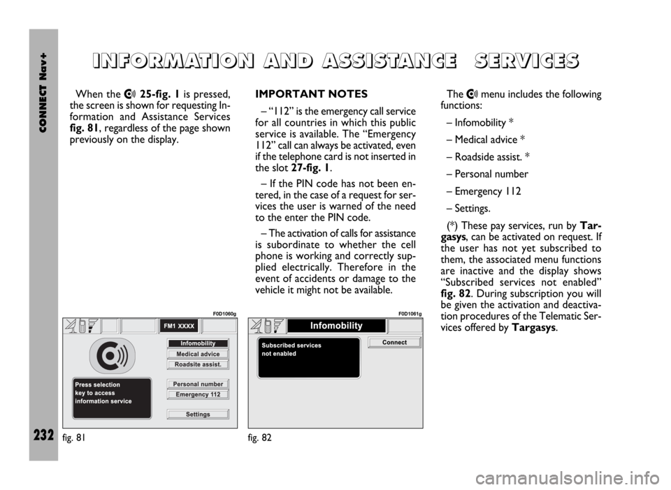
When the •25-fig. 1is pressed,
the screen is shown for requesting In-
formation and Assistance Services
fig. 81, regardless of the page shown
previously on the display.IMPORTANT NOTES
– “112” is the emergency call service
for all countries in which this public
service is available. The “Emergency
112” call can always be activated, even
if the telephone card is not inserted in
the slot 27-fig. 1.
– If the PIN code has not been en-
tered, in the case of a request for ser-
vices the user is warned of the need
to the enter the PIN code.
– The activation of calls for assistance
is subordinate to whether the cell
phone is working and correctly sup-
plied electrically. Therefore in the
event of accidents or damage to the
vehicle it might not be available.The •menu includes the following
functions:
– Infomobility *
– Medical advice *
– Roadside assist. *
– Personal number
– Emergency 112
– Settings.
(*) These pay services, run by Tar-
gasys, can be activated on request. If
the user has not yet subscribed to
them, the associated menu functions
are inactive and the display shows
“Subscribed services not enabled”
fig. 82. During subscription you will
be given the activation and deactiva-
tion procedures of the Telematic Ser-
vices offered by Targasys.
I I
N N
F F
O O
R R
M M
A A
T T
I I
O O
N N
A A
N N
D D
A A
S S
S S
I I
S S
T T
A A
N N
C C
E E
S S
E E
R R
V V
I I
C C
E E
S S
fig. 81
F0D1060g
fig. 82
F0D1061g
Page 234 of 246
CONNECT Nav+
233
“Infomobility” FUNCTION
“Connect”
Selecting “Infomobility” and con-
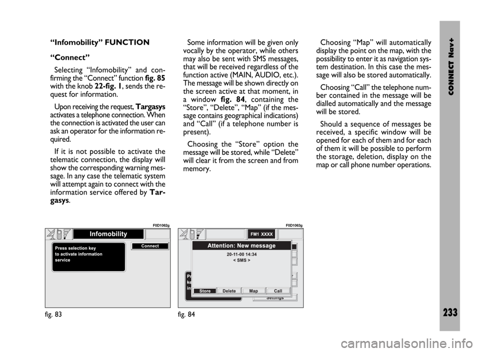
firming the “Connect” function fig. 85
with the knob 22-fig. 1, sends the re-
quest for information.
Upon receiving the request, Targasys
activates a telephone connection. When
the connection is activated the user can
ask an operator for the information re-
quired.
If it is not possible to activate the
telematic connection, the display will
show the corresponding warning mes-
sage. In any case the telematic system
will attempt again to connect with the
information service offered by Tar-
gasys.Some information will be given only
vocally by the operator, while others
may also be sent with SMS messages,
that will be received regardless of the
function active (MAIN, AUDIO, etc.).
The message will be shown directly on
the screen active at that moment, in
a window fig. 84, containing the
“Store”, “Delete”, “Map” (if the mes-
sage contains geographical indications)
and “Call” (if a telephone number is
present).
Choosing the “Store” option the
message will be stored, while “Delete”
will clear it from the screen and from
memory.Choosing “Map” will automatically
display the point on the map, with the
possibility to enter it as navigation sys-
tem destination. In this case the mes-
sage will also be stored automatically.
Choosing “Call” the telephone num-
ber contained in the message will be
dialled automatically and the message
will be stored.
Should a sequence of messages be
received, a specific window will be
opened for each of them and for each
of them it will be possible to perform
the storage, deletion, display on the
map or call phone number operations.
fig. 83
F0D1062g
fig. 84
F0D1063g
Page 235 of 246
CONNECT Nav+
234
“Select”
If they are not deleted, all the mes-
sages received are stored. The list with
all the messages can be seen in the
bottom of the display, in the screen
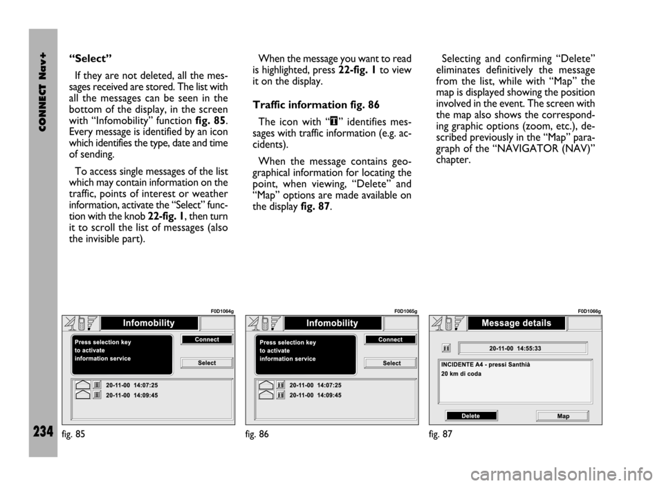
with “Infomobility” function fig. 85.
Every message is identified by an icon
which identifies the type, date and time
of sending.
To access single messages of the list
which may contain information on the
traffic, points of interest or weather
information, activate the “Select” func-
tion with the knob 22-fig. 1, then turn
it to scroll the list of messages (also
the invisible part). When the message you want to read
is highlighted, press 22-fig. 1to view
it on the display.
Traffic information fig. 86
The icon with “\” identifies mes-
sages with traffic information (e.g. ac-
cidents).
When the message contains geo-
graphical information for locating the
point, when viewing, “Delete” and
“Map” options are made available on
the display fig. 87.Selecting and confirming “Delete”
eliminates definitively the message
from the list, while with “Map” the
map is displayed showing the position
involved in the event. The screen with
the map also shows the correspond-
ing graphic options (zoom, etc.), de-
scribed previously in the “Map” para-
graph of the “NAVIGATOR (NAV)”
chapter.
fig. 85
F0D1064g
fig. 86
F0D1065g
fig. 87
F0D1066g
Page 236 of 246
CONNECT Nav+
235
Information about points
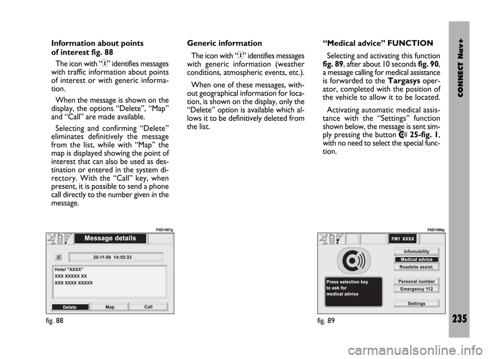
of interest fig. 88
The icon with “<” identifies messages
with traffic information about points
of interest or with generic informa-
tion.
When the message is shown on the
display, the options “Delete”, “Map”
and “Call” are made available.
Selecting and confirming “Delete”
eliminates definitively the message
from the list, while with “Map” the
map is displayed showing the point of
interest that can also be used as des-
tination or entered in the system di-
rectory. With the “Call” key, when
present, it is possible to send a phone
call directly to the number given in the
message.Generic information
The icon with “<” identifies messages
with generic information (weather
conditions, atmospheric events, etc.).
When one of these messages, with-
out geographical information for loca-
tion, is shown on the display, only the
“Delete” option is available which al-
lows it to be definitively deleted from
the list. “Medical advice” FUNCTION
Selecting and activating this function
fig. 89, after about 10 seconds fig. 90,
a message calling for medical assistance
is forwarded to the Targasysoper-
ator, completed with the position of
the vehicle to allow it to be located.
Activating automatic medical assis-
tance with the “Settings” function
shown below, the message is sent sim-
ply pressing the button
•25-fig. 1,
with no need to select the special func-
tion.
fig. 88
F0D1067g
fig. 89
F0D1068g
Page 239 of 246
CONNECT Nav+
238
CALLS FOR MEDICAL
ADVICE OR ROADSIDE
ASSISTANCE
During the forwarding of a call for as-
sistance to the operating centre, any
other operations activated are inter-
rupted and the volume of any audio
sources (except the phone) is muted.
These conditions will be maintained as
long as the call for assistance is active,
with the corresponding screen on the
display.
If a phone call is received while for-
warding a request for assistance, the
corresponding alert will not be shown
on the display but the ringer will ring.
If the user decides to accept the call
and briefly presses the
òkey 13-
fig. 1, the assistance call screen goes
off the display.IMPORTANTThe call for assis-
tance is always forwarded; however, if
the you accept the incoming call, the
Targasysoperator might have diffi-
culty in contacting you since the num-
ber could be busy.
When the call has been sent, the dis-
play shows the corresponding call for-
warded message for about 4 seconds.If for any reason the call for assis-
tance cannot be sent, the display
shows a warning message and the user
is then asked if he wants to activate a
phone call in any case (*) to the op-
erating centre to avail of the service
required, even if in this case the op-
erating centre will no longer be able
to locate the vehicle.
(*) The call is normally made using
the toll-free number, while it is at the
user’s expense if it is made in roam-
ing conditions.
Page 240 of 246
CONNECT Nav+
239
The CONNECT Nav+ can display,
when the ignition key is at MAR, the
images coming from the telecamera
set on the back of the roof, when re-
verse gear is engaged to facilitate park-
ing. This image effect is called “mir-
roring” i.e. the image appears as re-
flected by a rearview mirror. Turn
knob 22-fig. 1to adjust the display
brightness; this adjustment will be kept
also for the next reverse gear en-
gagements, until you turn the ignition
key to STOP. Each time the ignition
key is turned to MARthe display will
propose the default brightness which
corresponds to an intermediate val-
ue included within minimum and max-
imum brightness.
T T
E E
L L
E E
C C
A A
M M
E E
R R
A A
( (
w w
h h
e e
r r
e e
p p
r r
o o
v v
i i
d d
e e
d d
) )
For proper system op-
eration and image sharp-
ness, keep the telecamera
area clean.
When turning the telecamera on, the
other CONNECT Nav+ functions re-
main active “in background” (they are
not displayed), sub-functions are how-
ever kept operating. Under this con-
dition, all control keys are disabled, ex-
cluding the following:
– MAIN-DARK key 17-fig. 1only
for “dark” mode (darkening the mon-
itor);
– key •25-fig. 1;
– “SRC” key 15-fig. 1;
– key ò13-fig. 1;
– knob 22-fig. 1adjust image bright-
ness only;
– knob 16-fig. 1for setting the au-
dio volume.The different system mode condi-
tions when engaging the reverse gear
are the following:
MAIN mode
“MAIN/DARK” key 17-fig. 1dis-
abled, and also:
– with DARK active, next reverse
engagement will automatically display
the telecamera images; reverse disen-
gagement will return the system to
DARK condition;
– when the telecamera image is dis-
played, it will not be possible to acti-
vate the DARK mode (key disabled),
and also “Memorize” and “Setup” will
be inhibited.
Page 241 of 246
CONNECT Nav+
240
AUDIO mode
When the telecamera image is dis-
played, the AUDIO mode is enabled:
– “AUDIO” key 18-fig. 1disabled;
– the active source (RADIO, CD)
stays on;
– audio volume setting, knob 16-fig.
1enabled;
– “SRC” key 15-fig. 1enabled;
– station tuning disabled.
TEL mode
When the telecamera image is dis-
played, the TEL mode is enabled:
– “TEL” key 19-fig. 1disabled;
– key ò13-fig. 1enabled.INCOMING CALL WITH DISPLAYED
TELECAMERA IMAGE
When the above condition occurs,
the following takes place:
– automatic display switching to TEL
mode display;
– incoming call number display (if
available);
– briefly press the òkey 13-fig. 1to
accept the incoming call or press it at
length to refuse the call. Just after
pressing the key (with reverse en-
gaged) the display returns to display
the telecamera image and if the in-
coming call is accepted the system will
enable the communication. If during
this phase there is another incoming
call, the display will show the TEL
mode again.
FORWARDING CALL WITH DISPLAYED
TELECAMERA IMAGE
Briefly press the òkey 13-fig. 1to
obtain the following:
– disable the telecamera image;
– display the last dialled number (see
“Cellular telephone” chapter); press
again the òkey 13-fig. 1to forward
a call within 10 seconds. Pressing
“ESC” 23-fig. 1will delete the last di-
alled number and activate the window
to be used for dialling (through the key-
pad) the required telephone number;
pressing the òkey 13-fig. 1again will
forward the call;
– press ESC 23-fig. 1at length to
return to the telecamera image (with
reverse gear engaged).