navigation system FIAT DUCATO 244 2002 3.G Connect NavPlus Manual
[x] Cancel search | Manufacturer: FIAT, Model Year: 2002, Model line: DUCATO 244, Model: FIAT DUCATO 244 2002 3.GPages: 246, PDF Size: 3.39 MB
Page 162 of 246
CONNECT Nav+
161
FLEET MANAGEMENT
When choosing this function, the
CONNECT Nav+ sends automatical-
ly SMS messages (to a suitable preset
receiver, e.g. a control centre) de-
scribing the position of the vehicle
mounting the CONNECT Nav+.
SMS messages are structured as fol-
lows:
– vehicle location (latitude and lon-
gitude)
– city (only with navigation CD in-
serted; if no CD is inserted, the field
is empty)
– street (only with navigation CD in-
serted; if no CD is inserted, the field
is empty)
– time and date
– vehicle ID (number plate).Example: LT:-2.30000;LG:-2.40000; #Benevento;#
Via Basilio Giannelli;#S:30;M:20; H:19;ND:2;D:02;MH:10;Y:2001;#BR757AM;#
– press the “MAIN” button 17-fig. 1
to display the main screen;
– select and confirm “Setup” by ro-
tating and pressing the knob 22-fig. 1;
the display will show the “Com-
mands&Set” menu;
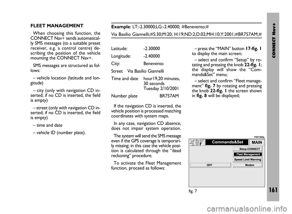
– select and confirm “Fleet manage-
ment” fig. 7by rotating and pressing
the knob 22-fig. 1the screen shown
in fig. 8will be displayed; Latitude: -2.30000
Longitude: -2.40000
City: Benevento
Street Via Basilio Giannelli
Time and date hour19,20 minutes,
30 seconds
Tuesday 2/10/2001
Number plate BR757AM
If the navigation CD is inserted, the
vehicle position is processed matching
coordinates with system maps.
In any case, navigation CD absence,
does not impair system operation.
The system will send the SMS message
even if the GPS coverage is temporari-
ly missing; in this case the vehicle posi-
tion is calculated through the “dead
reckoning” procedure.
To activate the Fleet Management
function, proceed as follows:
fig. 7
F0D1080g
Page 168 of 246

CONNECT Nav+
167
MODEM (data interface)
This function enables to connect an
external device (e.g.: portable com-
puter) to the CONNECT Nav+ that
in this case will act as a modem. To im-
plement such configuration the link be-
tween the external device and the
CONNECT Nav+ connection (to be
found in central position under the
dashboard) shall be performed using
the cable provided with the system.
The max. data transmission speed is
that provided for the cellular tele-
phone mode (TEL) and is equal to 9.6
Kbps, as established by the commu-
nication with GSM cell network.
During data transmission (modem
function on), the CONNECT Nav+
condition is the following:
– telephone mode off (TEL-OFF);
– incoming calls blocked;– call forwarding blocked;
– navigator (NAV) function can be
activated; if navigation is on data trans-
mission can be slow;
– all audio functions (radio, CD) can
be activated
– emergency call can be forwarded
by pressing •25-fig. 1.IMPORTANTThe modem func-
tion cannot be activated during a call.
IMPORTANTPress button •to
abort the modem function; the system
will restore the GSM telephone mode
for the selected function and will re-
quest to enter the PIN code; data ex-
changed during transmission will be
lost (unless data back-up have been
performed by user’s computer appli-
cations).
The modem function will not be re-
stored automatically by the system
when the emergency or service call is
over. To restore it repeat the proce-
dure from the beginning.
Page 199 of 246
CONNECT Nav+
198
GENERAL
INFORMATION
The navigator integrated in the
CONNECT Nav+ allows you to reach
the chosen destination by visual and
voice instructions. Use of the naviga-
tion system is quick, convenient, safe
and above all very flexible because it al-
lows you to call up already pro-
grammed destinations or points of ref-
erence such as hotels, monuments,
public structures, fuel stations or Fi-
at Dealerships.
The vehicle position is determined
through the GPS system (Global Posi-
tioning System) installed on the vehicle.
The GPS system is fitted with an an-
tenna and a reception module inte-
grated in the telematic system. This sys-
tem configuration dynamically process-
es the satellite signals, those from the
right and left odometer, the reversing
signal and the information of the gyro-
scope integrated in the navigation com-
puter, integrating them with the cur-
rent position of the vehicle to obtain an
“estimated vehicle point”.The signals from the right and left
odometer make it possible to deter-
mine the movement of the vehicle, the
gyroscope signal identifies any turn-
ing and the reversing sensor distin-
guishes the direction of travel.
The Fiat navigation system helps the
driver while he/ahe drives by suggest-
ing vocally and graphically the opti-
mum routing to reach the preset des-
tination.IMPORTANT NOTES
– GPS reception is difficult under
trees, among tall buildings, in multi-lev-
el car parks, tunnels and everywhere
reception of the satellite antenna may
be hindered.
– The GPS system needs about 15
minutes for activation if the vehicle
battery is disconnected.
– The GPS system needs a few min-
utes to determine the new position of
the vehicle if it is turned off and the ve-
hicle is moved with the system off (e.g.:
by breakdown van).
– In the lack of satellite information,
the system uses information from the
gyroscope and from the special sen-
sors for temporary data analysis.
– The GPS satellite aerial must not
be covered with metal or damp ob-
jects.
N N
A A
V V
I I
G G
A A
T T
O O
R R
( (
N N
A A
V V
) )
The navigation system sug-
gestions do not exempt the
driver from full responsibility due to
his driving behaviour and to com-
pliance with road and other traffic
regulations. The responsibility for
road safety always and in any case
lies with the vehicle driver.
WARNING
Page 200 of 246
CONNECT Nav+
199
The instantaneous vehicle position is
identified in the CD-ROM and shown
on the display together with the topo-
graphic characteristics of the area
memorised on the CD-ROM. Access
to data on the CD-ROM requires a
few moments waiting for the map dis-
plays.
The system constantly compares da-
ta from the speed sensor, from the re-
verse gear sensor, from the GPS an-
tenna and the gyroscope to automat-
ically compensate changes in temper-
ature, pressure or any other occur-
rence that may lead to a false position
detection in any way.
IMPORTANT NOTES
– Accurate self-adjustment of the
navigation system requires approx.
1-10 km of travel the first time and
when tyres are changed.– Continuous lack of grip at the
wheels (for example skidding on ice),
makes the system temporarily detect
an incorrect position.
The navigation system is completely
managed by the telematic system,
therefore the only operations that may
be required are replacement of the
CD-ROM to set the map of another
area or an updated map.
Access to the navigation main func-
tions is gained by short push on
“NAV” key 20-fig. 1after turning on. Long push on “NAV” key 20-fig. 1
engages the navigation system Mute
function, which will therefore no
longer provide voice instructions.
When the Mute function is on, the dis-
play shows “Nav Mute”. To turn the
Mute function off press again the
“NAV” key 20-fig. 1at length.
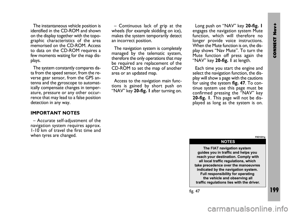
Each time you start the engine and
select the navigation function, the dis-
play will show a page with the cautions
for using the system fig. 47. To con-
tinue system use this page must be
confirmed pressing the “NAV” key
20-fig. 1. This page will not be dis-
played as long as the system is on.
fig. 47
F0D1031g
Page 201 of 246

CONNECT Nav+
200
SCREEN OPTIONS
AND FUNCTIONS
The main information and functions
provided and managed by the naviga-
tion system are:
ëGPS signal symbol which differs in
colour depending on the quality of re-
ception;
– voice and visual instructions with
indications of distance from the des-
tination and planned arrival time;
– detailed map in different colours
and with different scales to clearly
show the vehicle position, route and
destination;
– customisation of the navigation sys-
tem with possibility of entering pre-
memorised destinations with street
and street number;
– automatic memorising of the last 8
destinations;
– name of current street;– possibility to choose the route ac-
cording to personal preference;
– information on current position;
– information on arrival time;
– system diagnostics and warnings
about possible disturbances.
If the system contains a wrong CD-
ROM, an audio CD or no CD, when-
ever the system asks for the navigation
CD-ROM for route calculation or map
up-date, the insertion prompt will ap-
pear on the display.
Navigation functions are mainly con-
trolled using the knob 22-fig. 1:
– rotate the knob to access the var-
ious map zoom levels;
– press the knob to display the first
menu page;
– use the knob to select and confirm
the “Other menu” item and access the
following menu pages;
– press the knob again and the menu
page will disappear.
GRAPHIC
INSTRUCTIONS
The main navigation function page
and the MAIN page display the ma-
noeuvres to be made using arrows or
symbols.
The downward arrow represents
next manoeuvre (turn left, right,
straight on, U-turn) while the upward
arrow or the symbol on top represent
the next one. The number displayed
under the arrow indicates the vehicle
distance from the turn point.
The small arrow down on the right-
hand side of the display (on the MAIN
page) or in the top box (on the main
navigation function page) indicates the
destination direction. Next to this ar-
row the planned arrival time and the
distance still to be covered are also in-
dicated.
Page 202 of 246
CONNECT Nav+
201
VOICE
INSTRUCTIONS
The voice instructions provided by
the system guide you to your destina-
tion and suggest all manoeuvres to be
carried out in due time: in particular,
the manoeuvres is announced first and
then detailed instructions are given.
Press the “RPT” key 24-fig. 1to re-
peat the last voice instruction.
To adjust the volume of the voice in-
struction turn the knob 16-fig. 1dur-
ing voice information.
If necessary, press the “RPT” key 24-
fig. 1to repeat the voice instruction
and adjust the volume.
NAVIGATION
CD-ROM PLAYER
The navigation CD-ROM player 28-
fig. 1is located on the telematic sys-
tem front panel and it is the same used
for the audio CD. Therefore, it is not
possible to use the player for audio
and navigation CD-ROM at the same
time: however, the navigation system
can operate partially even without in-
serting the navigation CD-ROM.
In this case, when pressing key
26-fig. 1to remove the CD-ROM
with navigation function engaged (to
then insert an audio CD), the follow-
ing two cases may occur:
– the system cannot calculate the re-
quired route at present;
– the route calculated before re-
moving the navigation CD-ROM is still
valid.
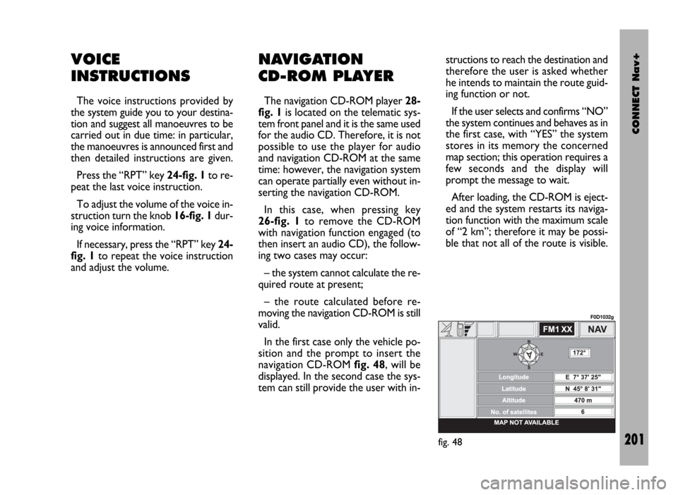
In the first case only the vehicle po-
sition and the prompt to insert the
navigation CD-ROM fig. 48, will be
displayed. In the second case the sys-
tem can still provide the user with in-structions to reach the destination and
therefore the user is asked whether
he intends to maintain the route guid-
ing function or not.
If the user selects and confirms “NO”
the system continues and behaves as in
the first case, with “YES” the system
stores in its memory the concerned
map section; this operation requires a
few seconds and the display will
prompt the message to wait.
After loading, the CD-ROM is eject-
ed and the system restarts its naviga-
tion function with the maximum scale
of “2 km”; therefore it may be possi-
ble that not all of the route is visible.
fig. 48
F0D1032g
Page 203 of 246
CONNECT Nav+
202
Moreover, navigation in these con-
ditions involves limitations and there-
fore some functions and commands
will not be available. Also information
shown on the map will be limited.
When the navigation system is no
longer able to continue destination
guidance or the vehicle is now out of
the loaded map section, the system
prompts for inserting the navigation
CD-ROM. If the user does not insert
the CD-ROM, the system returns to
the operating conditions previously
described for the first case, i.e.: dis-
playing only GPS information (vehicle
position and number of available satel-
lites) and not map information.IMPORTANT NOTES
– When entering the new CD-ROM,
the system software is automatically
up-dated to the new map material or
the new functions. During this opera-
tion, a wait message is displayed and
at the end the destination memory is
empty.
– The driver is always responsible for
compliance with the enforced traffic
regulations: any indication based on
wrong map data leading to unautho-
rised driving manoeuvres MUST NOT
be followed.
NAVIGATION SYSTEM
MENU
The system features three menu
pages that are shown on the display af-
ter selecting the navigation function
page with the “NAV” key 20-fig. 1,
pressing knob 22-fig. 1and selecting
the “Other menus” option on each
menu page.
The following pages describe the
functions that may be selected from
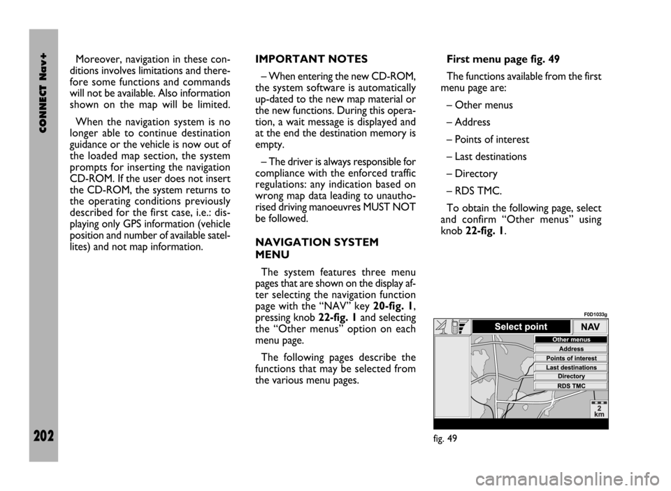
the various menu pages.First menu page fig. 49
The functions available from the first
menu page are:
– Other menus
– Address
– Points of interest
– Last destinations
– Directory
– RDS TMC.
To obtain the following page, select
and confirm “Other menus” using
knob 22-fig. 1.
fig. 49
F0D1033g
Page 205 of 246
CONNECT Nav+
204
“Place name”
The (destination) city name is en-
tered by selecting and confirming
“Place name” option in the “Address”
function submenu with the knob 22-
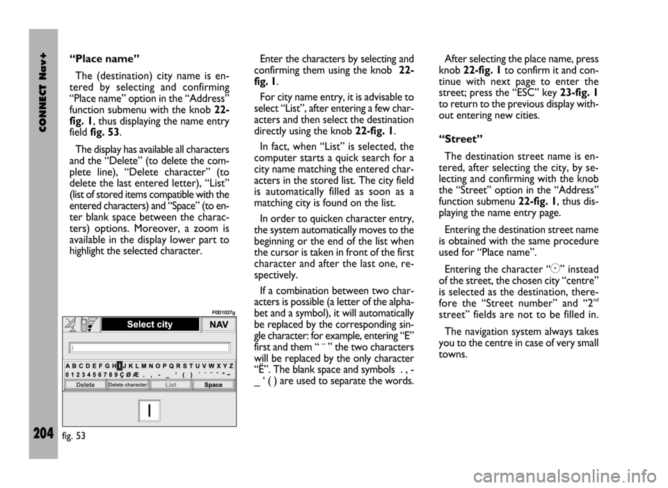
fig. 1, thus displaying the name entry
field fig. 53.
The display has available all characters
and the “Delete” (to delete the com-
plete line), “Delete character” (to
delete the last entered letter), “List”
(list of stored items compatible with the
entered characters) and “Space” (to en-
ter blank space between the charac-
ters) options. Moreover, a zoom is
available in the display lower part to
highlight the selected character.Enter the characters by selecting and
confirming them using the knob 22-
fig. 1.
For city name entry, it is advisable to
select “List”, after entering a few char-
acters and then select the destination
directly using the knob 22-fig. 1.
In fact, when “List” is selected, the
computer starts a quick search for a
city name matching the entered char-
acters in the stored list. The city field
is automatically filled as soon as a
matching city is found on the list.
In order to quicken character entry,
the system automatically moves to the
beginning or the end of the list when
the cursor is taken in front of the first
character and after the last one, re-
spectively.
If a combination between two char-
acters is possible (a letter of the alpha-
bet and a symbol), it will automatically
be replaced by the corresponding sin-
gle character: for example, entering “E”
first and them “ ¨ ” the two characters
will be replaced by the only character
“Ë”. The blank space and symbols . , -
_ ‘ ( ) are used to separate the words.After selecting the place name, press
knob 22-fig. 1to confirm it and con-
tinue with next page to enter the
street; press the “ESC” key 23-fig. 1
to return to the previous display with-
out entering new cities.
“Street”
The destination street name is en-
tered, after selecting the city, by se-
lecting and confirming with the knob
the “Street” option in the “Address”
function submenu 22-fig. 1, thus dis-
playing the name entry page.
Entering the destination street name
is obtained with the same procedure
used for “Place name”.
Entering the character “C” instead
of the street, the chosen city “centre”
is selected as the destination, there-
fore the “Street number” and “2
nd
street” fields are not to be filled in.
The navigation system always takes
you to the centre in case of very small
towns.
fig. 53
F0D1037g
Page 207 of 246
CONNECT Nav+
206
The “Enter” function is used to add
a new destination to the list contain-
ing the last 8 destinations entered and
specify its location. The required loca-
tion must be selected and confirmed
using knob 22-fig. 1. If no space is
available in the list, a location may
freed using the “Delete” function.
The “Replace” function is used to
change the new selected destination
with a previous one. After scrolling the
list of destinations and highlighting one
using knob 22-fig. 1, press the knob
and then select the location where the
destination is to be entered and press
the knob again.
IMPORTANT NOTES
– The list is displayed if at least one
destination is present; otherwise, the
new destination is automatically en-
tered in the first destination list loca-
tion.
– When the new destination is en-
tered or replaced with one on the list,
the navigation system informs the user
that route calculation has begun; dur-
ing calculation, the navigation CD-
ROM cannot be removed.The “Delete” function is used to dis-
play up to 8 destinations to be delet-
ed from the navigation memory. Se-
lect the destination to be deleted and
confirm using knob 22-fig. 1.
“Directory”
This function is used to associate a
name (e.g. “Casa” - Home) to the
stored destinations for easy retrieval
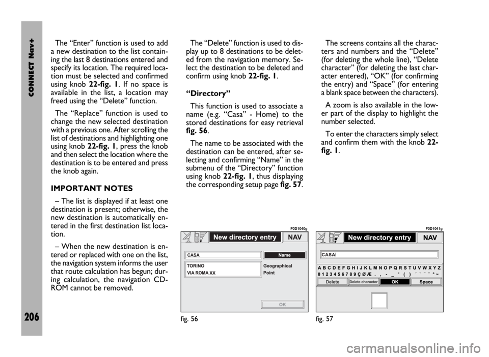
fig. 56.
The name to be associated with the
destination can be entered, after se-
lecting and confirming “Name” in the
submenu of the “Directory” function
using knob 22-fig. 1, thus displaying
the corresponding setup page fig. 57.The screens contains all the charac-
ters and numbers and the “Delete”
(for deleting the whole line), “Delete
character” (for deleting the last char-
acter entered), “OK” (for confirming
the entry) and “Space” (for entering
a blank space between the characters).
A zoom is also available in the low-
er part of the display to highlight the
number selected.
To enter the characters simply select
and confirm them with the knob 22-
fig. 1.
fig. 56
F0D1040g
fig. 57
F0D1041g
Page 208 of 246
CONNECT Nav+
207
Enter the name and confirm with
“OK”. The system informs the user if
the name is already present, with the
possibility to change it: if the user
chooses to change it, a window with
the name to be corrected is displayed,
otherwise, the system returns to the
main navigation function page and
stores also the new destination with
the name already present in the list.
“Map”
When selecting this menu function
to enter the destination, a map section
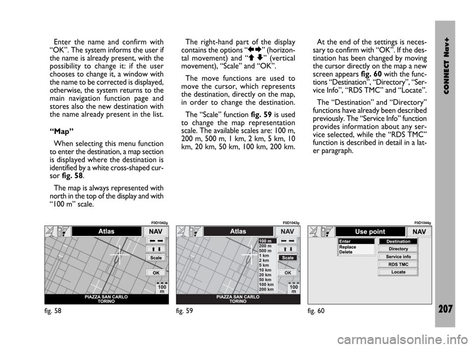
is displayed where the destination is
identified by a white cross-shaped cur-
sor fig. 58.
The map is always represented with
north in the top of the display and with
“100 m” scale. The right-hand part of the display
contains the options “RE” (horizon-
tal movement) and “QZ” (vertical
movement), “Scale” and “OK”.
The move functions are used to
move the cursor, which represents
the destination, directly on the map,
in order to change the destination.
The “Scale” function fig. 59is used
to change the map representation
scale. The available scales are: 100 m,
200 m, 500 m, 1 km, 2 km, 5 km, 10
km, 20 km, 50 km, 100 km, 200 km.At the end of the settings is neces-
sary to confirm with “OK”. If the des-
tination has been changed by moving
the cursor directly on the map a new
screen appears fig. 60with the func-
tions “Destination”, “Directory”, “Ser-
vice Info”, “RDS TMC” and “Locate”.
The “Destination” and “Directory”
functions have already been described
previously. The “Service Info” function
provides information about any ser-
vice selected, while the “RDS TMC”
function is described in detail in a lat-
er paragraph.
fig. 58
F0D1042g
fig. 59
F0D1043g
fig. 60
F0D1044g