lock FIAT DUCATO 244 2005 3.G User Guide
[x] Cancel search | Manufacturer: FIAT, Model Year: 2005, Model line: DUCATO 244, Model: FIAT DUCATO 244 2005 3.GPages: 258, PDF Size: 4.05 MB
Page 30 of 258
29GETTING TO KNOW YOUR VEHICLE
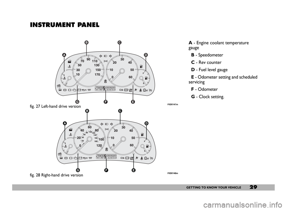
INSTRUMENT PANEL
A- Engine coolant temperature
gauge
B- Speedometer
C- Rev counter
D- Fuel level gauge
E- Odometer setting and scheduled
servicing
F- Odometer
G- Clock setting.
fig. 27 Left-hand drive versionF0D0147m
fig. 28 Right-hand drive versionF0D0148m
Page 31 of 258
30GETTING TO KNOW YOUR VEHICLE
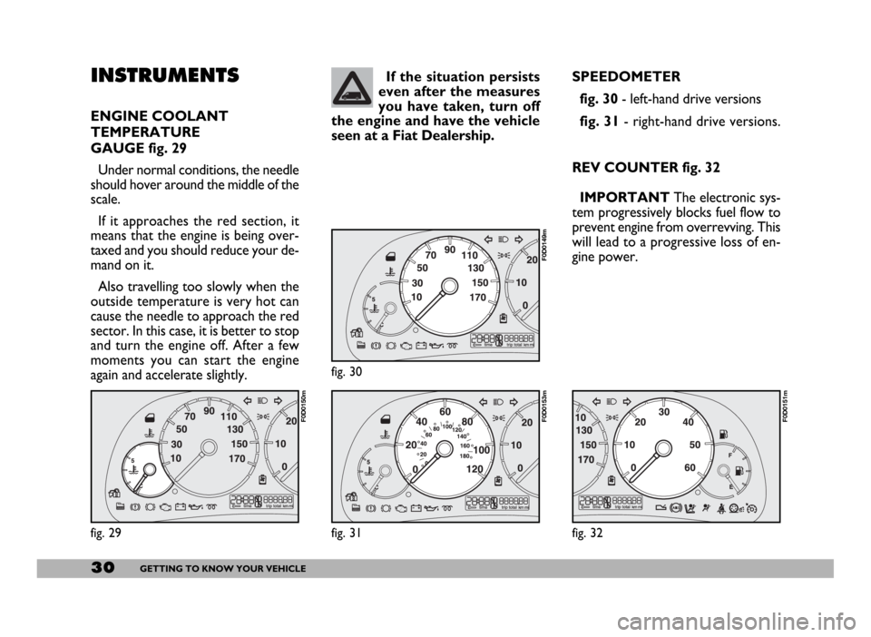
INSTRUMENTS
ENGINE COOLANT
TEMPERATURE
GAUGE fig. 29
Under normal conditions, the needle
should hover around the middle of the
scale.
If it approaches the red section, it
means that the engine is being over-
taxed and you should reduce your de-
mand on it.
Also travelling too slowly when the
outside temperature is very hot can
cause the needle to approach the red
sector. In this case, it is better to stop
and turn the engine off. After a few
moments you can start the engine
again and accelerate slightly.SPEEDOMETER
fig. 30- left-hand drive versions
fig. 31- right-hand drive versions.
REV COUNTER fig. 32
IMPORTANT The electronic sys-
tem progressively blocks fuel flow to
prevent engine from overrevving. This
will lead to a progressive loss of en-
gine power. If the situation persists
even after the measures
you have taken, turn off
the engine and have the vehicle
seen at a Fiat Dealership.
fig. 29
F0D0150m
fig. 30
F0D0149m
fig. 31
F0D0153m
fig. 32
F0D0151m
Page 33 of 258
32GETTING TO KNOW YOUR VEHICLE
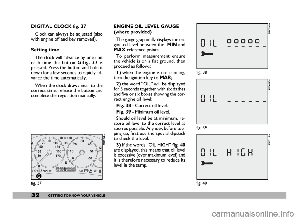
fig. 39
F0D0217m
ENGINE OIL LEVEL GAUGE
(where provided)
The gauge graphically displays the en-
gine oil level between the MINand
MAXreference points.
To perform measurement ensure
the vehicle is on a flat ground, then
proceed as follows:
1)when the engine is not running,
turn the ignition key to MAR;
2)the word “OIL” will be displayed
for 5 seconds together with six dashes
and five or six boxes showing the cor-
rect engine oil level;
Fig. 38- Correct oil level.
Fig. 39- Minimum oil level.
Should oil level be at minimum, re-
store oil level to the correct level as
soon as possible. Anyhow, before top-
ping up, first use the special dipstick
to check the level.
3)If the words “OIL HIGH”fig. 40
are displayed, this means that oil level
is excessive (over maximum level) and
it is therefore necessary to reduce its
level in the sump. DIGITAL CLOCK fig. 37
Clock can always be adjusted (also
with engine off and key removed).
Setting time
The clock will advance by one unit
each time the button G-fig. 37is
pressed. Press the button and hold it
down for a few seconds to rapidly ad-
vance the time automatically.
When the clock draws near to the
correct time, release the button and
complete the regulation manually.
fig. 37
F0D0154m
fig. 38
F0D0254m
fig. 40
F0D0215m
Page 35 of 258
34GETTING TO KNOW YOUR VEHICLE
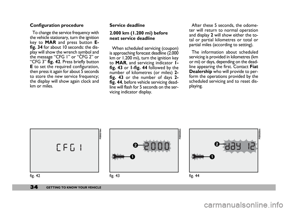
Service deadline
2.000 km (1.200 mi) before
next service deadline
When scheduled servicing (coupon)
is approaching forecast deadline (2.000
km or 1.200 mi), turn the ignition key
to MAR, and servicing indicator 1-
fig. 43or 1-fig. 44followed by the
number of kilometres (or miles) 2-
fig. 43or the number of days 2-
fig. 44, before vehicle servicing dead-
line will flash for 5 seconds on the ser-
vicing indicator display.After these 5 seconds, the odome-
ter will return to normal operation
and display 2will show either the to-
tal or partial kilometres or total or
partial miles (according to setting).
The information about scheduled
servicing is provided in kilometres (km
or mi) or days, depending on the dead-
line appearing the first. Contact Fiat
Dealershipwho will provide to per-
form the operations provided by the
scheduled servicing and to reset dis-
playing.
fig. 43
F0D0220m
Configuration procedure
To change the service frequency with
the vehicle stationary, turn the ignition
key to MARand press button E-
fig. 34for about 10 seconds: the dis-
play will show the wrench symbol and
the message “CFG 1” or “CFG 2” or
“CFG 3” fig. 42. Press briefly button
Eto set the required configuration,
then press it again for about 5 seconds
to store the new service frequency;
the display will show again clock and
km or miles.
fig. 42
F0D0219m
fig. 44
F0D0250m
Page 41 of 258
40GETTING TO KNOW YOUR VEHICLE
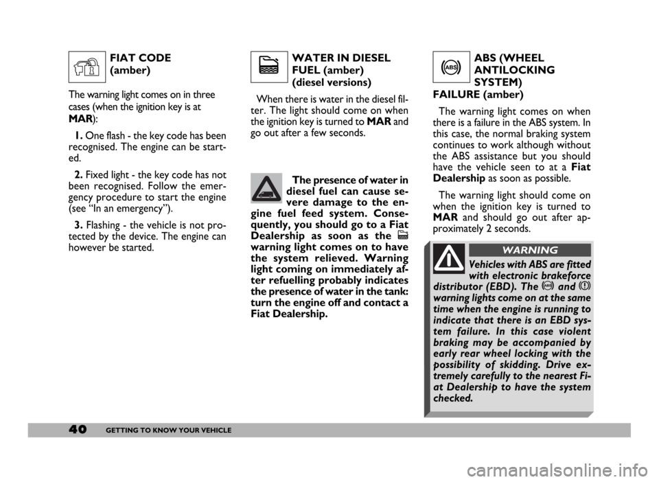
WATER IN DIESEL
FUEL (amber)
(diesel versions)
When there is water in the diesel fil-
ter. The light should come on when
the ignition key is turned to MAR and
go out after a few seconds.ABS (WHEEL
ANTILOCKING
SYSTEM)
FAILURE (amber)
The warning light comes on when
there is a failure in the ABS system. In
this case, the normal braking system
continues to work although without
the ABS assistance but you should
have the vehicle seen to at a Fiat
Dealershipas soon as possible.
The warning light should come on
when the ignition key is turned to
MARand should go out after ap-
proximately 2 seconds.
c
The presence of water in
diesel fuel can cause se-
vere damage to the en-
gine fuel feed system. Conse-
quently, you should go to a Fiat
Dealership as soon as the
c
warning light comes on to have
the system relieved. Warning
light coming on immediately af-
ter refuelling probably indicates
the presence of water in the tank:
turn the engine off and contact a
Fiat Dealership.
>
FIAT CODE
(amber)
The warning light comes on in three
cases (when the ignition key is at
MAR):
1.One flash - the key code has been
recognised. The engine can be start-
ed.
2.Fixed light - the key code has not
been recognised. Follow the emer-
gency procedure to start the engine
(see “In an emergency”).
3. Flashing - the vehicle is not pro-
tected by the device. The engine can
however be started.
Y
Vehicles with ABS are fitted
with electronic brakeforce
distributor (EBD). The >and x
warning lights come on at the same
time when the engine is running to
indicate that there is an EBD sys-
tem failure. In this case violent
braking may be accompanied by
early rear wheel locking with the
possibility of skidding. Drive ex-
tremely carefully to the nearest Fi-
at Dealership to have the system
checked.
WARNING
Page 42 of 258
41GETTING TO KNOW YOUR VEHICLE
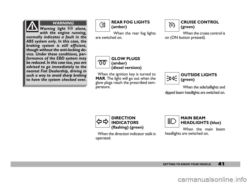
CRUISE CONTROL
(green)
When the cruise control is
on (ON button pressed).
GLOW PLUGS
(amber)
(diesel versions)
When the ignition key is turned to
MAR. The light will go out when the
glow plugs reach the prescribed tem-
perature.
DIRECTION
INDICATORS
(flashing) (green)
When the direction indicator stalk is
operated.OUTSIDE LIGHTS
(green)
When the side/taillights and
dipped beam headlights are switched on.
MAIN BEAM
HEADLIGHTS (blue)
When the main beam
headlights are switched on.
m
y
3
1
REAR FOG LIGHTS
(amber)
When the rear fog lights
are switched on.
4ÜWarning light >alone,
with the engine running,
normally indicates a fault in the
ABS system only. In this case, the
braking system is still efficient,
though without the anti-locking de-
vice. Under these conditions, per-
formance of the EBD system may
be reduced. In this case too, you are
advised to go immediately to the
nearest Fiat Dealership, driving in
such a way to avoid sharp braking
to have the system checked over.
WARNING
Page 43 of 258
42GETTING TO KNOW YOUR VEHICLE
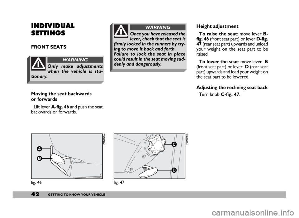
Height adjustment
To raise the seat: move lever B-
fig. 46 (front seat part) or lever D-fig.
47(rear seat part) upwards and unload
your weight on the seat part to be
raised.
To lower the seat: move lever B
(front seat part) or lever D(rear seat
part) upwards and load your weight on
the seat part to be lowered.
Adjusting the reclining seat back
Turn knob C-fig. 47.
fig. 47
F0D0046m
INDIVIDUAL
SETTINGS
FRONT SEATS
Moving the seat backwards
or forwards
Lift lever A-fig. 46and push the seat
backwards or forwards.
fig. 46
F0D0045m
Only make adjustments
when the vehicle is sta-
tionary.
WARNING
Once you have released the
lever, check that the seat is
firmly locked in the runners by try-
ing to move it back and forth.
Failure to lock the seat in place
could result in the seat moving sud-
denly and dangerously.
WARNING
Page 48 of 258
47GETTING TO KNOW YOUR VEHICLE
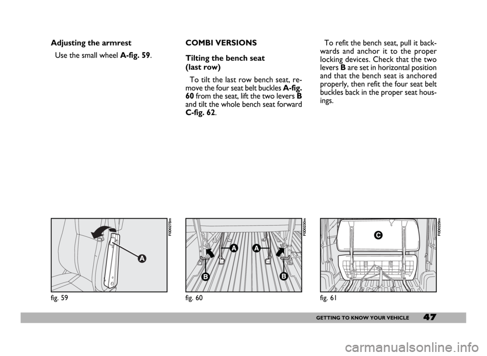
Adjusting the armrest
Use the small wheel A-fig. 59.
fig. 61
F0D0229m
fig. 60
F0D0230m
fig. 59
F0D0278m
COMBI VERSIONS
Tilting the bench seat
(last row)
To tilt the last row bench seat, re-
move the four seat belt buckles A-fig.
60from the seat, lift the two levers B
and tilt the whole bench seat forward
C-fig. 62.To refit the bench seat, pull it back-
wards and anchor it to the proper
locking devices. Check that the two
levers Bare set in horizontal position
and that the bench seat is anchored
properly, then refit the four seat belt
buckles back in the proper seat hous-
ings.
Page 51 of 258
50GETTING TO KNOW YOUR VEHICLE
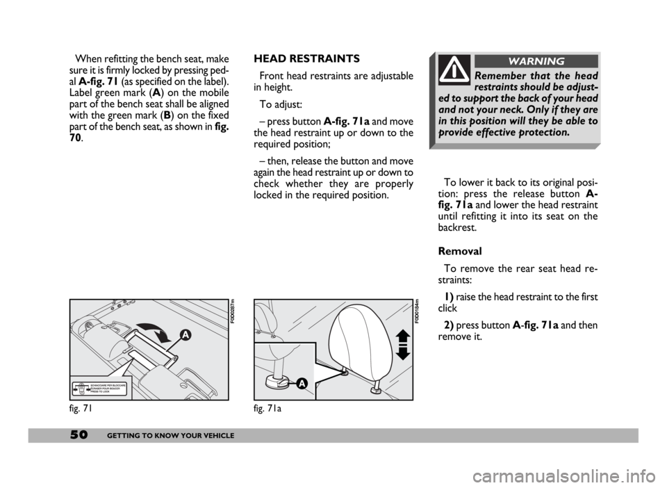
To lower it back to its original posi-
tion: press the release button A-
fig. 71aand lower the head restraint
until refitting it into its seat on the
backrest.
Removal
To remove the rear seat head re-
straints:
1) raise the head restraint to the first
click
2)press button A-fig. 71a and then
remove it.
Remember that the head
restraints should be adjust-
ed to support the back of your head
and not your neck. Only if they are
in this position will they be able to
provide effective protection.
WARNINGHEAD RESTRAINTS
Front head restraints are adjustable
in height.
To adjust:
– press button A-fig. 71aand move
the head restraint up or down to the
required position;
– then, release the button and move
again the head restraint up or down to
check whether they are properly
locked in the required position.
fig. 71
F0D0287m
fig. 71a
F0D0184m
When refitting the bench seat, make
sure it is firmly locked by pressing ped-
al A-fig. 71(as specified on the label).
Label green mark (A) on the mobile
part of the bench seat shall be aligned
with the green mark (B) on the fixed
part of the bench seat, as shown in fig.
70.
Page 52 of 258
51GETTING TO KNOW YOUR VEHICLE
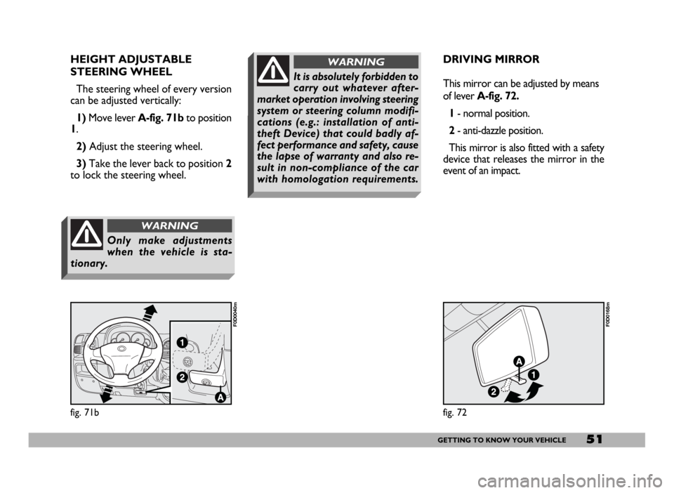
HEIGHT ADJUSTABLE
STEERING WHEEL
The steering wheel of every version
can be adjusted vertically:
1)Move lever A-fig. 71b to position
1.
2)Adjust the steering wheel.
3)Take the lever back to position 2
to lock the steering wheel.
fig. 71b
F0D0040m
Only make adjustments
when the vehicle is sta-
tionary.
WARNING
DRIVING MIRROR
This mirror can be adjusted by means
of lever A-fig. 72.
1- normal position.
2- anti-dazzle position.
This mirror is also fitted with a safety
device that releases the mirror in the
event of an impact.
fig. 72
F0D0168m
It is absolutely forbidden to
carry out whatever after-
market operation involving steering
system or steering column modifi-
cations (e.g.: installation of anti-
theft Device) that could badly af-
fect performance and safety, cause
the lapse of warranty and also re-
sult in non-compliance of the car
with homologation requirements.
WARNING