Diagram FIAT DUCATO 244 2005 3.G Owners Manual
[x] Cancel search | Manufacturer: FIAT, Model Year: 2005, Model line: DUCATO 244, Model: FIAT DUCATO 244 2005 3.GPages: 258, PDF Size: 4.05 MB
Page 100 of 258
99GETTING TO KNOW YOUR VEHICLE
IMPORTANT The cables are se-
cured to the heater cables bundle with
adhesive tape to cut out noise.
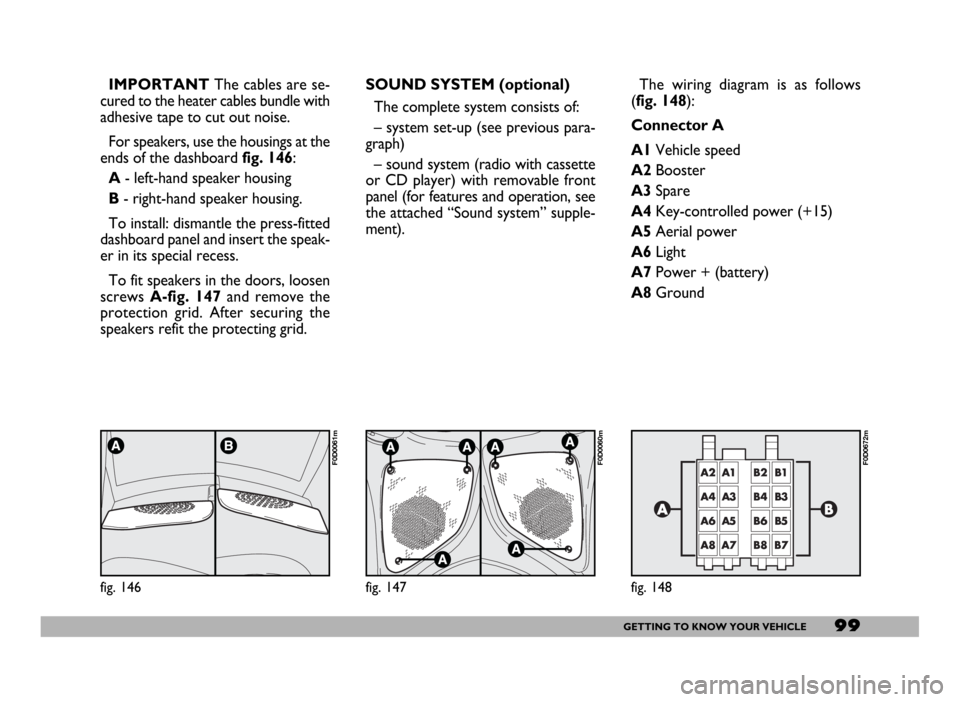
For speakers, use the housings at the
ends of the dashboard fig. 146:
A- left-hand speaker housing
B- right-hand speaker housing.
To install: dismantle the press-fitted
dashboard panel and insert the speak-
er in its special recess.
To fit speakers in the doors, loosen
screws A-fig. 147and remove the
protection grid. After securing the
speakers refit the protecting grid.
fig. 146
F0D0061m
SOUND SYSTEM (optional)
The complete system consists of:
– system set-up (see previous para-
graph)
– sound system (radio with cassette
or CD player) with removable front
panel (for features and operation, see
the attached “Sound system” supple-
ment).
fig. 147
F0D0060m
The wiring diagram is as follows
(fig. 148):
Connector A
A1Vehicle speed
A2Booster
A3Spare
A4Key-controlled power (+15)
A5Aerial power
A6Light
A7Power + (battery)
A8Ground
fig. 148
F0D0672m
Page 101 of 258
100GETTING TO KNOW YOUR VEHICLE
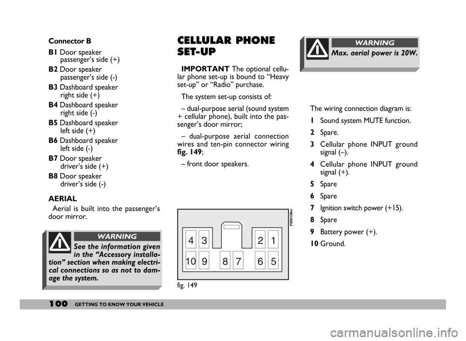
The wiring connection diagram is:
1Sound system MUTE function.
2Spare.
3Cellular phone INPUT ground
signal (–).
4Cellular phone INPUT ground
signal (+).
5Spare
6Spare
7Ignition switch power (+15).
8Spare
9Battery power (+).
10Ground.
Max. aerial power is 20W.
WARNINGConnector B
B1Door speaker
passenger’s side (+)
B2Door speaker
passenger’s side (-)
B3Dashboard speaker
right side (+)
B4Dashboard speaker
right side (-)
B5Dashboard speaker
left side (+)
B6Dashboard speaker
left side (-)
B7Door speaker
driver’s side (+)
B8Door speaker
driver’s side (-)
AERIAL
Aerial is built into the passenger’s
door mirror.CELLULAR PHONE
SET-UP
IMPORTANTThe optional cellu-
lar phone set-up is bound to “Heavy
set-up” or “Radio” purchase.
The system set-up consists of:
– dual-purpose aerial (sound system
+ cellular phone), built into the pas-
senger’s door mirror;
– dual-purpose aerial connection
wires and ten-pin connector wiring
fig. 149;
– front door speakers.
fig. 149
F0D0106m
See the information given
in the “Accessory installa-
tion” section when making electri-
cal connections so as not to dam-
age the system.
WARNING
Page 110 of 258
109GETTING THE BEST OUT OF YOUR VEHICLE
To release the handbrake:
1)slightly lift the handbrake and press
release button A-fig. 1;
2)keep the button pressed and low-
er the lever. Warning light xwill go
out;
3)press the brake pedal when car-
rying out this operation to prevent the
vehicle moving accidentally.
IMPORTANTPull the handbrake
lever only when the vehicle is at a
standstill, or when the vehicle is run-
ning, but however only in case of a fail-
ure of the hydraulic system.
Should the handbrake be exception-
ally used when the vehicle is running, it
is suggested to keep a moderate trac-
tion to avoid causing the rear axle
block, entailing vehicle side skidding.USING THE
MANUAL GEARBOX
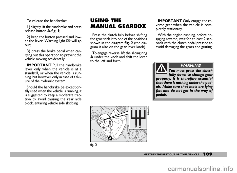
Press the clutch fully before shifting
the gear stick into one of the positions
shown in the diagram fig. 2(the dia-
gram is also on the gear lever knob).
To engage reverse, lift the sliding ring
Aunder the knob and shift the lever
to the left and forth.IMPORTANTOnly engage the re-
verse gear when the vehicle is com-
pletely stationary.
With the engine running, before en-
gaging reverse, wait for at least 2 sec-
onds with the clutch pedal pressed to
avoid damaging the gears and grating.
fig. 2
F0D0057m
You must press the clutch
fully down to change gear
properly. It is therefore essential
that there is nothing under the ped-
als. Make sure that mats are lying
flat and do not get in the way of
pedals.
WARNING
Page 131 of 258
130GETTING THE BEST OUT OF YOUR VEHICLE
The electrical brake or other device
(electrical winch, etc.) must be pow-
ered directly from the battery by
means of a lead with a cross-section
area not smaller than 2.5 mm
2.
In addition to the electrical connec-
tions, only the power wire for an ad-
ditional electrical brake and for inter-
nal trailer lighting with a power not
exceeding 15W can be connected to
the vehicle’s electrical system.
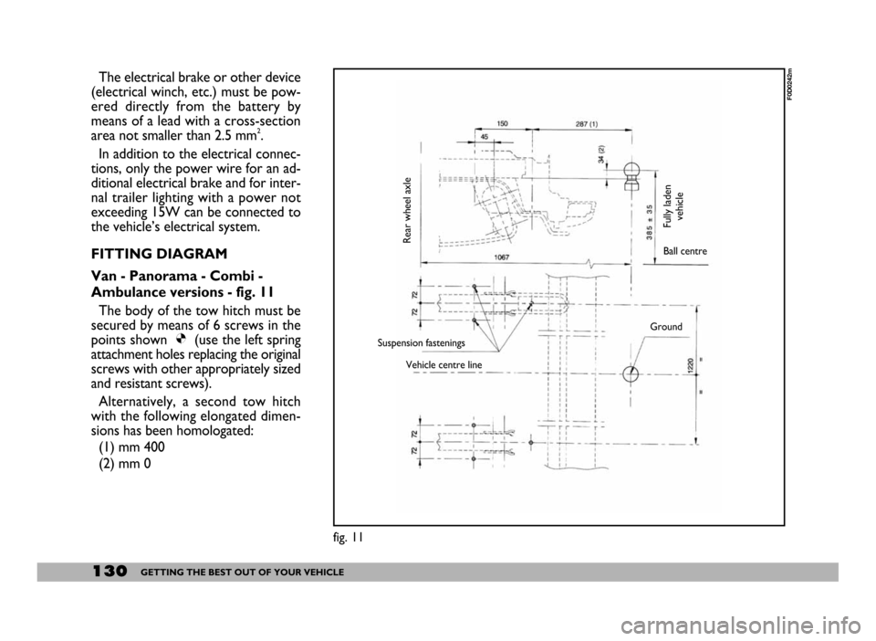
FITTING DIAGRAM
Van - Panorama - Combi -
Ambulance versions - fig. 11
The body of the tow hitch must be
secured by means of 6 screws in the
points shown Ø(use the left spring
attachment holes replacing the original
screws with other appropriately sized
and resistant screws).
Alternatively, a second tow hitch
with the following elongated dimen-
sions has been homologated:
(1) mm 400
(2) mm 0
fig. 11
F0D0242m
Rear wheel axle
Fully laden
vehicleBall centre
Suspension fastenings
Vehicle centre lineGround
Page 251 of 258
250INDEX
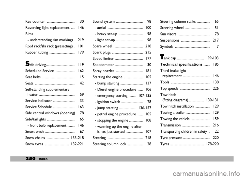
Rev counter ................................. 30
Reversing light replacement ..... 146
Rims
- understanding rim markings .. 219
Roof rack/ski rack (presetting) .. 101
Rubber tubing .............................. 179
Safe driving.................................. 119
Scheduled Service ....................... 162
Seat belts ....................................... 15
Seats ............................................... 42
Self-standing supplementary
heater .......................................... 59
Service indicator .......................... 33
Service Schedule .......................... 163
Side central windows (opening) 78
Side/taillights ................................. 65
- front bulb replacement ......... 146
Smart wash ................................... 67
Snow chains .......................... 133-218
Snow tyres ............................ 132-221Sound system ............................... 98
- aerial ......................................... 100
- heavy set-up ............................ 98
- light set-up ............................... 98
Spare wheel .................................. 218
Spark plugs .................................... 215
Speed limiter ................................ 177
Speedometer ................................ 30
Spray nozzles ............................... 181
Starting the engine ...................... 105
- bump starting .......................... 137
- Diesel engine procedure ...... 106
- emergency starting ......... 107-135
- ignition switch ......................... 28
- jump starting .................... 136-157
- petrol engine procedure ...... 105
- stopping the engine ................ 108
- warming up the engine after
it has just started ................... 107
Steering ......................................... 218
Steering column lock .................. 28Steering column stalks ............... 65
Steering wheel ............................. 51
Sun visors ...................................... 78
Suspensions .................................. 217
Symbols ......................................... 7
Tank cap ................................ 99-103
Technical specifications........ 185
Third brake light
replacement ................................. 146
Tools ................................................ 138
Top speeds ..................................... 226
Tow hitch
(fitting diagrams)................... 130-131
Tow hitch installation .................. 129
Towing a trailer ............................. 129
Towing the vehicle ....................... 159
Transmission .................................. 216
Transporting children in safety .. 22
Tyre pressure ................................. 220
Tyres ......................................... 178-220