ECO mode FIAT DUCATO 244 2005 3.G Owners Manual
[x] Cancel search | Manufacturer: FIAT, Model Year: 2005, Model line: DUCATO 244, Model: FIAT DUCATO 244 2005 3.GPages: 258, PDF Size: 4.05 MB
Page 38 of 258
37GETTING TO KNOW YOUR VEHICLE
EOBD ENGINE
FAILURE CONTROL
SYSTEM
(petrol versions only) (amber)
In normal conditions, the warning
light will come on when the ignition
key is turned to MARand should go
out as soon as the engine is started.
The initial lighting up shows that the
warning light is working properly.
If the warning light either stays on or
comes on while travelling:
1. Fixed light- warning of a fuel
feed/ignition system failure which may
increase emissions in exhaust or cause
possible drops in performance, poor
handling and high consumption.
In such conditions, you can contin-
ue driving but you should not tax the
engine and you should moderate the
speed. Prolonged use with the warn-
ing light on can cause damage. Contact
a Fiat Dealershipas soon as possi-
ble. The warning light will go out when
the failure disappears. In any case, the
system will store the error.
2. Flashing- warning that the cata-
lyst can be damaged (see “EOBD sys-
tem” in this chapter).
If the warning light starts flashing, re-
lease the accelerator pedal and slow
the engine until the warning light stops
flashing. Continue driving at moderate
speed, preventing the warning light
from coming on again. Contact a Fi-
at Dealership as soon as possible.INJECTION SYSTEM
FAILURE
(diesel versions) (red)
When there is a fault in the injection
system.
The warning light should come on
when the ignition key is turned to
MARand go out after a few seconds.
The warning light will stay on or come
on when travelling to indicate imperfect
operation of the injection system with
possible loss of performance, poor han-
dling and higher consumption.
In these conditions, you can contin-
ue driving but you should avoid de-
manding efforts from the engine or
high speeds. Contact a Fiat Dealer-
shipas soon as possible.
Prolonged use of the vehicle with the
warning light on can cause damage to
the engine, especially in the event of
misfiring. The vehicle can only be dri-
ven for a short period of time at low
speeds.
Occasional and brief lighting of the
warning light is meaningless.
UU
Contact a Fiat Dealer-
ship as soon as possible if
the
Uwarning light ei-
ther does not come on when the
key is turned to MAR or comes
on, with fixed light or flashing
light, when travelling. Warning
light
Uoperation can be checked
by means of special equipment by
traffic agents. Always comply
with the road traffic regulations
in force in the Country where you
are travelling.
Page 64 of 258
63GETTING TO KNOW YOUR VEHICLE
IMPORTANTTo recall other pre-
set times, press button 6within 10
seconds.
– press button 5or 7to select the
starting time required within 10 sec-
onds.
IMPORTANTStarting time disap-
pears and the number 3(correspond-
ing to the selected preset time) ap-
pears on the display to confirm the
starting time has been entered.
Deleting a programmed
starting time fig. 89
To delete the programmed starting
time, press button 6briefly: the dis-
play light will go off and number 3cor-
responding to the selected preset
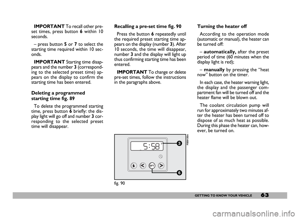
time will disappear.Recalling a pre-set time fig. 90
Press the button 6repeatedly until
the required preset starting time ap-
pears on the display (number 3). After
10 seconds, the time will disappear,
number 3and the display will light up
thus confirming starting time has been
entered.
IMPORTANTTo change or delete
pre-set times, follow the instructions
in the paragraphs above.Turning the heater off
According to the operation mode
(automatic or manual), the heater can
be turned off:
–automatically,after the preset
period of time (60 minutes when the
display light is red);
– manuallyby pressing the “heat
now” button on the timer.
In each case, the heater warning light,
the display and the passenger com-
partment fan will be turned off and the
heater flame will be blown out.
The coolant circulation pump will
run for approximately two minutes af-
ter the heater has been turned off to
dispose of as much heat as possible.
During this phase the heater can, how-
ever, be turned on.
fig. 90
F0D0135m
Page 71 of 258
70GETTING TO KNOW YOUR VEHICLE
To increase the memorised
speed
The speed memorised can be in-
creased in two ways:
1 -pressing the accelerator and then
memorising the new speed reached
(pressing button + for more than
three seconds);
2 -pressing briefly button +: each
pressing will correspond to a slight in-
crease in speed (about 2.5 km/h) while
pressing continuously will correspond
to a continuous speed increase. Re-
leasing the button the new speed will
be memorised automatically.
To reduce the memorised
speed
The speed memorised can be re-
duced in two ways:
1 -disengaging the device (for in-
stance pressing the brake pedal) and
then memorising the new speed
(pressing button +for more than
three seconds);
2 -pressing button –until reaching
the new speed which will be memo-
rised automatically.To set to zero the memorised
speed
The memorised speed is automati-
cally reset:
– turning the engine off;
– pressing buttonOFF.Do not engage the device in town or
in busy flowing traffic conditions.
When travelling with the
cruise control on, do not
move the gearshift lever to neutral
and to not move the automatic
gearbox selector to N. We suggest
to engage the cruise control only
when the traffic and road condi-
tions allow doing it in complete
safety and so: straight and dry
roads, freeways or motorways,
smooth flowing traffic and even as-
phalt.
WARNING
The cruise control can be en-
gaged only with speeds high-
er than 40 km/h. The device may on-
ly be engaged in 4
thor 5thgear, de-
pending on the speed of the vehicle.
On vehicles with electronic automat-
ic gearbox it can only be engaged
with selector to D, in automatic mode
without then moving the selector
manually, or with 3
rdor 4thgear in se-
quential operation. Travelling down-
hill with the device engaged, the ve-
hicle speed may increase more than
the memorised one, due to the
change in the engine load.
WARNING
Page 76 of 258
75GETTING TO KNOW YOUR VEHICLE
When tilted, the box cover becomes
a writing/reading desk with a clip to
hold sheets/papers, similar to that
shown in fig. 112.
Refrigerator version (food box)
In the refrigerator version, the box
has an internal space of about 12 litres
capacity that can contain 2 one and a
half litre bottles. In this version the
box is insulated and it is fitted with an
electric device to warm up or cool the
box interior as required.
This box can be used as food con-
tainer. Food shall be suitably packed
to avoid direct contact with the inner
walls of the box.
When used for cooling, a tempera-
ture difference of approx. 18 °C can
be achieved between the temperature
inside the box and that of the passen-
ger compartment after a certain time
of operation (with insulated cover and
plug closed). The lowest possible tem-
perature that can be reached in any
case is not lower than 8 -10 °C.To prevent the risk of running the bat-
tery down, the system is connected via
the ignition key; as a result the box will
only work when the engine is running.
You should remove perishables from
the box if you leave the vehicle parked
for longer than two hours.
For proper operation it is necessary
that ventilation grids (outside the box
and on one of the inside walls) should
not be clogged.
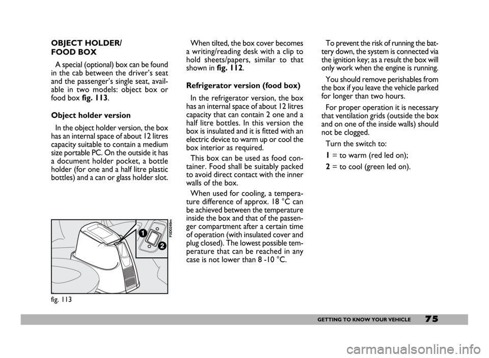
Turn the switch to:
1= to warm (red led on);
2= to cool (green led on).
fig. 113
F0D0249m
OBJECT HOLDER/
FOOD BOX
A special (optional) box can be found
in the cab between the driver’s seat
and the passenger’s single seat, avail-
able in two models: object box or
food box fig. 113.
Object holder version
In the object holder version, the box
has an internal space of about 12 litres
capacity suitable to contain a medium
size portable PC. On the outside it has
a document holder pocket, a bottle
holder (for one and a half litre plastic
bottles) and a can or glass holder slot.
Page 115 of 258
114GETTING THE BEST OUT OF YOUR VEHICLE
SEQUENTIAL MANUAL
OPERATION
For the sequential manual operation
mode, move the lever to the left sec-
tor B-fig. 4with two positions:
(+) = engagement of the higher ra-
tio;
(–) = engagement of the lower ratio.
Moving the gearshift lever to the
manual sector is only possible from
position D: the ratio selected by the
automatic gearbox when the lever is
moved will remain engaged.
When the sequential manual mode is
selected, the display shows the en-
gaged gear fig. 6.
To select the higher ratio move the
lever in the (+) direction and to shift
down move the lever to (–).IMPORTANTIf the request to
downshift would cause engine
overevving, this is eliminated by the
electronic control unit. Moreover, if
the manually engaged gear causes en-
gine overevving, the electronic control
unit will shift gear automatically to the
most appropriate one (AUTO-UP).
When the sequential man-
ual mode has been set and
a high gear is engaged, to acceler-
ate rapidly, for example to over-
take, it is necessary to downshift
by hand: the kickdown feature
cannot be engaged!
WARNING
Engaging the automatic
WINTER programme
(only with lever in “D”)
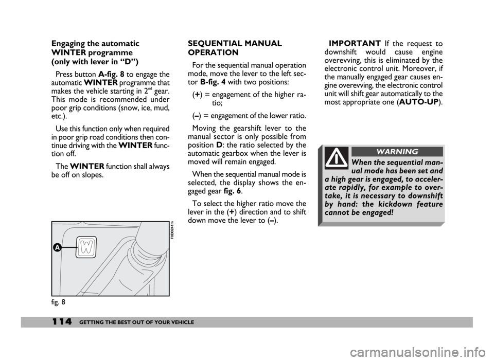
Press button A-fig. 8to engage the
automatic WINTERprogramme that
makes the vehicle starting in 2
ndgear.
This mode is recommended under
poor grip conditions (snow, ice, mud,
etc.).
Use this function only when required
in poor grip road conditions then con-
tinue driving with the WINTERfunc-
tion off.
The WINTERfunction shall always
be off on slopes.
fig. 8
F0D0241m
Page 116 of 258
115GETTING THE BEST OUT OF YOUR VEHICLE
Moving the lever back to position D
the gearbox instantly resumes the au-
tomatic mode selecting the ratio ac-
cording to the driving characteristics.
IMPORTANTThe electronic con-
trol unit is programmed to change
gear one at a time, therefore repeat-
ed fast actuations will not result in re-
peated engagements of the gears. The
higher or lower gear is engaged mov-
ing the lever to the (+) or (–) position
when the previous request has been
performed.
In the event of a fault to the sequen-
tial manual system, the system will se-
lect the automatic mode.FAILURE INDICATIONS
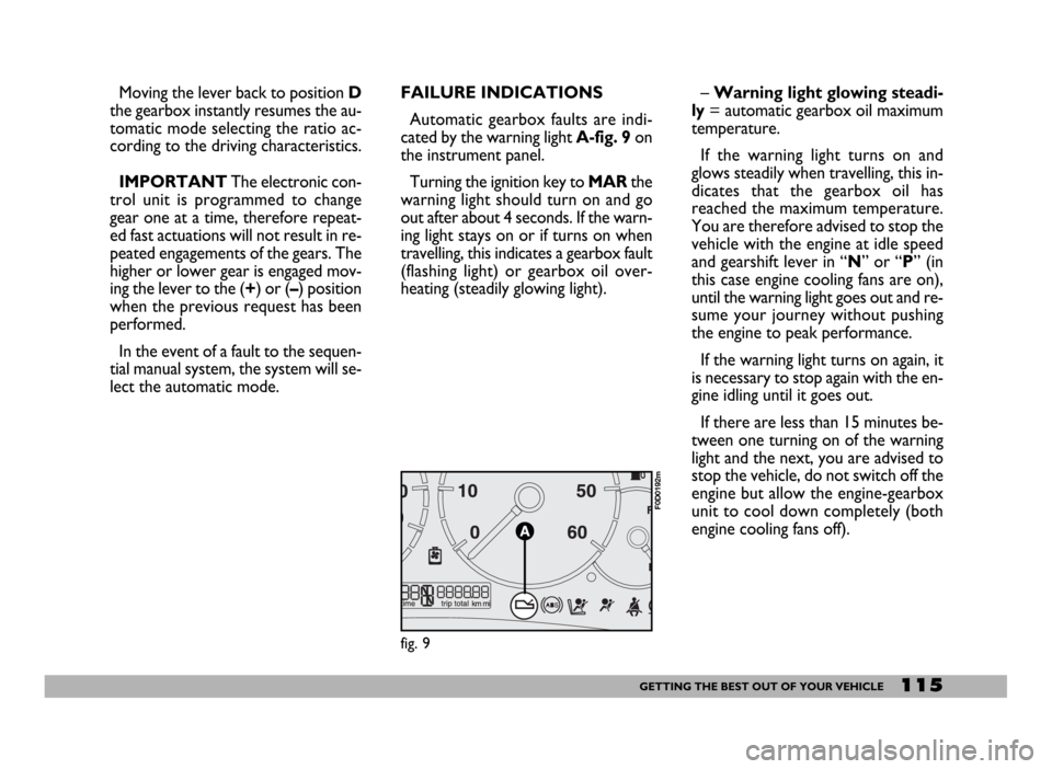
Automatic gearbox faults are indi-
cated by the warning light A-fig. 9 on
the instrument panel.
Turning the ignition key to MARthe
warning light should turn on and go
out after about 4 seconds. If the warn-
ing light stays on or if turns on when
travelling, this indicates a gearbox fault
(flashing light) or gearbox oil over-
heating (steadily glowing light).– Warning light glowing steadi-
ly= automatic gearbox oil maximum
temperature.
If the warning light turns on and
glows steadily when travelling, this in-
dicates that the gearbox oil has
reached the maximum temperature.
You are therefore advised to stop the
vehicle with the engine at idle speed
and gearshift lever in “N” or “P” (in
this case engine cooling fans are on),
until the warning light goes out and re-
sume your journey without pushing
the engine to peak performance.
If the warning light turns on again, it
is necessary to stop again with the en-
gine idling until it goes out.
If there are less than 15 minutes be-
tween one turning on of the warning
light and the next, you are advised to
stop the vehicle, do not switch off the
engine but allow the engine-gearbox
unit to cool down completely (both
engine cooling fans off).
fig. 9
F0D0192m
Page 217 of 258
216TECHNICAL SPECIFICATIONS
BRAKES
SERVICE AND EMERGENCY
BRAKES
Front: disc, floating caliper with two
operating cylinders for each wheel and
pad wear warning light.
Rear: self-centring shoes and micro-
metric mechanism for clearance take-
up.
Certain versions are fitted with rear
disc brakes with Drum in hat device
(i.e. drum on disc to block the vehicle
when parked with handbrake en-
gaged).
Cross-over hydraulic circuit control.
Four sensors ABS system with EBD.
Automatic recovery of the friction
gasket wear; versions with rear disc
brake excluded (Drum in hat ver-
sions).
Lacking ABS system brakeforce dis-
tributor acting on rear brake hydraulic
circuit according to rear axle load.HANDBRAKE
Controlled by a lever, it works me-
chanically on the rear brake shoes.
For versions with rear disc brakes,
the handbrake works on the Drum in
hat device shoes.
IMPORTANTPull the handbrake
lever only when the vehicle is at a
standstill, or when the vehicle is run-
ning, but however only in case of a
failure of the hydraulic system.
Should the handbrake be exception-
ally used when the vehicle is running,
it is suggested to keep a moderate
traction to avoid causing the rear axle
block, entailing vehicle side skidding.
TRANSMISSION
CLUTCH
Hydraulically controlled without
travel-free pedal.
MECHANICAL GEARBOX
AND DIFFERENTIAL
Five forward gears and reverse with
synchromesh for front gear engage-
ment.
Cyclical gear reduction and differen-
tial assembly incorporated in the gear-
box.
Drive transmission to the front
wheels by means of drive shafts con-
nected to the differential assembly and
the wheels with CV joints.
Water, ice or salt on road
surfaces can deposit on
brake discs, reducing braking effi-
ciency on the first braking.
WARNING
Page 250 of 258

249INDEX
Glove compartment/oddment
compartment ............................. 73
Headlight washer ...................... 181
Headlights
- beam adjustment .................... 86
Head restraints ............................ 50
Heat flange .................................... 106
Heating .......................................... 56
Heating and ventilation .............. 54
Identification data ...................... 185
If a bulb burns out ...................... 141
If an accident occurs .................. 160
If anyone is injured
(during accidents) ..................... 161
If an exterior light burns out ... 143
If an interior light burns out .... 148
Ignition switch ............................. 28
In an emergency..................... 135
Individual settings ........................ 42
Instrument panel ......................... 29Instruments .................................. 30
Interior equipment ..................... 73
Interiors ........................................ 184
Jacking the vehicle .................... 158
Jump starting ........................... 136-157
Keys ............................................ 7
Load recommendations .......... 126
Main beam headlights ............ 65
- bulb replacement ................... 143
Manual gearbox ........................... 109
Mobile foot board ....................... 80
Model plate ................................... 185
Multimeter .................................... 78
Number plate light
replacement ............................... 147
Object holder/
food box ..................................... 75
Oddment compartments............ 73
Odometer ...................................... 31
Paintwork .................................... 182
Parking ............................................ 108
Parking sensors ............................. 67
Performance .................................. 226
Pollen filter .................................... 173
Power steering fluid level ........... 171
Pretensioners ................................ 18
Protecting the environment ...... 104
Radio transmitters
and cellular phones .................. 101
Reading/writing desk .................. 74
Rear fog light replacement ....... 145
Rearview camera ........................ 67
Rearview mirrors ................ 51-52
Recharging the battery .............. 157
Remote control ........................... 9