set clock FIAT DUCATO 244 2005 3.G Owners Manual
[x] Cancel search | Manufacturer: FIAT, Model Year: 2005, Model line: DUCATO 244, Model: FIAT DUCATO 244 2005 3.GPages: 258, PDF Size: 4.05 MB
Page 15 of 258
14GETTING TO KNOW YOUR VEHICLE
Do not leave the key inserted in the
switch. Cover the keyhole with the
rubber cap to prevent dust and wa-
ter getting in.
Emergency keys should be left in the
car coupled with the switch.
HOW TO KNOW IF THE
ALARM HAS GONE OFF
After deactivating the system, led A-
fig. 9will indicate the theft attempt
specifying also the cause of the alarm:
fixed light:remote control bat-
tery down
1 blink:right-hand door
2 blinks:left-hand door
5 blinks:volumetric sensors
(indicate a movement
inside the passenger’s
compartment)
6 blinks:bonnet To cut off the alarm before this,
press the remote control button; if
this is unsuccessful, turn the emer-
gency key to OFF(see next paragraph
“How to turn the alarm off”)
HOW TO TURN
THE ALARM OFF
If the remote control batteries run
down, or the car alarm system is
faulty, the electronic alarm can be cut
out by using one of the two emer-
gency keys supplied set on the system
deactivation control unit (that is
housed in the fuse box on the right
side of the dashboard).
To do this, open the fuse box, take
off the switch rubber cap, insert the
key and turn it counterclockwise
(OFFposition); the system is now de-
activated.
To turn the system back on, turn the
key clockwise (ONposition).7 blinks:load
compartment
8 blinks:tampering with
ignition switch
9 blinks:alarm wires cut
10 blinks:at least three causes
of alarm.
The led goes off when turning the
key to MAR or after about 2 minutes
blinking.
Since the electronic car
alarm absorbs electricity,
if you will not be using
your car for more than a month,
switch the system off with the re-
mote control and turn the emer-
gency key to OFF.
Page 30 of 258
29GETTING TO KNOW YOUR VEHICLE
INSTRUMENT PANEL
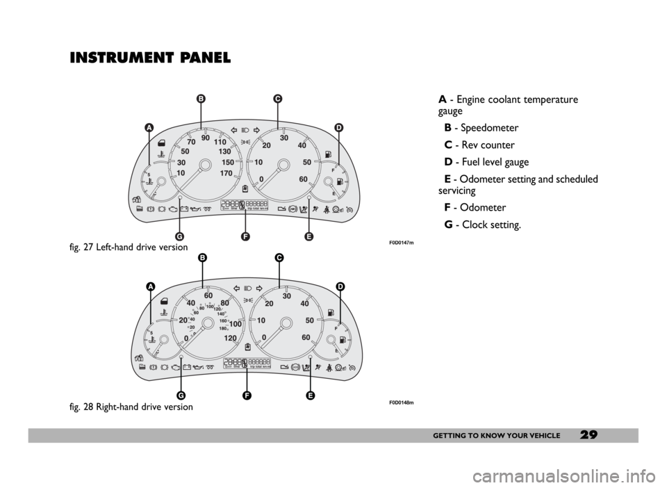
A- Engine coolant temperature
gauge
B- Speedometer
C- Rev counter
D- Fuel level gauge
E- Odometer setting and scheduled
servicing
F- Odometer
G- Clock setting.
fig. 27 Left-hand drive versionF0D0147m
fig. 28 Right-hand drive versionF0D0148m
Page 33 of 258
32GETTING TO KNOW YOUR VEHICLE
fig. 39
F0D0217m
ENGINE OIL LEVEL GAUGE
(where provided)
The gauge graphically displays the en-
gine oil level between the MINand
MAXreference points.
To perform measurement ensure
the vehicle is on a flat ground, then
proceed as follows:
1)when the engine is not running,
turn the ignition key to MAR;
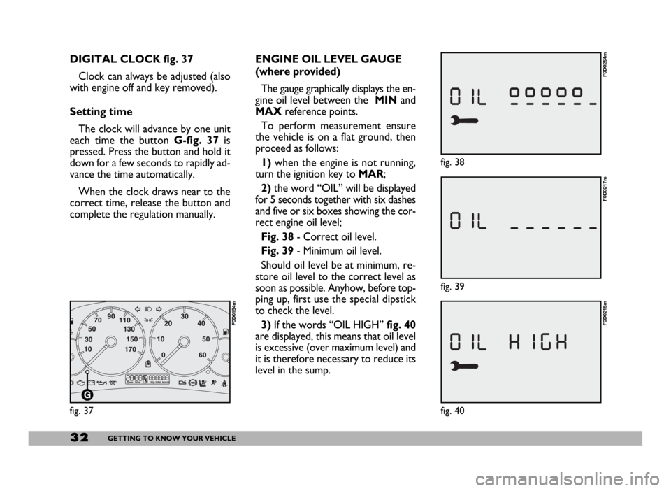
2)the word “OIL” will be displayed
for 5 seconds together with six dashes
and five or six boxes showing the cor-
rect engine oil level;
Fig. 38- Correct oil level.
Fig. 39- Minimum oil level.
Should oil level be at minimum, re-
store oil level to the correct level as
soon as possible. Anyhow, before top-
ping up, first use the special dipstick
to check the level.
3)If the words “OIL HIGH”fig. 40
are displayed, this means that oil level
is excessive (over maximum level) and
it is therefore necessary to reduce its
level in the sump. DIGITAL CLOCK fig. 37
Clock can always be adjusted (also
with engine off and key removed).
Setting time
The clock will advance by one unit
each time the button G-fig. 37is
pressed. Press the button and hold it
down for a few seconds to rapidly ad-
vance the time automatically.
When the clock draws near to the
correct time, release the button and
complete the regulation manually.
fig. 37
F0D0154m
fig. 38
F0D0254m
fig. 40
F0D0215m
Page 35 of 258
34GETTING TO KNOW YOUR VEHICLE
Service deadline
2.000 km (1.200 mi) before
next service deadline
When scheduled servicing (coupon)
is approaching forecast deadline (2.000
km or 1.200 mi), turn the ignition key
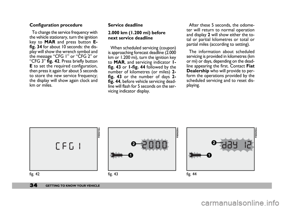
to MAR, and servicing indicator 1-
fig. 43or 1-fig. 44followed by the
number of kilometres (or miles) 2-
fig. 43or the number of days 2-
fig. 44, before vehicle servicing dead-
line will flash for 5 seconds on the ser-
vicing indicator display.After these 5 seconds, the odome-
ter will return to normal operation
and display 2will show either the to-
tal or partial kilometres or total or
partial miles (according to setting).
The information about scheduled
servicing is provided in kilometres (km
or mi) or days, depending on the dead-
line appearing the first. Contact Fiat
Dealershipwho will provide to per-
form the operations provided by the
scheduled servicing and to reset dis-
playing.
fig. 43
F0D0220m
Configuration procedure
To change the service frequency with
the vehicle stationary, turn the ignition
key to MARand press button E-
fig. 34for about 10 seconds: the dis-
play will show the wrench symbol and
the message “CFG 1” or “CFG 2” or
“CFG 3” fig. 42. Press briefly button
Eto set the required configuration,
then press it again for about 5 seconds
to store the new service frequency;
the display will show again clock and
km or miles.
fig. 42
F0D0219m
fig. 44
F0D0250m
Page 62 of 258
61GETTING TO KNOW YOUR VEHICLE
IMPORTANTThe heater is
equipped with a thermal switch which
cuts off the heater in the event of
overheating caused by low or leaking
coolant. In this case, press the pro-
gram selection button to start the
heater again after repairing the cool-
ing system fault and/or topping up the
fluid.
The heater can turn itself off after en-
gine ignition or if the flame goes out.
In this case, turn the heater off man-
ually and attempt to turn it back on
again. If you cannot turn the heater on,
contact a Fiat Dealership.Turning the heater on
Before turning the heater on check
that:
– the heating/ventilation unit knob is
turned to “warm air”;
– the heating/ventilation fan speed
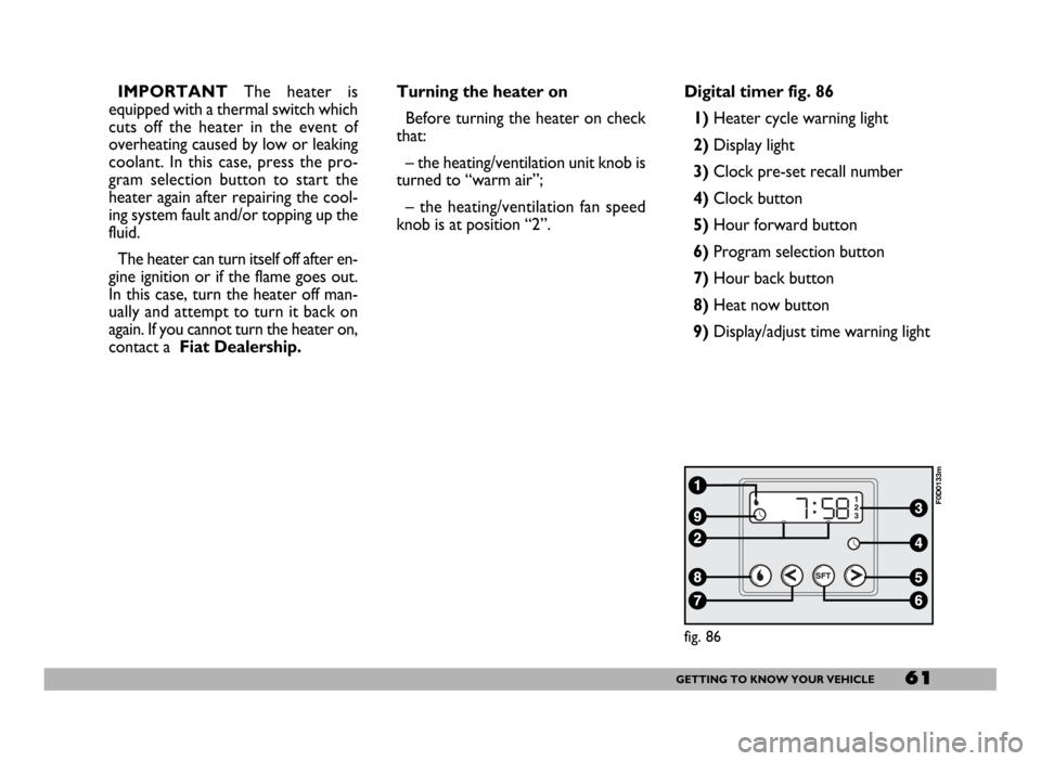
knob is at position “2”.Digital timer fig. 86
1) Heater cycle warning light
2)Display light
3)Clock pre-set recall number
4)Clock button
5)Hour forward button
6)Program selection button
7)Hour back button
8) Heat now button
9) Display/adjust time warning light
fig. 86
F0D0133m
Page 63 of 258
62GETTING TO KNOW YOUR VEHICLE
fig. 87
F0D0132m
fig. 88
F0D0134m
fig. 89
F0D0136m
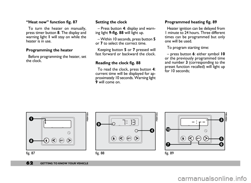
“Heat now” function fig. 87
To turn the heater on manually,
press timer button 8. The display and
warning light 1will stay on while the
heater is in use.
Programming the heater
Before programming the heater, set
the clock.Setting the clock
– Press button 4: display and warn-
ing light 9-fig. 88will light up.
– Within 10 seconds, press button 5
or 7to select the correct time.
Keeping button 5or 7pressed will
fast forward or backward the clock.
Reading the clock fig. 88
To read the clock, press button 4:
current time will be displayed for ap-
proximately 10 seconds. Warning light
9will come on.Programmed heating fig. 89
Heater ignition can be delayed from
1 minute to 24 hours. Three different
times can be programmed but only
one will be used.
To program starting time:
– press button 6: either symbol 10
or the previously programmed time
and number 3 (corresponding to the
preset function recalled) will light up
for 10 seconds;
Page 147 of 258
146IN AN EMERGENCY
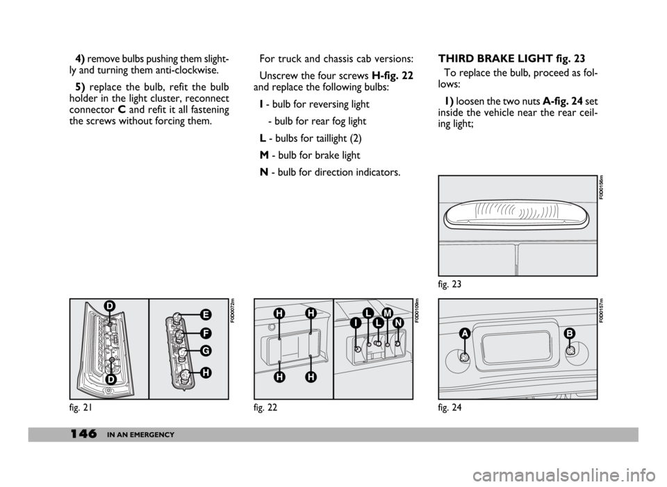
THIRD BRAKE LIGHT fig. 23
To replace the bulb, proceed as fol-
lows:
1)loosen the two nuts A-fig. 24set
inside the vehicle near the rear ceil-
ing light; 4)remove bulbs pushing them slight-
ly and turning them anti-clockwise.
5) replace the bulb, refit the bulb
holder in the light cluster, reconnect
connector Cand refit it all fastening
the screws without forcing them.For truck and chassis cab versions:
Unscrew the four screws H-fig. 22
and replace the following bulbs:
I- bulb for reversing light
- bulb for rear fog light
L- bulbs for taillight (2)
M- bulb for brake light
N- bulb for direction indicators.
fig. 21
F0D0072m
fig. 22
F0D0109m
fig. 23
F0D0156m
fig. 24
F0D0157m