climate control FIAT DUCATO BASE CAMPER 2014 Owner handbook (in English)
[x] Cancel search | Manufacturer: FIAT, Model Year: 2014, Model line: DUCATO BASE CAMPER, Model: FIAT DUCATO BASE CAMPER 2014Pages: 367, PDF Size: 20.39 MB
Page 42 of 367
IMPORTANT The rapid demisting/
defrosting function for the windows
remains on for about 3 minutes from
when the engine coolant reaches the
appropriate temperature for a rapid
demisting of the windows.
When this function is active, the LED on
the corresponding button and the one
on the heated rear window button
switch on. The message FULL AUTO
goes off on the display.
You can only adjust the fan speed and
switch off the heated rear window
manually when this function is active.
To restore the previous operating
conditions, simply press button B, air
recirculation button G, compressor
button F or AUTO button A.
NoteTo guarantee rapid demisting/
defrosting, if an additional heater/air
conditioner is present (under the front
or rear seat on Panorama and Combi
versions), if activated, deactivate it
using button F (LED off) located
in control panel F fig. 55.Switching the system
OFF (E)
Press button E to switch the climate
control system off. The display will go
out.
The following climate control conditions
will be present when the system is off:
❒display off;
❒temperature setting not displayed;
❒air recirculation on, thereby insulating
the passenger compartment from the
outside (recirculation LED on);
❒climate control compressor off;
❒fan off.
Press the AUTO button to switch the
climate control system back on in
full automatic mode.
ADDITIONAL
HEATER(for versions/markets, where provided)
On some versions, an additional heater
is also present beneath the driver's
seat. The fan for this heater is operated
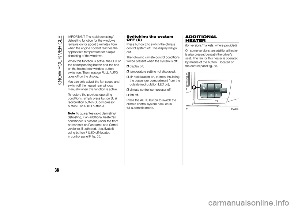
by means of the button F located on
the control panel fig. 53.
MODE
F
53
F1A0305
38
KNOW YOUR VEHICLE
Page 44 of 367

IMPORTANT The heater is equipped
with a thermal limiter that cuts off
combustion in the case of overheating
due to insufficient coolant/coolant
leaks. In this case, after repairing the
fault in the cooling system and/or
topping up the fluid, press the program
selection button before turning the
heater back on.
The heater can turn off spontaneously
due to misfiring after start-up or
because the flame goes out during
operation. In this case, carry out the
turning off procedure and try to turn the
heater back on. If it still does not work,
consult a Fiat Dealership.
Activation of the heating
system
When an automatic climate control
system is present, the control unit sets
the air temperature and distribution
when the heater is turned on from the
park position. When a manual
heater/climate control is present, to
obtain maximum heater efficiency,
check that the passenger compartment
heating/ventilation temperature
adjustment knob is in the 'hot air'
position.
To prioritise passenger compartment
pre-heating, set the air distribution knob
to the
position.To prioritise windscreen demisting, set
the air distribution knob to
position.
To obtain both functions, set the air
distribution knob to
position.
Digital timer fig. 54
1) Time/timer display
2) Ventilation warning light
3) Time "forward" adjustment button
4) Program selection button
5) Clock preselection recall number
6) Activation button for immediate
heating
7) Time adjustment/reading warning
light
8) Time "backward" adjustment button
9) Heater cycle warning lightHeating turned on
immediately
To switch the system on manually,
press the button 6 of the timer: the
display and warning light 9 will light up
and remain on the entire time the
system is working.
Switching on time will disappear after
10 seconds.
Programmed activation
of heating
Before programming system activation,
it is essential to set the time.
Setting the current time
❒Keep button 4 pressed: the display
and warning light 7 will switch on;
❒At the same time, within 10 seconds,
press buttons 3 or 8 to select the
exact time;
❒Release button 4.
When the display goes off, the current
time is stored.
Continuing to press the buttons 3 or 8
will move the digits on the clock
forwards or backwards faster.
Time setting is not possible when the
heating or ventilation functions are
active.
54
F1A0057
40
KNOW YOUR VEHICLE
Page 47 of 367
ADDITIONAL REAR
HEATING (Panorama and
Combi)
(for versions/markets, where provided)
The Panorama and Combi versions
are equipped with a main heating
system plus an additional system
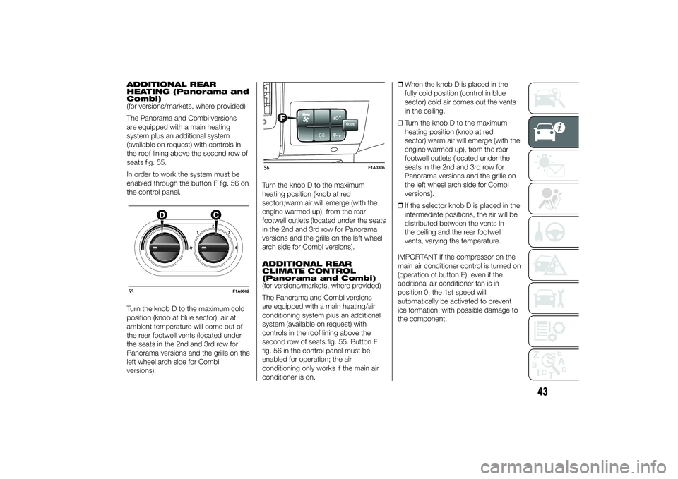
(available on request) with controls in
the roof lining above the second row of
seats fig. 55.
In order to work the system must be
enabled through the button F fig. 56 on
the control panel.
Turn the knob D to the maximum cold
position (knob at blue sector); air at
ambient temperature will come out of
the rear footwell vents (located under
the seats in the 2nd and 3rd row for
Panorama versions and the grille on the
left wheel arch side for Combi
versions);Turn the knob D to the maximum
heating position (knob at red
sector);warm air will emerge (with the
engine warmed up), from the rear
footwell outlets (located under the seats
in the 2nd and 3rd row for Panorama
versions and the grille on the left wheel
arch side for Combi versions).
ADDITIONAL REAR
CLIMATE CONTROL
(Panorama and Combi)
(for versions/markets, where provided)
The Panorama and Combi versions
are equipped with a main heating/air
conditioning system plus an additional
system (available on request) with
controls in the roof lining above the
second row of seats fig. 55. Button F
fig. 56 in the control panel must be
enabled for operation; the air
conditioning only works if the main air
conditioner is on.❒When the knob D is placed in the
fully cold position (control in blue
sector) cold air comes out the vents
in the ceiling.
❒Turn the knob D to the maximum
heating position (knob at red
sector);warm air will emerge (with the
engine warmed up), from the rear
footwell outlets (located under the
seats in the 2nd and 3rd row for
Panorama versions and the grille on
the left wheel arch side for Combi
versions).
❒If the selector knob D is placed in the
intermediate positions, the air will be
distributed between the vents in
the ceiling and the rear footwell
vents, varying the temperature.
IMPORTANT If the compressor on the
main air conditioner control is turned on
(operation of button E), even if the
additional air conditioner fan is in
position 0, the 1st speed will
automatically be activated to prevent
ice formation, with possible damage to
the component.55
F1A0062
MODE
F
56
F1A0305
43
Page 62 of 367
INTERIOR FITTINGSUPPER STORAGE
COMPARTMENT -
REFRIGERATED
COMPARTMENT
(for versions/markets, where provided)
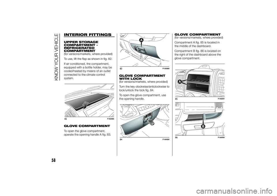
To use, lift the flap as shown in fig. 82.
If air conditioned, the compartment,
equipped with a bottle holder, may be
cooled/heated by means of an outlet
connected to the climate control
system.
GLOVE COMPARTMENT
To open the glove compartment,
operate the opening handle A fig. 83.GLOVE COMPARTMENT
WITH LOCK
(for versions/markets, where provided)
Turn the key clockwise/anticlockwise to
lock/unlock the lock fig. 84.
To open the glove compartment, use
the opening handle.GLOVE COMPARTMENT
(for versions/markets, where provided)
Compartment A fig. 85 is located in
the middle of the dashboard.
Compartment B fig. 86 is located on
the right of the dashboard above the
glove compartment.82
F1A0088
83
F1A0089
84
F1A0090
85
F1A0091
86
F1A0092
58
KNOW YOUR VEHICLE
Page 100 of 367
❒automatic climate control, if a
suitable thermal comfort level has not
yet been reached or MAX-DEF
function activation;
❒during the first period of use, to
initialise the system;
❒if the Hill Descent Control system is
active.
RESTARTING
CONDITIONS
For reasons of comfort, limiting harmful
emissions and safety purposes, the
power unit can restart automatically
without any action by the driver if
certain conditions are met, including:
❒battery not sufficiently charged;
❒reduced braking system vacuum
(e.g. if the brake pedal is pressed
repeatedly);
❒vehicle in motion (e.g. when driving
on roads with a gradient);
❒stopping the engine through the
Start&Stop system for more than
about three minutes.
❒automatic climate control system for
adjusting the thermal comfort level or
to enable MAX-DEF function.
With a gear engaged, the engine can
be automatically restarted only by
fully depressing the clutch pedal.NoteIf the engine stops and this is not
desired, due for example to the clutch
pedal being released sharply with a
gear engaged, if the Start&Stop system
is active, the engine can be restarted
by fully depressing the clutch pedal
or by placing the gear lever in neutral.
NoteIf the clutch is not pressed, when
approx. three minutes have elapsed
since the engine was stopped, the
engine can only be restarted using the
key.
SAFETY FUNCTIONS
In engine cut-out conditions through
the Start&Stop system, if the driver
unfastens his/her seat belt and opens
the driver's door or the passenger door,
the engine can be restarted only by
using the key. The driver is notified of
this condition by a buzzer, through the
warning light flashing in the
instrument panel and, where provided,
by a message in the display."ENERGY SAVING"
FUNCTION
(for versions/markets, where provided)
If, after the engine has been
automatically restarted, the driver does
not take any action for a period of
about 3 minutes, the Start&Stop
system will definitively stop the engine
to avoid fuel consumption. The engine
can only be started using the key in
such cases.
NoteIn any case, it is possible to keep
the engine running by deactivating
the Start&Stop system.
IRREGULAR OPERATION
In the event of malfunction, the
Start&Stop system is deactivated. The
driver is informed about the fault
through the switching on of the
icon
together with a message on the
display. In this case, contact a Fiat
Dealership.
96
KNOW YOUR VEHICLE
Page 101 of 367
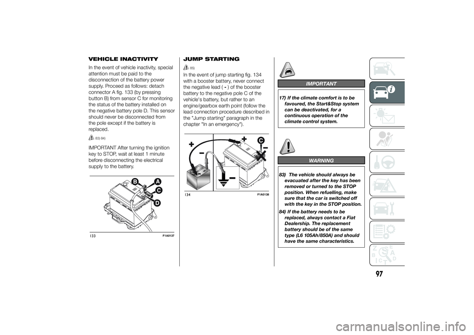
VEHICLE INACTIVITY
In the event of vehicle inactivity, special
attention must be paid to the
disconnection of the battery power
supply. Proceed as follows: detach
connector A fig. 133 (by pressing
button B) from sensor C for monitoring
the status of the battery installed on
the negative battery pole D. This sensor
should never be disconnected from
the pole except if the battery is
replaced.
83) 84)
IMPORTANT After turning the ignition
key to STOP, wait at least 1 minute
before disconnecting the electrical
supply to the battery.JUMP STARTING
85)
In the event of jump starting fig. 134
with a booster battery, never connect
the negative lead (-) of the booster
battery to the negative pole C of the
vehicle's battery, but rather to an
engine/gearbox earth point (follow the
lead connection procedure described in
the "Jump starting" paragraph in the
chapter "In an emergency").
IMPORTANT
17) If the climate comfort is to be
favoured, the Start&Stop system
can be deactivated, for a
continuous operation of the
climate control system.
WARNING
83) The vehicle should always be
evacuated after the key has been
removed or turned to the STOP
position. When refuelling, make
sure that the car is switched off
with the key in the STOP position.
84) If the battery needs to be
replaced, always contact a Fiat
Dealership. The replacement
battery should be of the same
type (L6 105Ah/850A) and should
have the same characteristics.
133
F1A0137
134
F1A0138
97
Page 112 of 367
SPEEDOMETER (speed
indicator)
Indicator A shows the speed of the car.
REV COUNTER
Indicator C shows the engine revs.
IMPORTANT The electronic injection
control system gradually shuts off
the flow of fuel when the engine
is over-revving, resulting in a gradual
loss of engine power.
When the engine is idling, the rev
counter may indicate a gradual or
sudden increase of the speed.
This is normal and does not indicate a
fault. It may be caused, for example, by
the activation of the climate control
system or fan. In these cases, a slow
change in revs is used to protect the
battery charge.
FUEL LEVEL GAUGE
Needle E shows the amount of fuel left
in the tank.
E - tank empty.
F - tank full (see the description in
paragraph "Vehicle refuelling" in this
chapter).The warning light on the indicator
switches on when there are about
10-12 litres of fuel (for versions with
tank capacity 90-120 l) or 10 l (for
versions with tank capacity 60 l)
remaining in the tank.
Do not travel with the tank nearly empty
to prevent damaging the catalytic
converter.
IMPORTANT The needle will point to E
and the warning light will flash to
indicate a fault in the system. If this is
the case, go to a Fiat Dealership to
have the system checked.
IMPORTANT It is not advisable to
activate the additional Webasto heater
in reserve conditions.
ENGINE COOLANT
TEMPERATURE
INDICATOR
The needle D shows the temperature of
the engine coolant and starts
supplying indications when the fluid
temperature exceeds approx. 50°C. In
normal use, the needle could assume
different positions within the scale,
depending on the usage conditions.
C - Low engine coolant temperature.
H - High engine coolant temperature.The warning light on the indicator may
light up (and a message on the display
may appear on certain versions) to
indicate that the coolant fluid
temperature is too high; in this case,
stop the engine and contact a Fiat
Dealership.
19)
ENGINE OIL LEVEL
GAUGE
(for versions/markets, where provided)
The gauge provides a graphic indication
of the level of oil in the engine.
When the ignition key is turned to
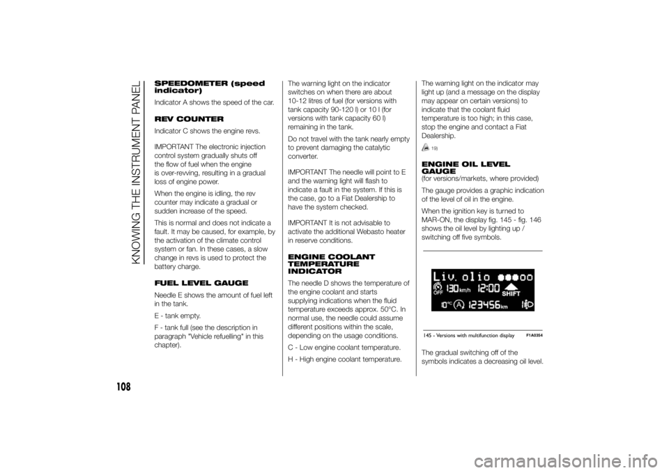
MAR-ON, the display fig. 145 - fig. 146
shows the oil level by lighting up /
switching off five symbols.
The gradual switching off of the
symbols indicates a decreasing oil level.145 - Versions with multifunction display
F1A0354
108
KNOWING THE INSTRUMENT PANEL
Page 116 of 367
- briefly press the MODE button to
store the new setting and go to the
next settings menu option. If this is the
last one, the system brings you back
to the previously selected menu option.
Press the button MODE for long:
- to exit the set-up menu if you are in
the main menu;
- to exit the main menu if you are in
another point of the menu (e.g.: at
submenu option setting level, at
submenu level or at main menu option
setting level);
- to save only the changes stored by
the user (and confirmed by pressing the
MODE button).
The setup menu environment is timed;
when the menu is exited due to expiry
of the time allowed, only the changes
already stored by the user (confirmed
beforehand by a brief press of the
MODE button) will be saved.
From the standard screen, briefly press
button MODE to start navigation.
Press the
or
buttons to
navigate within the menu.NoteOnly the reduced menu can be
accessed while the vehicle is moving
for safety reasons ("Speed Beep"
setting). Stop the vehicle to access the
full menu.
Lighting
(Passenger compartment light
adjustment)
(only with side lights on)
This function is used to set the
brightness of the instrument panel,
uconnect™system controls (for
versions/markets where provided) and
automatic climate control system
controls (for versions/markets where
provided) to 8 levels.
Proceed as follows to adjust the light
intensity:
❒briefly press the MODE button. The
level set previously flashes on the
display;
❒press button
or
to set
the required brightness level;
❒briefly press the MODE button to
return to the menu screen or hold the
button down to return to the
standard screen without storing.NoteOn versions with reconfigurable
multifunction display adjustment can be
made both with lights off ("daytime"
mode brightness level) and with lights
on ("nighttime" mode brightness level).
Headlight alignment
(Headlight alignment
corrector position
adjustment)
(for versions/markets, where provided)
This function permits the adjustment (to
4 levels) of the headlight alignment
corrector position.
To carry out the adjustment, proceed as
follows:
❒briefly press the MODE button. The
level set previously flashes on the
display;
❒press button
or
to adjust
the position;
❒briefly press the MODE button to
return to the menu screen or hold the
button down to return to the
standard screen without storing.
112
KNOWING THE INSTRUMENT PANEL
Page 180 of 367
SAVING FUELSome useful tips are given below for
fuel saving and reducing harmful
emissions of CO2 and other pollutants
(nitrogen oxides, unburnt
hydrocarbons, Particulate Matter (PM),
etc.).
GENERAL
CONSIDERATIONS
The general factors that affect fuel
consumption are listed below.
Vehicle maintenance
Have checks and adjustments carried
out in accordance with the “Scheduled
Servicing Plan”.Tyres
Check the tyre pressures at least once
every four weeks: if the pressure is
too low, consumption levels increase as
resistance to rolling is higher.
Unnecessary loads
Do not travel with an overloaded
luggage compartment. The weight of
the vehicle (especially when driving
in town) and its geometry greatly affect
fuel consumption and stability.
Roof rack/ski rack
Remove the roof rack or the ski rack
from the roof after use. These
accessories decrease aerodynamic
penetration of the vehicle and have a
negative effect on fuel consumption.
When transporting particularly large
objects, use a trailer if possible.Electric devices
Use electrical devices only for the
amount of time needed. The heated
rear window, additional headlights,
windscreen/rear window wipers and
heater fan need a considerable amount
of energy, therefore increasing fuel
consumption (by up to 25% in
the urban cycle).
Climate control system
Air conditioning leads to higher fuel
consumption (on average up to +20%).
If the temperature outside permits, try
and use the ventilation only.
Devices for
aerodynamic control
The use of non-certified spoilers may
adversely affect air drag and fuel
consumption.
176
STARTING AND DRIVING
Page 219 of 367
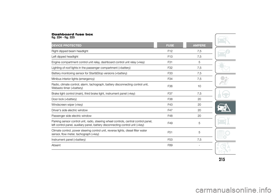
Dashboard fuse box
fig. 224 - fig. 225DEVICE PROTECTED FUSE AMPERERight dipped beam headlight F12 7,5
Left dipped headlight F13 7,5
Engine compartment control unit relay, dashboard control unit relay (+key) F31 5
Lighting of roof lights in the passenger compartment (+battery) F32 7,5
Battery monitoring sensor for Start&Stop versions (+battery) F33 7,5
Minibus interior lights (emergency) F34 7,5
Radio, climate control, alarm, tachograph, battery disconnecting control unit,
Webasto timer (+battery)F36 10
Brake light control (main), third brake light, instrument panel (+key) F37 7,5
Door lock (+battery) F38 20
Windscreen wiper (+key) F43 20
Driver's side electric window F47 20
Passenger side electric window F48 20
Parking sensor control unit, radio, steering wheel controls, central control panel,
left control panel, auxiliary panel, battery disconnecting control unit (+key)F49 5
Climate control, power steering control unit, reverse lights, diesel filter water
sensor, flow meter, tachograph (+key)F51 5
Instrument panel (+battery) F53 7,5
AbsentF89 -
215