spare wheel FIAT DUCATO BASE CAMPER 2014 Owner handbook (in English)
[x] Cancel search | Manufacturer: FIAT, Model Year: 2014, Model line: DUCATO BASE CAMPER, Model: FIAT DUCATO BASE CAMPER 2014Pages: 367, PDF Size: 20.39 MB
Page 86 of 367
❒interference caused by electronic
devices or radio frequency emissions
similar to those of the TPM sensors.
❒Application of tinted films which
interfere with the signals of the radio
waves.
❒Presence of snow or ice on the
wheels or the wheel arches.
❒Use of snow chains.
❒Use of wheels/tyres not equipped
with TPM sensors.
❒The space-saver wheel is not
equipped with the tyre pressure
control sensor. Therefore, the tyre
pressure is not controlled by the
system.
❒If the space-saver wheel replaces a
tyre with a pressure lower than the
insufficient pressure limit, an acoustic
signal will be emitted and the warning
light
will switch on at the next
ignition cycle.❒When the original tyre is repaired or
replaced and it is mounted back on
the vehicle to replace the space-
saver wheel, the TPMS will update
automatically and the warning light
will switch off, provided that the
pressure of none of the four tyres is
below the insufficient pressure limit.
You may need to drive the vehicle for
about 20 minutes at a speed higher
than 20 km/h to allow the TPMS
to receive this information.IMPORTANT
INFORMATION
WARNING
65) The TPMS is optimised for the
original tyres and wheels
provided. TPMS pressures and
alerts have been defined
according to the size of the tyres
mounted on the vehicle. Using
equipment with different size,
type or kind may cause irregular
system operation or sensor
damage. Non-original spare
wheels can damage the sensor.
Do not use tyre sealant or
balancing weights if the vehicle is
equipped with TPMS as these
may damage the sensors.
66) If the system signals a pressure
decrease on a specific tyre, it is
recommended to check the
pressure on all four tyres.
67) TPMS does not relieve the driver
from the obligation to check the
tyre pressure every month; it is
not even to be considered a
replacing system for maintenance
or a safety system.
82
KNOW YOUR VEHICLE
Page 195 of 367
BUMP STARTING
Never bump start the engine by
pushing, towing or driving downhill.
This could cause fuel to flow into the
catalytic converter and damage it
beyond repair.
WARNING
136) This procedure must be
performed by qualified personnel
as incorrect actions may cause
high-intensity electrical discharge.
Furthermore, battery fluid is
poisonous and corrosive: avoid
contact with skin and eyes. Keep
naked flames and lighted
cigarettes away from the battery
and do not cause sparks.
REPLACING A
WHEELGENERAL
INSTRUCTIONS
Wheel replacement and correct use of
the jack and spare wheel (for
versions/markets, where provided) call
for some precautions, which are listed
below.
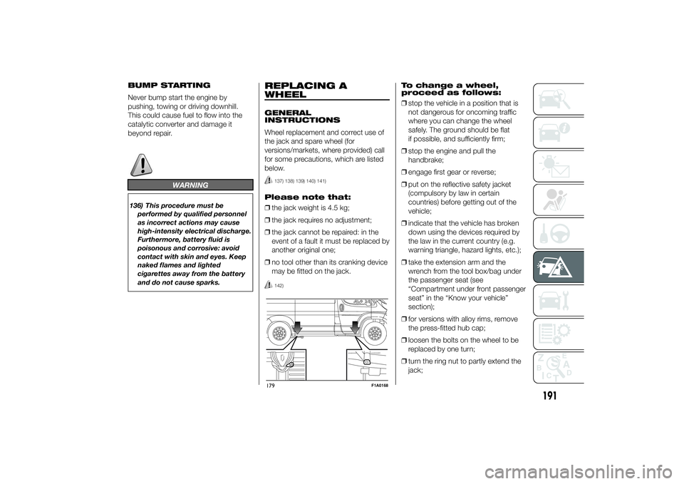
137) 138) 139) 140) 141)
Please note that:
❒the jack weight is 4.5 kg;
❒the jack requires no adjustment;
❒the jack cannot be repaired: in the
event of a fault it must be replaced by
another original one;
❒no tool other than its cranking device
may be fitted on the jack.
142)
To change a wheel,
proceed as follows:
❒stop the vehicle in a position that is
not dangerous for oncoming traffic
where you can change the wheel
safely. The ground should be flat
if possible, and sufficiently firm;
❒stop the engine and pull the
handbrake;
❒engage first gear or reverse;
❒put on the reflective safety jacket
(compulsory by law in certain
countries) before getting out of the
vehicle;
❒indicate that the vehicle has broken
down using the devices required by
the law in the current country (e.g.
warning triangle, hazard lights, etc.);
❒take the extension arm and the
wrench from the tool box/bag under
the passenger seat (see
“Compartment under front passenger
seat” in the “Know your vehicle”
section);
❒for versions with alloy rims, remove
the press-fitted hub cap;
❒loosen the bolts on the wheel to be
replaced by one turn;
❒turn the ring nut to partly extend the
jack;
179
F1A0168
191
Page 196 of 367
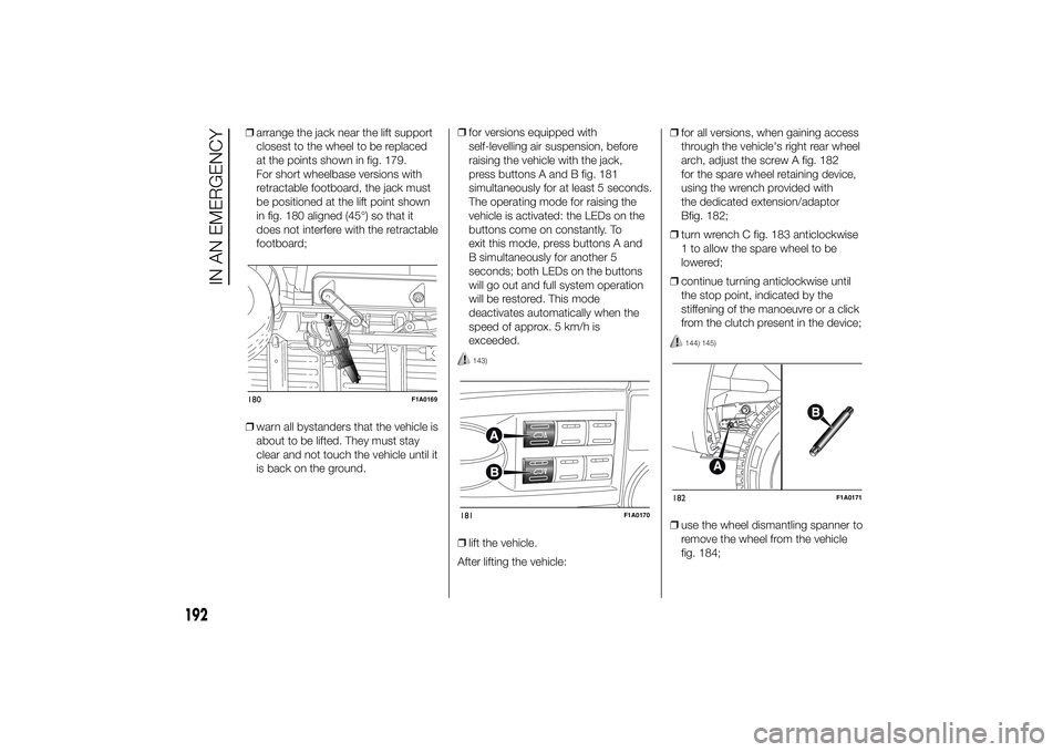
❒arrange the jack near the lift support
closest to the wheel to be replaced
at the points shown in fig. 179.
For short wheelbase versions with
retractable footboard, the jack must
be positioned at the lift point shown
in fig. 180 aligned (45°) so that it
does not interfere with the retractable
footboard;
❒warn all bystanders that the vehicle is
about to be lifted. They must stay
clear and not touch the vehicle until it
is back on the ground.❒for versions equipped with
self-levelling air suspension, before
raising the vehicle with the jack,
press buttons A and B fig. 181
simultaneously for at least 5 seconds.
The operating mode for raising the
vehicle is activated: the LEDs on the
buttons come on constantly. To
exit this mode, press buttons A and
B simultaneously for another 5
seconds; both LEDs on the buttons
will go out and full system operation
will be restored. This mode
deactivates automatically when the
speed of approx. 5 km/h is
exceeded.
143)
❒lift the vehicle.
After lifting the vehicle:❒for all versions, when gaining access
through the vehicle's right rear wheel
arch, adjust the screw A fig. 182
for the spare wheel retaining device,
using the wrench provided with
the dedicated extension/adaptor
Bfig. 182;
❒turn wrench C fig. 183 anticlockwise
1 to allow the spare wheel to be
lowered;
❒continue turning anticlockwise until
the stop point, indicated by the
stiffening of the manoeuvre or a click
from the clutch present in the device;
144) 145)
❒use the wheel dismantling spanner to
remove the wheel from the vehicle
fig. 184;
180
F1A0169
181
F1A0170
182
F1A0171
192
IN AN EMERGENCY
Page 197 of 367
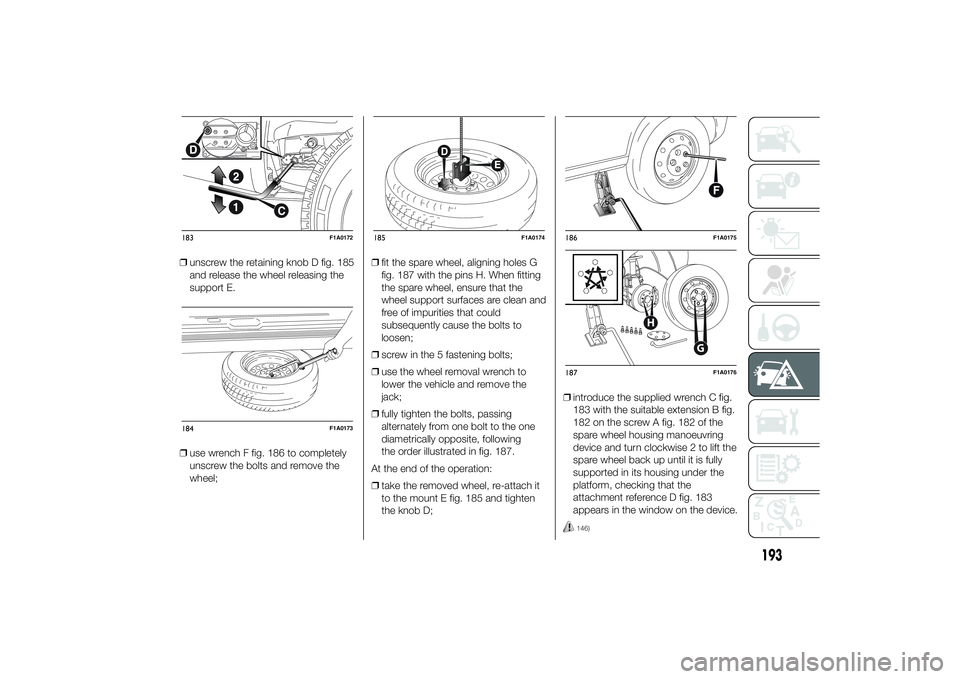
❒unscrew the retaining knob D fig. 185
and release the wheel releasing the
support E.
❒use wrench F fig. 186 to completely
unscrew the bolts and remove the
wheel;❒fit the spare wheel, aligning holes G
fig. 187 with the pins H. When fitting
the spare wheel, ensure that the
wheel support surfaces are clean and
free of impurities that could
subsequently cause the bolts to
loosen;
❒screw in the 5 fastening bolts;
❒use the wheel removal wrench to
lower the vehicle and remove the
jack;
❒fully tighten the bolts, passing
alternately from one bolt to the one
diametrically opposite, following
the order illustrated in fig. 187.
At the end of the operation:
❒take the removed wheel, re-attach it
to the mount E fig. 185 and tighten
the knob D;❒introduce the supplied wrench C fig.
183 with the suitable extension B fig.
182 on the screw A fig. 182 of the
spare wheel housing manoeuvring
device and turn clockwise 2 to lift the
spare wheel back up until it is fully
supported in its housing under the
platform, checking that the
attachment reference D fig. 183
appears in the window on the device.
146)
183
F1A0172
184
F1A0173
185
F1A0174
186
F1A0175
G
H
187
F1A0176
193
Page 198 of 367
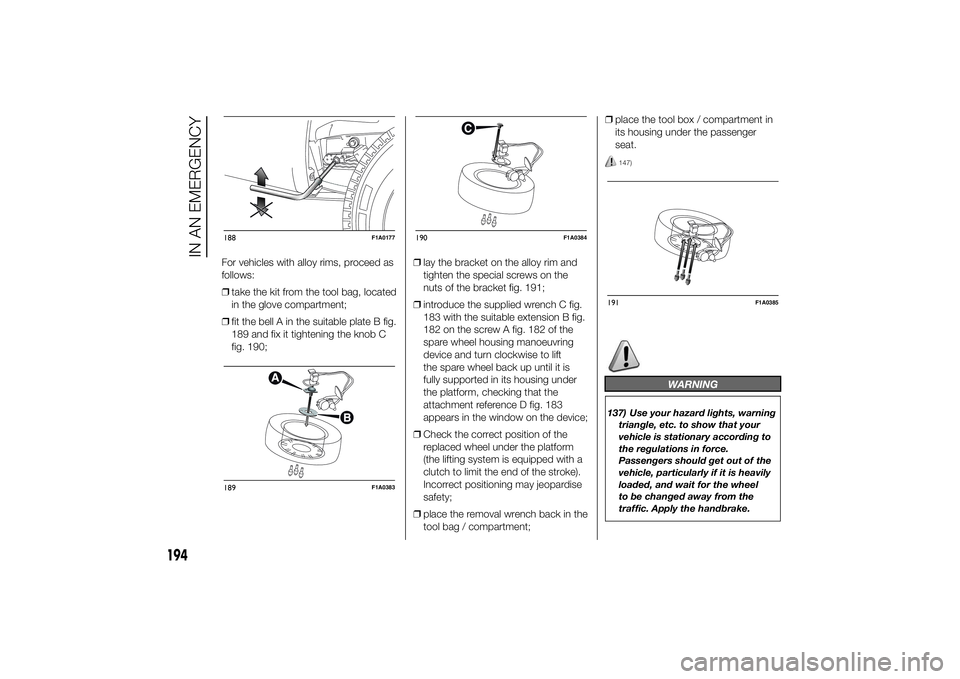
For vehicles with alloy rims, proceed as
follows:
❒take the kit from the tool bag, located
in the glove compartment;
❒fit the bell A in the suitable plate B fig.
189 and fix it tightening the knob C
fig. 190;❒lay the bracket on the alloy rim and
tighten the special screws on the
nuts of the bracket fig. 191;
❒introduce the supplied wrench C fig.
183 with the suitable extension B fig.
182 on the screw A fig. 182 of the
spare wheel housing manoeuvring
device and turn clockwise to lift
the spare wheel back up until it is
fully supported in its housing under
the platform, checking that the
attachment reference D fig. 183
appears in the window on the device;
❒Check the correct position of the
replaced wheel under the platform
(the lifting system is equipped with a
clutch to limit the end of the stroke).
Incorrect positioning may jeopardise
safety;
❒place the removal wrench back in the
tool bag / compartment;❒place the tool box / compartment in
its housing under the passenger
seat.
147)
WARNING
137) Use your hazard lights, warning
triangle, etc. to show that your
vehicle is stationary according to
the regulations in force.
Passengers should get out of the
vehicle, particularly if it is heavily
loaded, and wait for the wheel
to be changed away from the
traffic. Apply the handbrake.
188
F1A0177
189
F1A0383
190
F1A0384
191
F1A0385
194
IN AN EMERGENCY
Page 199 of 367
138) The spare wheel supplied (for
versions/markets, where
provided) is specific for your
vehicle. Therefore, it must not be
used on other models. Do not
use spare wheels of other models
on your vehicle. The wheel bolts
are specific for your vehicle: do
not use them on different models
and do not use bolts from other
models on your car.
139) Have the wheel repaired and
refitted as soon as possible. Do
not apply grease to the bolt
threads before fitting: they could
come unscrewed.
140) Use the jack only to replace
wheels on the vehicle with which
it is supplied or on other vehicles
of the same model. Never use
the jack for other purposes, such
as lifting other car models. Never
use the jack to carry out repairs
under the vehicle. Incorrect
positioning of the jack may cause
the lifted vehicle to fall. Do not
use the jack for loads higher than
those shown on the label.
141) Never tamper with the inflation
valve. Never introduce tools of any
kind between rim and tyre. Check
tyre and spare wheel pressure
regularly, referring to the values
shown in the "Technical
specifications" section.142) No tools other than the crank
provided should be used with
the spare wheel lifting device; it
should be operated by hand only.
143) On versions equipped with
self-levelling air suspension, never
introduce the head or hands in
the wheel arch: the vehicle could
raise or lower automatically
depending on possible load or
temperature changes.
144) The device should only be
operated by hand, without using
any type of tool other than the
crank provided, like pneumatic or
electrical screwers.
145) The moving components of the
jack (screw and joints) can also
cause injuries: do not touch them.
If you come into contact with
lubricating grease, clean yourself
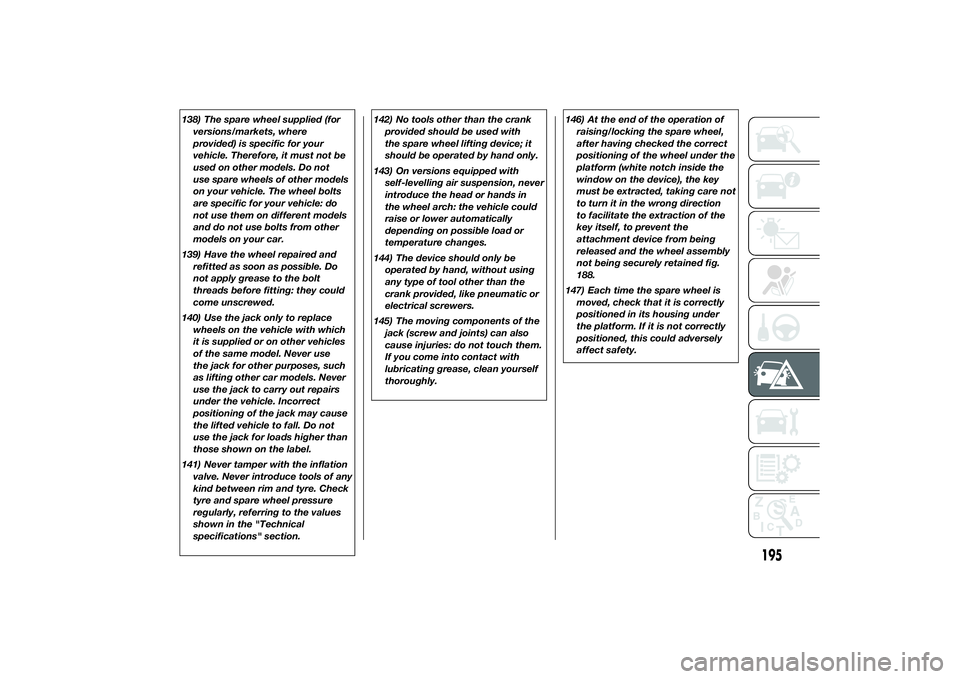
thoroughly.146) At the end of the operation of
raising/locking the spare wheel,
after having checked the correct
positioning of the wheel under the
platform (white notch inside the
window on the device), the key
must be extracted, taking care not
to turn it in the wrong direction
to facilitate the extraction of the
key itself, to prevent the
attachment device from being
released and the wheel assembly
not being securely retained fig.
188.
147) Each time the spare wheel is
moved, check that it is correctly
positioned in its housing under
the platform. If it is not correctly
positioned, this could adversely
affect safety.
195
Page 225 of 367
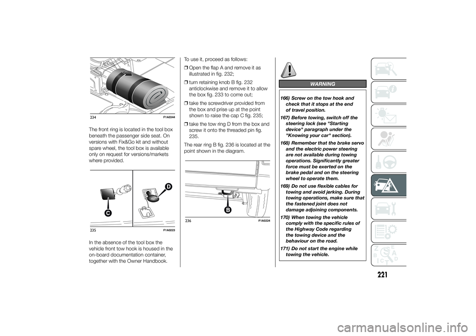
The front ring is located in the tool box
beneath the passenger side seat. On
versions with Fix&Go kit and without
spare wheel, the tool box is available
only on request for versions/markets
where provided.
In the absence of the tool box the
vehicle front tow hook is housed in the
on-board documentation container,
together with the Owner Handbook.To use it, proceed as follows:
❒Open the flap A and remove it as
illustrated in fig. 232;
❒turn retaining knob B fig. 232
anticlockwise and remove it to allow
the box fig. 233 to come out;
❒take the screwdriver provided from
the box and prise up at the point
shown to raise the cap C fig. 235;
❒take the tow ring D from the box and
screw it onto the threaded pin fig.
235.
The rear ring B fig. 236 is located at the
point shown in the diagram.
WARNING
166) Screw on the tow hook and
check that it stops at the end
of travel position.
167) Before towing, switch off the
steering lock (see "Starting
device" paragraph under the
"Knowing your car" section).
168) Remember that the brake servo
and the electric power steering
are not available during towing
operations. Significantly greater
force must be exerted on the
brake pedal and on the steering
wheel to operate them.
169) Do not use flexible cables for
towing and avoid jerking. During
towing operations, make sure that
the fastened joint does not
damage adjoining components.
170) When towing the vehicle
comply with the specific rules of
the Highway Code regarding
the towing device and the
behaviour on the road.
171) Do not start the engine while
towing the vehicle.
234
F1A0344
235
F1A0223
236
F1A0224
221
Page 244 of 367
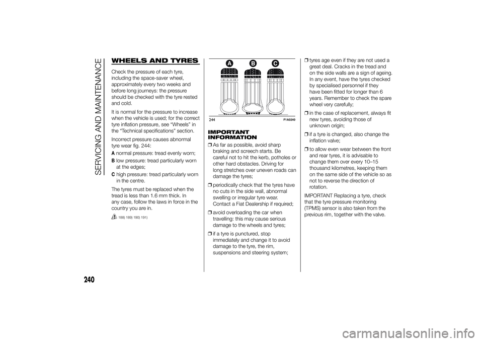
WHEELS AND TYRESCheck the pressure of each tyre,
including the space-saver wheel,
approximately every two weeks and
before long journeys: the pressure
should be checked with the tyre rested
and cold.
It is normal for the pressure to increase
when the vehicle is used; for the correct
tyre inflation pressure, see “Wheels” in
the “Technical specifications” section.
Incorrect pressure causes abnormal
tyre wear fig. 244:Anormal pressure: tread evenly worn;Blow pressure: tread particularly worn
at the edges;Chigh pressure: tread particularly worn
in the centre.
The tyres must be replaced when the
tread is less than 1.6 mm thick. In
any case, follow the laws in force in the
country you are in.188) 189) 190) 191)
IMPORTANT
INFORMATION
❒As far as possible, avoid sharp
braking and screech starts. Be
careful not to hit the kerb, potholes or
other hard obstacles. Driving for
long stretches over uneven roads can
damage the tyres;
❒periodically check that the tyres have
no cuts in the side wall, abnormal
swelling or irregular tyre wear.
Contact a Fiat Dealership if required;
❒avoid overloading the car when
travelling: this may cause serious
damage to the wheels and tyres;
❒if a tyre is punctured, stop
immediately and change it to avoid
damage to the tyre, the rim,
suspensions and steering system;❒tyres age even if they are not used a
great deal. Cracks in the tread and
on the side walls are a sign of ageing.
In any event, have the tyres checked
by specialised personnel if they
have been fitted for longer than 6
years. Remember to check the spare
wheel very carefully;
❒in the case of replacement, always fit
new tyres, avoiding those of
unknown origin;
❒if a tyre is changed, also change the
inflation valve;
❒to allow even wear between the front
and rear tyres, it is advisable to
change them over every 10–15
thousand kilometres, keeping them
on the same side of the vehicle so as
not to reverse the direction of
rotation.
IMPORTANT Replacing a tyre, check
that the tyre pressure monitoring
(TPMS) sensor is also taken from the
previous rim, together with the valve.244
F1A0240
240
SERVICING AND MAINTENANCE
Page 254 of 367
IDENTIFICATION
DATAIt is advisable to take note of the
identification codes. Identification codes
are printed and shown on the plates
as indicated below, together with the
positions:
❒VIN plate.
❒Chassis marking.
❒Bodywork paint identification plate.
❒Engine marking.
V.I.N. PLATE
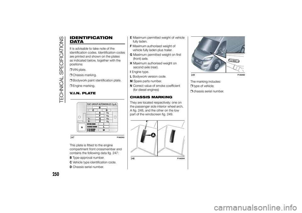
This plate is fitted to the engine
compartment front crossmember and
contains the following data fig. 247:BType-approval number.CVehicle type identification code.DChassis serial number.
EMaximum permitted weight of vehicle
fully laden.FMaximum authorised weight of
vehicle fully laden plus trailer.GMaximum permitted weight on first
(front) axle.HMaximum authorised weight on
second axle (rear).IEngine type.LBodywork version code.M
Spare parts number.
NCorrect value of smoke coefficient
(for diesel engines)
CHASSIS MARKING
They are located respectively: one on
the passenger side interior wheel arch,
A fig. 248, and the other on the low
part of the windscreen fig. 249.The marking includes:
❒type of vehicle;
❒chassis serial number.
247
F1A0243
248
F1A0244
249
F1A0365
250
TECHNICAL SPECIFICATIONS
Page 264 of 367
WHEELSRIMS AND TYRES
Pressed steel or alloy rims. Tubeless
radial carcass tyres. All approved tyres
are listed in the registration document.
IMPORTANT If there are any
discrepancies between the Owner
Handbook and the registration
document, take the information from
the latter.
For safe driving, the vehicle must be
fitted with tyres of the same make and
type on all wheels.
IMPORTANT Do not use air chambers
with tubeless tyres.
SPARE WHEEL
Pressed steel rim. Tubeless tyre.
WHEEL GEOMETRY
Front wheel toe-in measured from rim
to rim: -1±1mm.
The values refer to the vehicle in
running order.CORRECT READING OF
THE TYRE
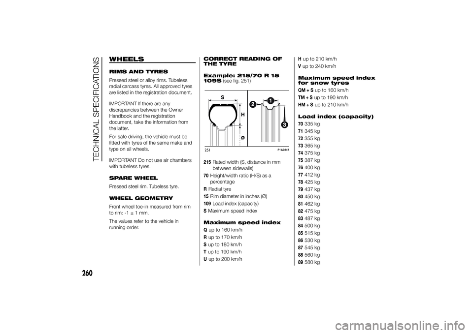
Example: 215/70 R 15
109S(see fig. 251)
215
Rated width (S, distance in mm
between sidewalls)
70
Height/width ratio (H/S) as a
percentage
RRadial tyre15
Rim diameter in inches (Ø)
109
Load index (capacity)
SMaximum speed index
Maximum speed indexQup to 160 km/hRup to 170 km/hSup to 180 km/hTup to 190 km/hUup to 200 km/h
Hup to 210 km/hVup to 240 km/h
Maximum speed index
for snow tyresQM+S
up to 160 km/h
TM+S
up to 190 km/h
HM+S
up to 210 km/h
Load index (capacity)
70
335 kg
71
345 kg
72
355 kg
73
365 kg
74
375 kg
75
387 kg
76
400 kg
77
412 kg
78
425 kg
79
437 kg
80
450 kg
81
462 kg
82
475 kg
83
487 kg
84
500 kg
85
515 kg
86
530 kg
87
545 kg
88
560 kg
89
580 kg
251
F1A0247
260
TECHNICAL SPECIFICATIONS