light FIAT DUCATO BASE CAMPER 2014 Owner handbook (in English)
[x] Cancel search | Manufacturer: FIAT, Model Year: 2014, Model line: DUCATO BASE CAMPER, Model: FIAT DUCATO BASE CAMPER 2014Pages: 367, PDF Size: 20.39 MB
Page 97 of 367
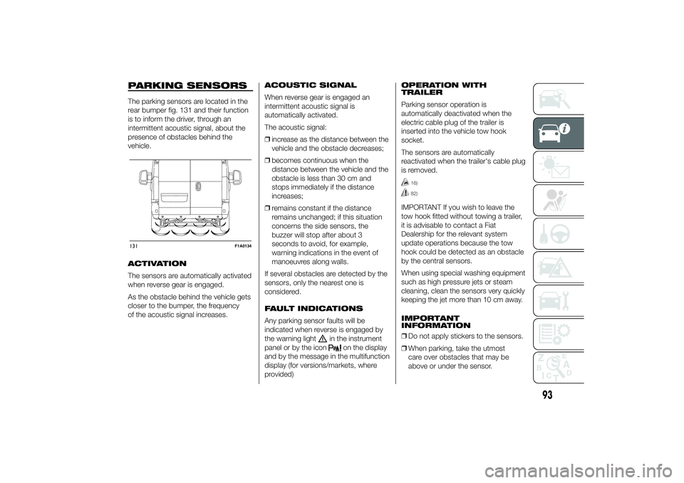
PARKING SENSORSThe parking sensors are located in the
rear bumper fig. 131 and their function
is to inform the driver, through an
intermittent acoustic signal, about the
presence of obstacles behind the
vehicle.
ACTIVATION
The sensors are automatically activated
when reverse gear is engaged.
As the obstacle behind the vehicle gets
closer to the bumper, the frequency
of the acoustic signal increases.ACOUSTIC SIGNAL
When reverse gear is engaged an
intermittent acoustic signal is
automatically activated.
The acoustic signal:
❒increase as the distance between the
vehicle and the obstacle decreases;
❒becomes continuous when the
distance between the vehicle and the
obstacle is less than 30 cm and
stops immediately if the distance
increases;
❒remains constant if the distance
remains unchanged; if this situation
concerns the side sensors, the
buzzer will stop after about 3
seconds to avoid, for example,
warning indications in the event of
manoeuvres along walls.
If several obstacles are detected by the
sensors, only the nearest one is
considered.
FAULT INDICATIONS
Any parking sensor faults will be
indicated when reverse is engaged by
the warning light
in the instrument
panel or by the icon
on the display
and by the message in the multifunction
display (for versions/markets, where
provided)OPERATION WITH
TRAILER
Parking sensor operation is
automatically deactivated when the
electric cable plug of the trailer is
inserted into the vehicle tow hook
socket.
The sensors are automatically
reactivated when the trailer's cable plug
is removed.
16)82)
IMPORTANT If you wish to leave the
tow hook fitted without towing a trailer,
it is advisable to contact a Fiat
Dealership for the relevant system
update operations because the tow
hook could be detected as an obstacle
by the central sensors.
When using special washing equipment
such as high pressure jets or steam
cleaning, clean the sensors very quickly
keeping the jet more than 10 cm away.
IMPORTANT
INFORMATION
❒Do not apply stickers to the sensors.
❒When parking, take the utmost
care over obstacles that may be
above or under the sensor.
131
F1A0134
93
Page 100 of 367
❒automatic climate control, if a
suitable thermal comfort level has not
yet been reached or MAX-DEF
function activation;
❒during the first period of use, to
initialise the system;
❒if the Hill Descent Control system is
active.
RESTARTING
CONDITIONS
For reasons of comfort, limiting harmful
emissions and safety purposes, the
power unit can restart automatically
without any action by the driver if
certain conditions are met, including:
❒battery not sufficiently charged;
❒reduced braking system vacuum
(e.g. if the brake pedal is pressed
repeatedly);
❒vehicle in motion (e.g. when driving
on roads with a gradient);
❒stopping the engine through the
Start&Stop system for more than
about three minutes.
❒automatic climate control system for
adjusting the thermal comfort level or
to enable MAX-DEF function.
With a gear engaged, the engine can
be automatically restarted only by
fully depressing the clutch pedal.NoteIf the engine stops and this is not
desired, due for example to the clutch
pedal being released sharply with a
gear engaged, if the Start&Stop system
is active, the engine can be restarted
by fully depressing the clutch pedal
or by placing the gear lever in neutral.
NoteIf the clutch is not pressed, when
approx. three minutes have elapsed
since the engine was stopped, the
engine can only be restarted using the
key.
SAFETY FUNCTIONS
In engine cut-out conditions through
the Start&Stop system, if the driver
unfastens his/her seat belt and opens
the driver's door or the passenger door,
the engine can be restarted only by
using the key. The driver is notified of
this condition by a buzzer, through the
warning light flashing in the
instrument panel and, where provided,
by a message in the display."ENERGY SAVING"
FUNCTION
(for versions/markets, where provided)
If, after the engine has been
automatically restarted, the driver does
not take any action for a period of
about 3 minutes, the Start&Stop
system will definitively stop the engine
to avoid fuel consumption. The engine
can only be started using the key in
such cases.
NoteIn any case, it is possible to keep
the engine running by deactivating
the Start&Stop system.
IRREGULAR OPERATION
In the event of malfunction, the
Start&Stop system is deactivated. The
driver is informed about the fault
through the switching on of the
icon
together with a message on the
display. In this case, contact a Fiat
Dealership.
96
KNOW YOUR VEHICLE
Page 105 of 367
When using or parking the vehicle for a
long time in the mountains or cold
areas, it is advisable to refuel using
locally available diesel fuel.
In this case, it is also advisable to keep
the tank over 50% full.
18)
FILLING THE TANK
To fill the tank completely, top-up twice
after the first click of the fuel supply
gun. Further top-ups could cause faults
in the fuel supply system.
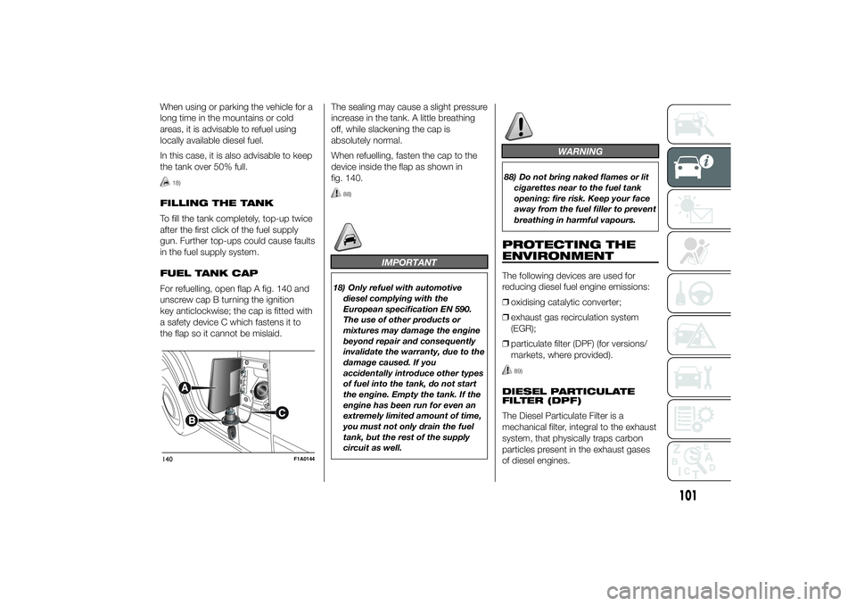
FUEL TANK CAP
For refuelling, open flap A fig. 140 and
unscrew cap B turning the ignition
key anticlockwise; the cap is fitted with
a safety device C which fastens it to
the flap so it cannot be mislaid.The sealing may cause a slight pressure
increase in the tank. A little breathing
off, while slackening the cap is
absolutely normal.
When refuelling, fasten the cap to the
device inside the flap as shown in
fig. 140.
88)
IMPORTANT
18) Only refuel with automotive
diesel complying with the
European specification EN 590.
The use of other products or
mixtures may damage the engine
beyond repair and consequently
invalidate the warranty, due to the
damage caused. If you
accidentally introduce other types
of fuel into the tank, do not start
the engine. Empty the tank. If the
engine has been run for even an
extremely limited amount of time,
you must not only drain the fuel
tank, but the rest of the supply
circuit as well.
WARNING
88) Do not bring naked flames or lit
cigarettes near to the fuel tank
opening: fire risk. Keep your face
away from the fuel filler to prevent
breathing in harmful vapours.PROTECTING THE
ENVIRONMENTThe following devices are used for
reducing diesel fuel engine emissions:
❒oxidising catalytic converter;
❒exhaust gas recirculation system
(EGR);
❒particulate filter (DPF) (for versions/
markets, where provided).
89)
DIESEL PARTICULATE
FILTER (DPF)
The Diesel Particulate Filter is a
mechanical filter, integral to the exhaust
system, that physically traps carbon
particles present in the exhaust gases
of diesel engines.
140
F1A0144
101
Page 106 of 367
The diesel particulate filter has been
adopted to eliminate almost all
particulates in compliance with current /
future legal regulations.
During normal use of the vehicle, the
Powertrain Control Module records
a set of data (travel time, type of route,
temperatures reached etc.) and
calculates how much particulate has
been trapped by the filter.
Since this filter physically traps
particulate, it should be regenerated
(cleaned) at regular intervals by burning
carbon particles.
The regeneration procedure is
controlled automatically by the
Powertrain Control Module according
to the filter conditions and vehicle
usage conditions.
During regeneration, the following may
occur: a limited increase in the engine
speed, activation of the fan, a limited
increase in fumes and high
temperatures at the exhaust.
These are not faults; they do not impair
vehicle performance or damage the
environment. If the dedicated message
is displayed, refer to paragraph
"Warning lights and messages".
WARNING
89) The diesel particulate filter (DPF)
reaches high temperatures during
normal operation. Do not park
the vehicle on flammable material
(grass, dry leaves, pine needles
etc.): fire hazard.
102
KNOW YOUR VEHICLE
Page 107 of 367
KNOWING THE INSTRUMENT PANEL
This section of the booklet gives you all
the information you need to
understand, interpret and use the
instrument panel correctly.CONTROL PANEL AND
INSTRUMENTS ...............................104
DISPLAY ........................................109
TRIP COMPUTER ...........................118
WARNING LIGHTS AND
MESSAGES ....................................121
- LOW BRAKE FLUID/HANDBRAKE
ENGAGED .......................................... 121
- EBD FAILURE .................................. 122
- AIRBAG FAILURE ............................. 122
- SEAT BELTS NOT FASTENED .......... 123
- ENGINE COOLANT TEMPERATURE
TOO HIGH .......................................... 124
- LOW BATTERY CHARGE ................. 124
- LOW ENGINE OIL PRESSURE ......... 125
-ENGINE OIL DETERIORATED ........... 125
-INCOMPLETE DOOR/LOAD
COMPARTMENT CLOSURE ............... 126
- POWER STEERING FAILURE ........... 126
-SELF-LEVELLING SUSPENSION
FAILURE ............................................. 126
- INJECTION/EOBD SYSTEM
FAILURE ............................................. 128
- ABS FAILURE ................................... 129
-FUEL RESERVE ................................ 129
- GLOW PLUG HEATING/GLOW
PLUG HEATING FAILURE ................... 130
- WATER IN DIESEL FILTER ................ 130
-VEHICLE PROTECTION SYSTEM
FAILURE - FIAT CODE ........................ 131
- REAR FOG LIGHTS .......................... 131
-GENERIC FAILURE INDICATION ....... 131
-DPF (PARTICULATE FILTER)
CLEANING UNDERWAY ..................... 133
-WORN BRAKE PADS ........................ 134
-DRIVING ADVISOR ........................... 135
- TPMS ............................................... 136
- DIPPED HEADLIGHTS ..................... 137- FOLLOW ME HOME ........................ 137
- LEFT-HAND DIRECTION INDICATOR
............................................................ 137
- RIGHT-HAND DIRECTION
INDICATOR ........................................ 138
-FOG LIGHTS ..................................... 138
- CRUISE CONTROL .......................... 138
-SPEED LIMITER ................................ 138
- AUTOMATIC MAIN BEAM
HEADLIGHTS ..................................... 139
- MAIN BEAM HEADLIGHTS .............. 139
-EXTERIOR LIGHTS FAULT ................ 140
-BRAKE LIGHT FAILURE .................... 140
-MAIN BEAM AUTOMATISM FAULT ... 141
-POSSIBLE ICE ON ROAD ................. 141
-SPEED LIMIT EXCEEDED ................. 141
-SCHEDULED SERVICING ................. 141
-DRIVING ADVISOR SYSTEM
FAILURE ............................................. 142
-TRAFFIC SIGN RECOGNITION
FAILURE ............................................. 142
-LIMITED RANGE ............................... 142
-START&STOP SYSTEM
ACTIVATION/DEACTIVATION .............. 143
-START&STOP FAILURE .................... 143
103
Page 108 of 367
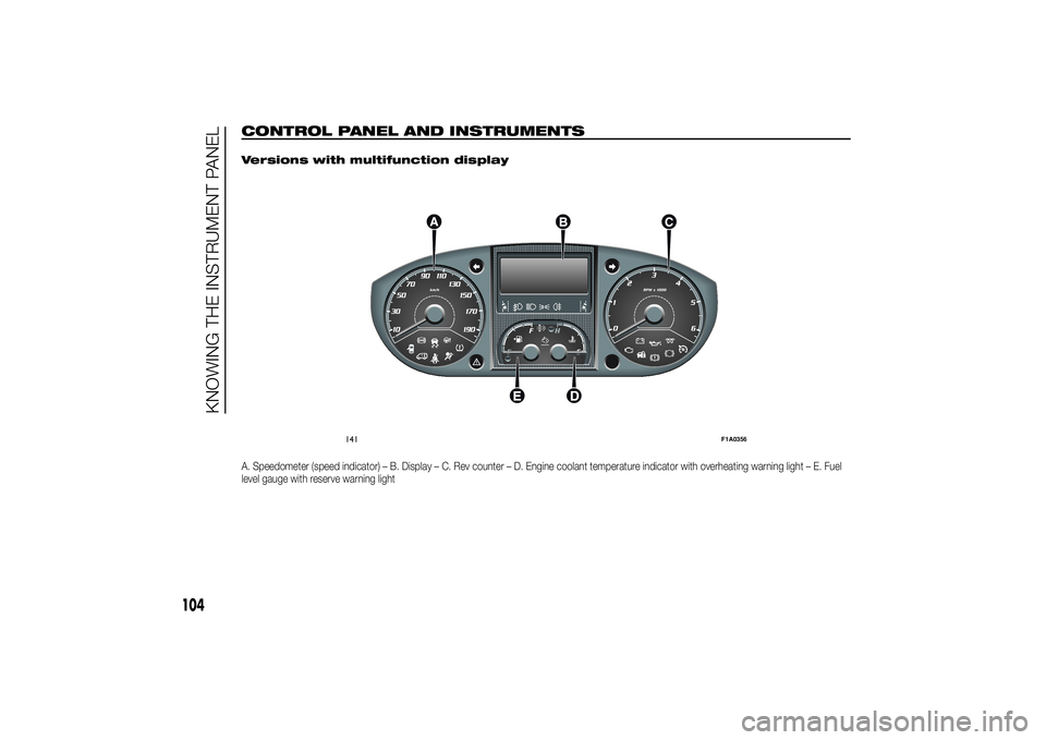
CONTROL PANEL AND INSTRUMENTS
.
Versions with multifunction displayA. Speedometer (speed indicator) – B. Display – C. Rev counter – D. Engine coolant temperature indicator with overheating warning light – E. Fuel
level gauge with reserve warning light
141
F1A0356
104
KNOWING THE INSTRUMENT PANEL
Page 109 of 367
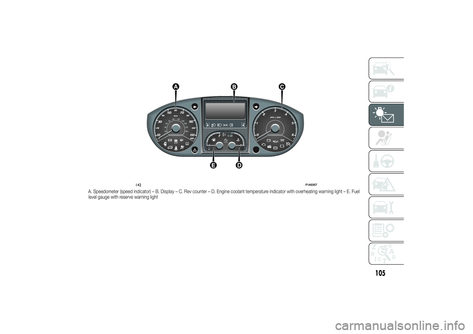
A. Speedometer (speed indicator) – B. Display – C. Rev counter – D. Engine coolant temperature indicator with overheating warning light – E. Fuel
level gauge with reserve warning light
142
F1A0357
105
Page 110 of 367
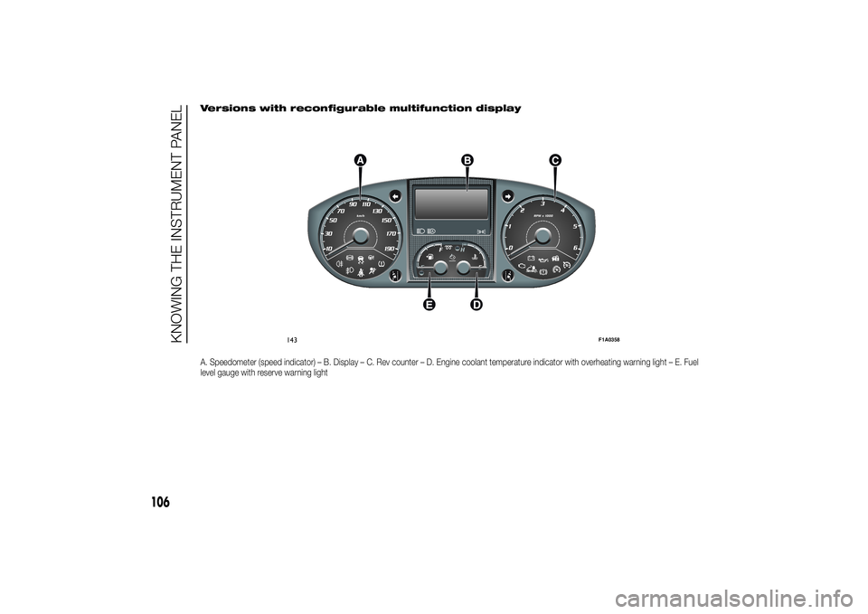
Versions with reconfigurable multifunction displayA. Speedometer (speed indicator) – B. Display – C. Rev counter – D. Engine coolant temperature indicator with overheating warning light – E. Fuel
level gauge with reserve warning light
143
F1A0358
106
KNOWING THE INSTRUMENT PANEL
Page 111 of 367
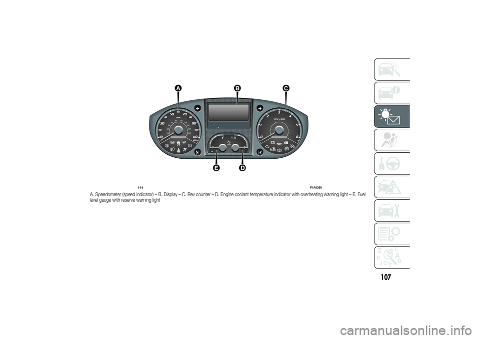
A. Speedometer (speed indicator) – B. Display – C. Rev counter – D. Engine coolant temperature indicator with overheating warning light – E. Fuel
level gauge with reserve warning light
144
F1A0359
107
Page 112 of 367
SPEEDOMETER (speed
indicator)
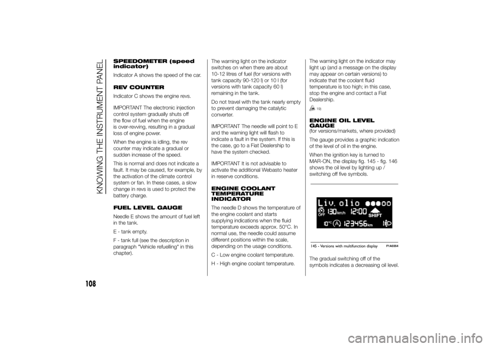
Indicator A shows the speed of the car.
REV COUNTER
Indicator C shows the engine revs.
IMPORTANT The electronic injection
control system gradually shuts off
the flow of fuel when the engine
is over-revving, resulting in a gradual
loss of engine power.
When the engine is idling, the rev
counter may indicate a gradual or
sudden increase of the speed.
This is normal and does not indicate a
fault. It may be caused, for example, by
the activation of the climate control
system or fan. In these cases, a slow
change in revs is used to protect the
battery charge.
FUEL LEVEL GAUGE
Needle E shows the amount of fuel left
in the tank.
E - tank empty.
F - tank full (see the description in
paragraph "Vehicle refuelling" in this
chapter).The warning light on the indicator
switches on when there are about
10-12 litres of fuel (for versions with
tank capacity 90-120 l) or 10 l (for
versions with tank capacity 60 l)
remaining in the tank.
Do not travel with the tank nearly empty
to prevent damaging the catalytic
converter.
IMPORTANT The needle will point to E
and the warning light will flash to
indicate a fault in the system. If this is
the case, go to a Fiat Dealership to
have the system checked.
IMPORTANT It is not advisable to
activate the additional Webasto heater
in reserve conditions.
ENGINE COOLANT
TEMPERATURE
INDICATOR
The needle D shows the temperature of
the engine coolant and starts
supplying indications when the fluid
temperature exceeds approx. 50°C. In
normal use, the needle could assume
different positions within the scale,
depending on the usage conditions.
C - Low engine coolant temperature.
H - High engine coolant temperature.The warning light on the indicator may
light up (and a message on the display
may appear on certain versions) to
indicate that the coolant fluid
temperature is too high; in this case,
stop the engine and contact a Fiat
Dealership.
19)
ENGINE OIL LEVEL
GAUGE
(for versions/markets, where provided)
The gauge provides a graphic indication
of the level of oil in the engine.
When the ignition key is turned to
MAR-ON, the display fig. 145 - fig. 146
shows the oil level by lighting up /
switching off five symbols.
The gradual switching off of the
symbols indicates a decreasing oil level.145 - Versions with multifunction display
F1A0354
108
KNOWING THE INSTRUMENT PANEL