FIAT DUCATO BASE CAMPER 2014 Owner handbook (in English)
Manufacturer: FIAT, Model Year: 2014, Model line: DUCATO BASE CAMPER, Model: FIAT DUCATO BASE CAMPER 2014Pages: 367, PDF Size: 20.39 MB
Page 61 of 367
FUEL CUT-OFF
SWITCHThe vehicle is fitted with a safety switch
that, in the event of a crash, comes
into operation by cutting off the fuel
supply and turning off the engine as a
consequence.When the inertia switch cuts in, it cuts
off the fuel supply and also activates
the hazard warning lights, side lights
and courtesy lights while releasing
all the doors and displaying the relevant
message; they are deactivated by
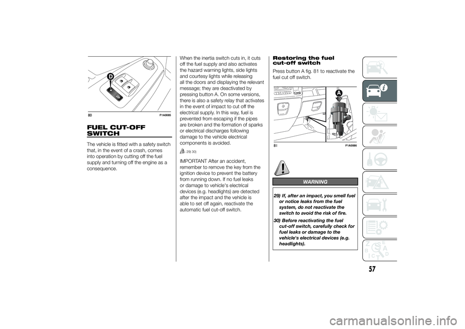
pressing button A. On some versions,
there is also a safety relay that activates
in the event of impact to cut off the
electrical supply. In this way, fuel is
prevented from escaping if the pipes
are broken and the formation of sparks
or electrical discharges following
damage to the vehicle electrical
components is avoided.
29) 30)
IMPORTANT After an accident,
remember to remove the key from the
ignition device to prevent the battery
from running down. If no fuel leaks
or damage to vehicle's electrical
devices (e.g. headlights) are detected
after the impact and the vehicle is
able to set off again, reactivate the
automatic fuel cut-off switch.Restoring the fuel
cut-off switch
Press button A fig. 81 to reactivate the
fuel cut off switch.
WARNING
29) If, after an impact, you smell fuel
or notice leaks from the fuel
system, do not reactivate the
switch to avoid the risk of fire.
30) Before reactivating the fuel
cut-off switch, carefully check for
fuel leaks or damage to the
vehicle's electrical devices (e.g.
headlights).
80
F1A0085
81
F1A0086
57
Page 62 of 367
INTERIOR FITTINGSUPPER STORAGE
COMPARTMENT -
REFRIGERATED
COMPARTMENT
(for versions/markets, where provided)
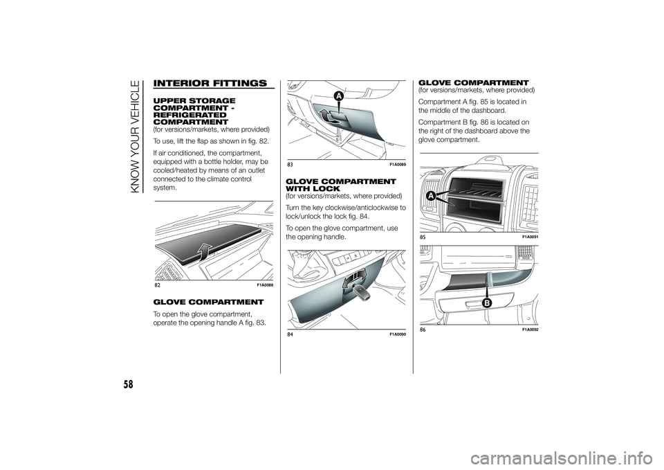
To use, lift the flap as shown in fig. 82.
If air conditioned, the compartment,
equipped with a bottle holder, may be
cooled/heated by means of an outlet
connected to the climate control
system.
GLOVE COMPARTMENT
To open the glove compartment,
operate the opening handle A fig. 83.GLOVE COMPARTMENT
WITH LOCK
(for versions/markets, where provided)
Turn the key clockwise/anticlockwise to
lock/unlock the lock fig. 84.
To open the glove compartment, use
the opening handle.GLOVE COMPARTMENT
(for versions/markets, where provided)
Compartment A fig. 85 is located in
the middle of the dashboard.
Compartment B fig. 86 is located on
the right of the dashboard above the
glove compartment.82
F1A0088
83
F1A0089
84
F1A0090
85
F1A0091
86
F1A0092
58
KNOW YOUR VEHICLE
Page 63 of 367
CUP HOLDER - CAN
HOLDER - BOTTLE
HOLDER ON
DASHBOARD
(for versions/markets, where provided)
On a few versions, two cup holders /
can holders / bottle holders (0.5 / 0.75
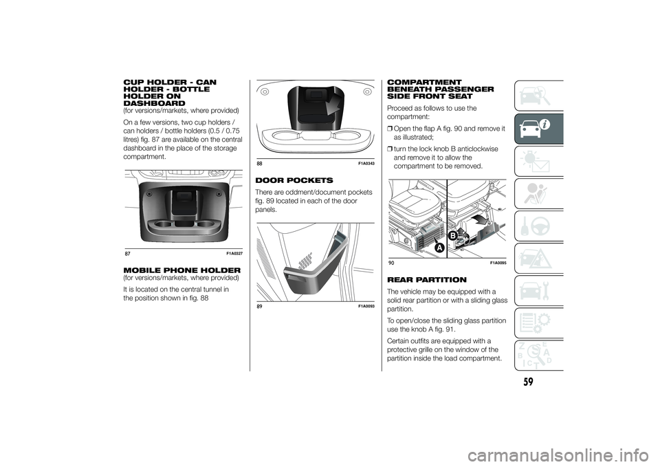
litres) fig. 87 are available on the central
dashboard in the place of the storage
compartment.
MOBILE PHONE HOLDER
(for versions/markets, where provided)
It is located on the central tunnel in
the position shown in fig. 88DOOR POCKETS
There are oddment/document pockets
fig. 89 located in each of the door
panels.COMPARTMENT
BENEATH PASSENGER
SIDE FRONT SEAT
Proceed as follows to use the
compartment:
❒Open the flap A fig. 90 and remove it
as illustrated;
❒turn the lock knob B anticlockwise
and remove it to allow the
compartment to be removed.
REAR PARTITION
The vehicle may be equipped with a
solid rear partition or with a sliding glass
partition.
To open/close the sliding glass partition
use the knob A fig. 91.
Certain outfits are equipped with a
protective grille on the window of the
partition inside the load compartment.87
F1A0327
88
F1A0343
89
F1A0093
90
F1A0095
59
Page 64 of 367
CUP HOLDER - CAN
HOLDER
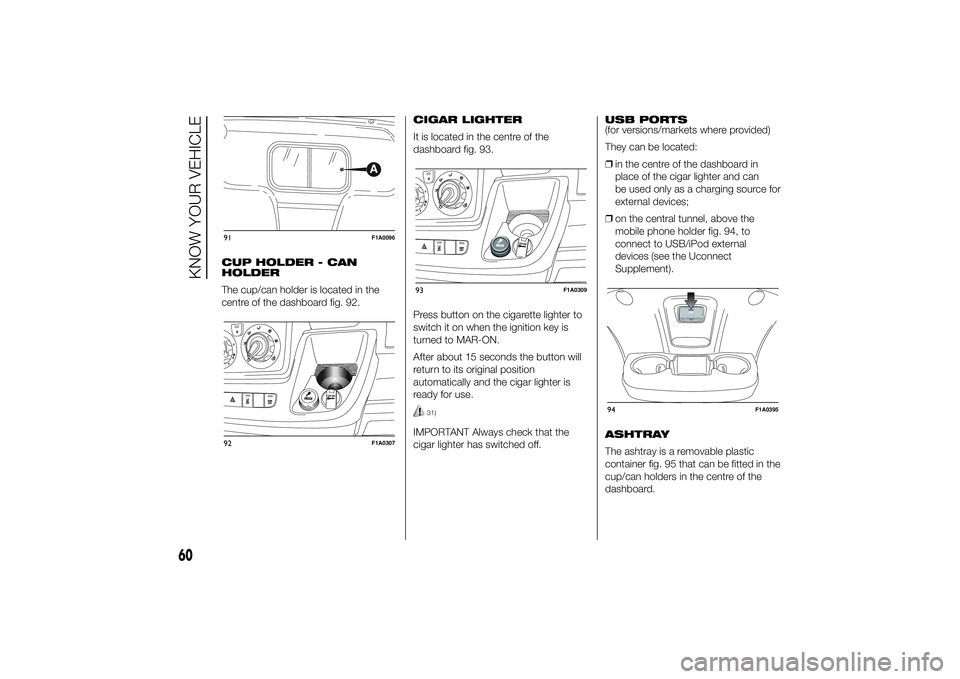
The cup/can holder is located in the
centre of the dashboard fig. 92.CIGAR LIGHTER
It is located in the centre of the
dashboard fig. 93.
Press button on the cigarette lighter to
switch it on when the ignition key is
turned to MAR-ON.
After about 15 seconds the button will
return to its original position
automatically and the cigar lighter is
ready for use.
31)
IMPORTANT Always check that the
cigar lighter has switched off.USB PORTS
(for versions/markets where provided)
They can be located:
❒in the centre of the dashboard in
place of the cigar lighter and can
be used only as a charging source for
external devices;
❒on the central tunnel, above the
mobile phone holder fig. 94, to
connect to USB/iPod external
devices (see the Uconnect
Supplement).
ASHTRAY
The ashtray is a removable plastic
container fig. 95 that can be fitted in the
cup/can holders in the centre of the
dashboard.
91
F1A0096
92
F1A0307
93
F1A0309
94
F1A0395
60
KNOW YOUR VEHICLE
Page 65 of 367
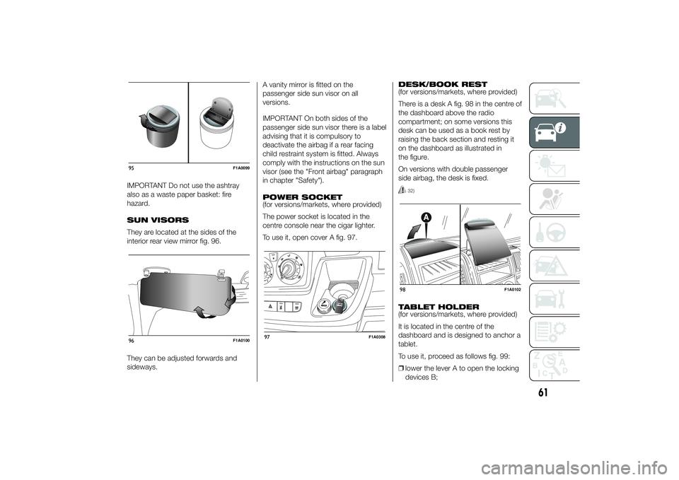
IMPORTANT Do not use the ashtray
also as a waste paper basket: fire
hazard.
SUN VISORS
They are located at the sides of the
interior rear view mirror fig. 96.
They can be adjusted forwards and
sideways.A vanity mirror is fitted on the
passenger side sun visor on all
versions.
IMPORTANT On both sides of the
passenger side sun visor there is a label
advising that it is compulsory to
deactivate the airbag if a rear facing
child restraint system is fitted. Always
comply with the instructions on the sun
visor (see the "Front airbag" paragraph
in chapter "Safety").
POWER SOCKET
(for versions/markets, where provided)
The power socket is located in the
centre console near the cigar lighter.
To use it, open cover A fig. 97.DESK/BOOK REST
(for versions/markets, where provided)
There is a desk A fig. 98 in the centre of
the dashboard above the radio
compartment; on some versions this
desk can be used as a book rest by
raising the back section and resting it
on the dashboard as illustrated in
the figure.
On versions with double passenger
side airbag, the desk is fixed.
32)
TABLET HOLDER
(for versions/markets, where provided)
It is located in the centre of the
dashboard and is designed to anchor a
tablet.
To use it, proceed as follows fig. 99:
❒lower the lever A to open the locking
devices B;
95
F1A0099
96
F1A0100
97
F1A0308
98
F1A0102
61
Page 66 of 367
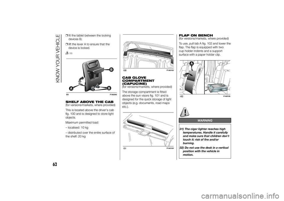
❒fit the tablet between the locking
devices B;
❒lift the lever A to ensure that the
device is locked.
33)
SHELF ABOVE THE CAB
(for versions/markets, where provided)
This is located above the driver's cab
fig. 100 and is designed to store light
objects.
Maximum permitted load:
– localised: 10 kg
– distributed over the entire surface of
the shelf: 20 kgCAB GLOVE
COMPARTMENT
(CAPUCINE)
(for versions/markets, where provided)
The storage compartment is fitted
above the sun visors fig. 101 and is
designed for the quick storage of light
objects (e.g. documents, road maps
etc.).FLAP ON BENCH
(for versions/markets, where provided)
To use, pull tab A fig. 102 and lower the
flap. The flap is equipped with two
cup holder indents and a support
surface with a paper holder clip.
WARNING
31) The cigar lighter reaches high
temperatures. Handle it carefully
and make sure that children don't
touch it: risk of fire and/or
burning.
32) Do not use the desk in a vertical
position with the vehicle in
motion.
99
F1A0342
100
F1A0103
101
F1A0104
102
F1A0105
62
KNOW YOUR VEHICLE
Page 67 of 367
33) To prevent dangerous situations,
moving the tablet holder and
using the device are prohibited
while driving.
TACHOGRAPHFor tachograph operation and use,
consult the owner handbook supplied
by the device manufacturer. The
tachograph must be installed on the
vehicle when the vehicle weight (with or
without trailer) exceeds 3.5 tons.
IMPORTANT Anyone making changes
to the monitoring device or signal
transmission system that affects
recording by the monitoring instrument,
particularly if this is done for purposes
of fraud, may be in breach of criminal or
administrative state regulations.
IMPORTANT If a tachograph is fitted, if
the vehicle is parked for more than 5
days, it is advisable to disconnect
the negative battery terminal to
maintain its charge.
IMPORTANT INFORMATION
Do not use abrasive detergents or
solvents to clean the device. To clean
the outside of the device, use a damp
cloth or special products for the care of
synthetic materials.The tachograph is installed and sealed
by authorised personnel: do not try
and access the device or the supply
and recording leads in any way. It is the
responsibility of the owner of the vehicle
on which the tachograph is installed to
check the device regularly.
The check must be carried out at least
every two years and a test must be
carried out to ensure that it is working
properly. Ensure that the data label
is renewed after every check and that
the label contains the specified data.
63
Page 68 of 367
SPEED BLOCK(for versions/markets, where provided)
The vehicle is equipped with a speed
limitation function that can be set at the
user's request to one of 4 predefined
values: 90, 100, 110, 130 km/h.
To activate/deactivate this function,
contact a Fiat Dealership.
Following the operation, a sticker will be
applied to the windscreen showing the
maximum speed setting.
IMPORTANT The speedometer could
indicate a higher maximum speed than
the effective one, set by the Dealership,
in accordance with the regulations in
force.
SELF-LEVELLING AIR
SUSPENSIONGENERAL INFORMATION
The system only acts on the rear
wheels.
The system maintains the rear ride
setting for the vehicle constant in any
loading condition, while ensuring a
greater driving comfort. In addition, the
system allows the height of the vehicle
to be adjusted with the vehicle
stationary, by selecting from 7 different
positions to facilitate access to the
rear compartment.
HEIGHT ADJUSTMENT
There are 7 pre-defined levels for the
free height from the ground: from “ride
-3” to “ride 0” till “ride +3”.
The multifunction display, located in the
middle of the instrument panel, can
show the ride position.
Automatic adjustment
When moving, the system automatically
shows that the vehicle is in 'ride setting
0' and keeps it constant.
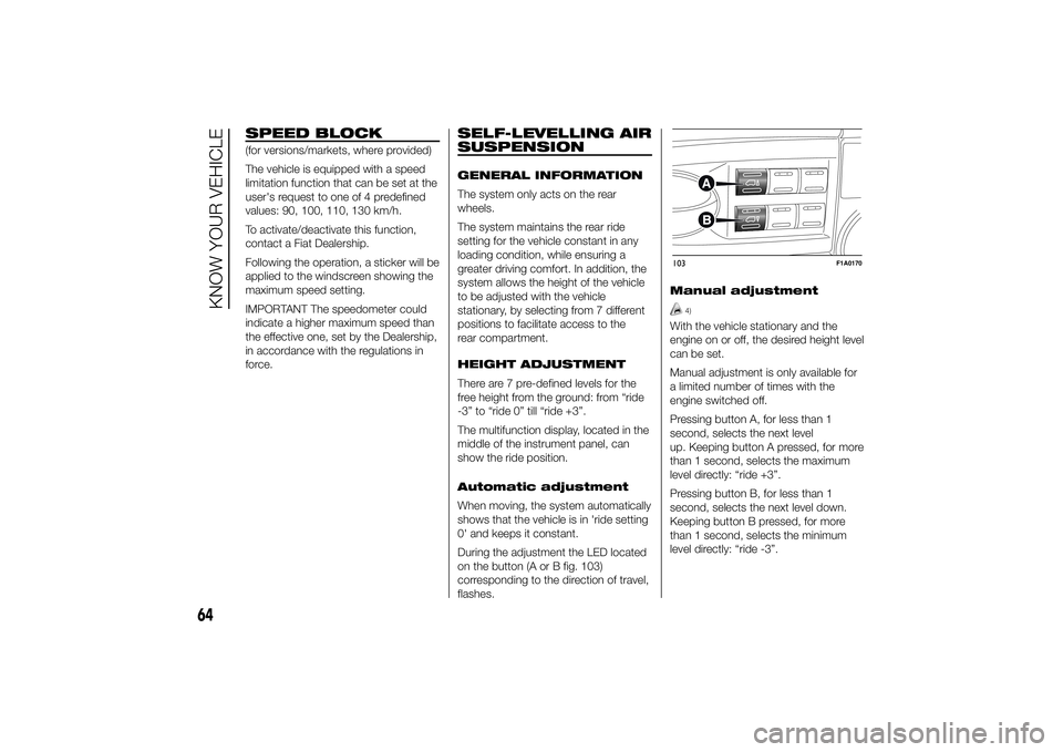
During the adjustment the LED located
on the button (A or B fig. 103)
corresponding to the direction of travel,
flashes.Manual adjustment
4)
With the vehicle stationary and the
engine on or off, the desired height level
can be set.
Manual adjustment is only available for
a limited number of times with the
engine switched off.
Pressing button A, for less than 1
second, selects the next level
up. Keeping button A pressed, for more
than 1 second, selects the maximum
level directly: “ride +3”.
Pressing button B, for less than 1
second, selects the next level down.
Keeping button B pressed, for more
than 1 second, selects the minimum
level directly: “ride -3”.103
F1A0170
64
KNOW YOUR VEHICLE
Page 69 of 367
During the adjustment the LED located
on the button (A or B) corresponding
to the direction of travel, flashes.
If, after selecting a button, the LED
remains lit up (for about 5 seconds)
rather than flashing, this means that the
adjustment is temporarily unavailable.
Possible causes may be as follows:
❒insufficient air reserve: the function is
restored by starting the engine;
❒the system has reached a threshold
working temperature: wait a few
minutes to let it cool down before
operating the buttons again.
The level selected with the vehicle
stationary is maintained up to a speed
of about 20 km/h; when this speed
is exceeded, the system will
automatically restore the normal level:
“ride 0”.
IMPORTANT
4) Before manually adjusting with
doors open, make sure there is
enough space around the vehicle
for this kind of operation.
DOORSDOOR CENTRAL
LOCKING/UNLOCKING
Locking doors from the
outside
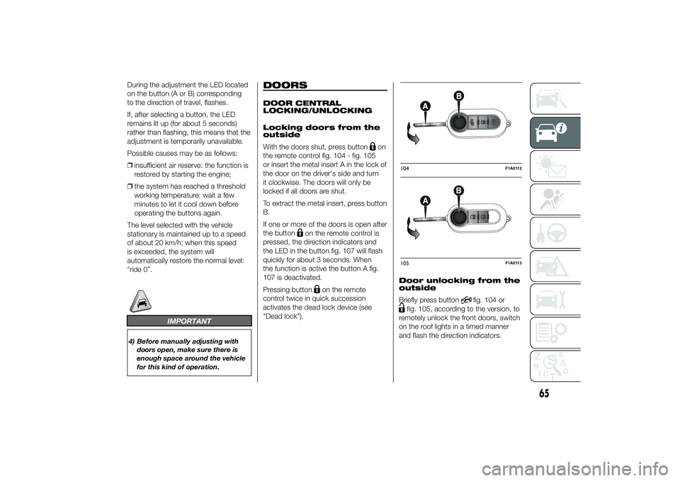
With the doors shut, press button
on
the remote control fig. 104 - fig. 105
or insert the metal insert A in the lock of
the door on the driver's side and turn
it clockwise. The doors will only be
locked if all doors are shut.
To extract the metal insert, press button
B.
If one or more of the doors is open after
the button
on the remote control is
pressed, the direction indicators and
the LED in the button fig. 107 will flash
quickly for about 3 seconds. When
the function is active the button A fig.
107 is deactivated.
Pressing button
on the remote
control twice in quick succession
activates the dead lock device (see
"Dead lock").Door unlocking from the
outside
Briefly press button
fig. 104 or
fig. 105, according to the version, to
remotely unlock the front doors, switch
on the roof lights in a timed manner
and flash the direction indicators.104
F1A0112
105
F1A0113
65
Page 70 of 367
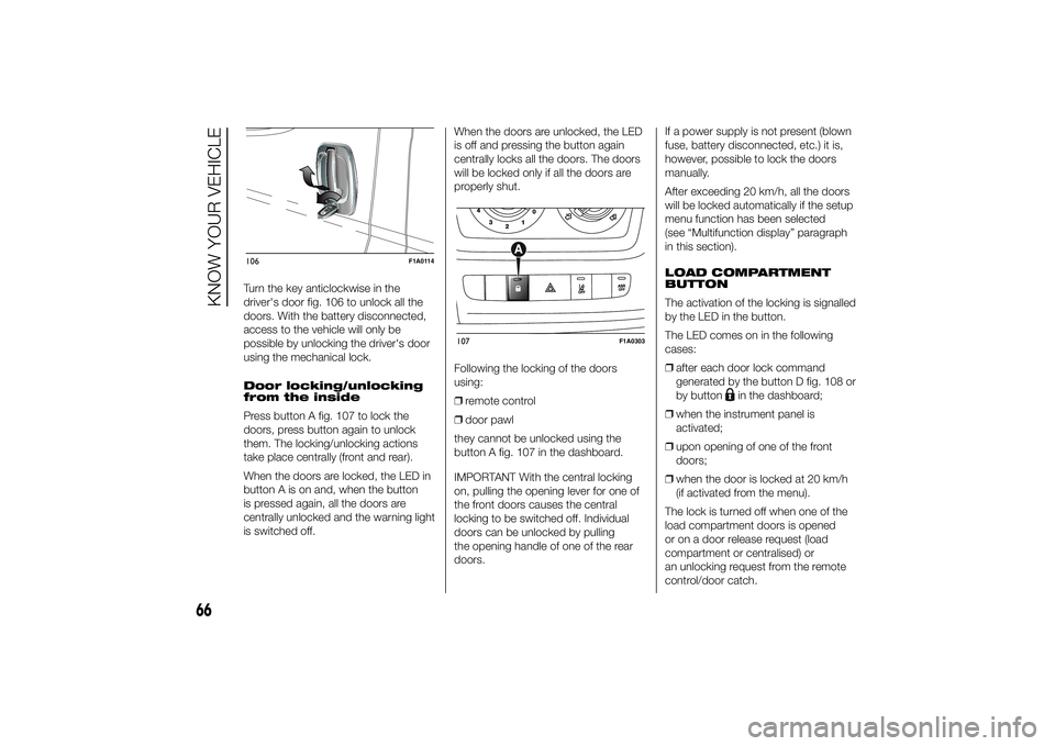
Turn the key anticlockwise in the
driver's door fig. 106 to unlock all the
doors. With the battery disconnected,
access to the vehicle will only be
possible by unlocking the driver's door
using the mechanical lock.
Door locking/unlocking
from the inside
Press button A fig. 107 to lock the
doors, press button again to unlock
them. The locking/unlocking actions
take place centrally (front and rear).
When the doors are locked, the LED in
button A is on and, when the button
is pressed again, all the doors are
centrally unlocked and the warning light
is switched off.When the doors are unlocked, the LED
is off and pressing the button again
centrally locks all the doors. The doors
will be locked only if all the doors are
properly shut.
Following the locking of the doors
using:
❒remote control
❒door pawl
they cannot be unlocked using the
button A fig. 107 in the dashboard.
IMPORTANT With the central locking
on, pulling the opening lever for one of
the front doors causes the central
locking to be switched off. Individual
doors can be unlocked by pulling
the opening handle of one of the rear
doors.If a power supply is not present (blown
fuse, battery disconnected, etc.) it is,
however, possible to lock the doors
manually.
After exceeding 20 km/h, all the doors
will be locked automatically if the setup
menu function has been selected
(see “Multifunction display” paragraph
in this section).
LOAD COMPARTMENT
BUTTON
The activation of the locking is signalled
by the LED in the button.
The LED comes on in the following
cases:
❒after each door lock command
generated by the button D fig. 108 or
by button
in the dashboard;
❒when the instrument panel is
activated;
❒upon opening of one of the front
doors;
❒when the door is locked at 20 km/h
(if activated from the menu).
The lock is turned off when one of the
load compartment doors is opened
or on a door release request (load
compartment or centralised) or
an unlocking request from the remote
control/door catch.
106
F1A0114
107
F1A0303
66
KNOW YOUR VEHICLE