turn signal FIAT DUCATO BASE CAMPER 2014 Owner handbook (in English)
[x] Cancel search | Manufacturer: FIAT, Model Year: 2014, Model line: DUCATO BASE CAMPER, Model: FIAT DUCATO BASE CAMPER 2014Pages: 367, PDF Size: 20.39 MB
Page 14 of 367
SYMBOLSSome vehicle components have
coloured labels whose symbols indicate
precautions to be observed when
using this component. Under the
bonnet there is also a label that
summarises all the symbols.
THE FIAT CODE
SYSTEM
IN BRIEF
This is an electrical engine locking
system which increases protection
against attempted theft of the vehicle.
It is automatically activated when
the ignition key is removed.
Each key contains an electronic
device which modulates the signal
emitted during ignition by an antenna
built into the ignition device. The
signal, which changes each time the
engine is started, is the “password”,
by means of which the control unit
recognises the key and enables
starting.
1)
Operation
Each time the vehicle is started turning
the ignition key toMAR-ON, the Fiat
CODE system control unit sends a
recognition code to the Powertrain
Control Module to deactivate the
immobiliser.The acknowledgement code is sent
only if the Fiat CODE system control
unit has recognised the code
transmitted from the key.
Each time the ignition key is turned to
STOP, the Fiat CODE system
deactivates the functions of the
Powertrain Control Module.
Irregular operation
If, during starting, the code has not
been recognised correctly the warning
light
on the instrument panel turns
on accompanied by the related
message on the display (see section
“Warning lights and messages”).
In this case, turn the key toSTOPand
then back toMAR-ON; if the lock
continues, try with the other keys
provided with the vehicle. Contact a
Fiat Dealership if you still cannot start
the engine.
IMPORTANT Each key has its own
code which must be stored by the
system's control unit. Contact the Fiat
Dealership to have new keys (up to
eight) stored with the code.
10
KNOW YOUR VEHICLE
Page 17 of 367
IMPORTANT
1) Used batteries are harmful to the
environment. You can dispose of
them either in the correct
containers as specified by law or
by taking them to a Fiat
Dealership, which will deal with
their disposal.
ELECTRONIC ALARM(for versions/markets, where provided)
The alarm, in addition to all the remote
control functions described previously,
is controlled by the receiver located
under the dashboard near the fuse box.
Operation
The alarm intervenes in the following
cases:
❒wrongful opening of a door or the
bonnet (perimeter protection);
❒when the ignition system is started
up (ignition key turned to MAR-ON);
❒cutting of the battery leads.
Depending on the market, the
activation of the alarm causes the
activation of the siren and the direction
indicators (for about 26 seconds).
Alarm tripping and the number of
cycles depend on the sales market.
There is a maximum number of
acoustic/visual cycles. When this is
reached the system returns to normal
operation.
IMPORTANT The engine stop function
is guaranteed by the Fiat CODE, which
is automatically activated when the
ignition key is extracted from the
ignition switch.Activation
With the doors and bonnet closed and
the ignition key either turned to STOP
or removed, point the key with the
remote control towards the vehicle and
press and release the lock button.
Excluding some markets, the system
produces an acoustic warning (beep)
and enables door locking.
The switching on of the alarm is
preceded by an self-diagnosis stage: if
a fault is detected, the system
produces another acoustic signal.
In this case, turn the alarm off by
pressing the "release doors/release
load compartment" button, check that
the doors and bonnet are properly
closed and turn the alarm back on by
pressing the lock button.
If a door or the bonnet is not properly
shut, it will be excluded from the testing
by the alarm system.
If the alarm produces an acoustic signal
even when the doors and bonnet are
correctly closed, a fault has occurred in
the operation of the system. Contact
a Fiat Dealership.
IMPORTANT The alarm does not come
on when the central locking is activated
using the metal insert in the key.
13
Page 18 of 367
IMPORTANT The alarm is adapted to
meet requirements in various countries.
Disengagement
Press the door release/load
compartment release button on the key
with remote control.
The following operations are performed
(excluding some markets):
❒direction indicators flash twice;
❒there are two short acoustic signals
(beeps);
❒unlocking of the doors.
IMPORTANT The alarm does not switch
off when the central opening is
activated using the metal insert in the
key.
Break-in attempt
indication
Any break-in attempt is indicated by the
turning on of warning light
on the
instrument panel together with the
message on the display (where
provided, see paragraph “Warning
lights and messages” in the “Knowing
the instrument panel” section).Disabling
To permanently disable the alarm (e.g.
during a long period of inactivity), simply
lock the vehicle by turning the metal
insert of the key with remote control in
the lock.
IMPORTANT If the batteries of the key
with the remote control run out or
the system fails, the alarm can
be switched off by placing the key in
the ignition switch and turning it to
MAR-ON.
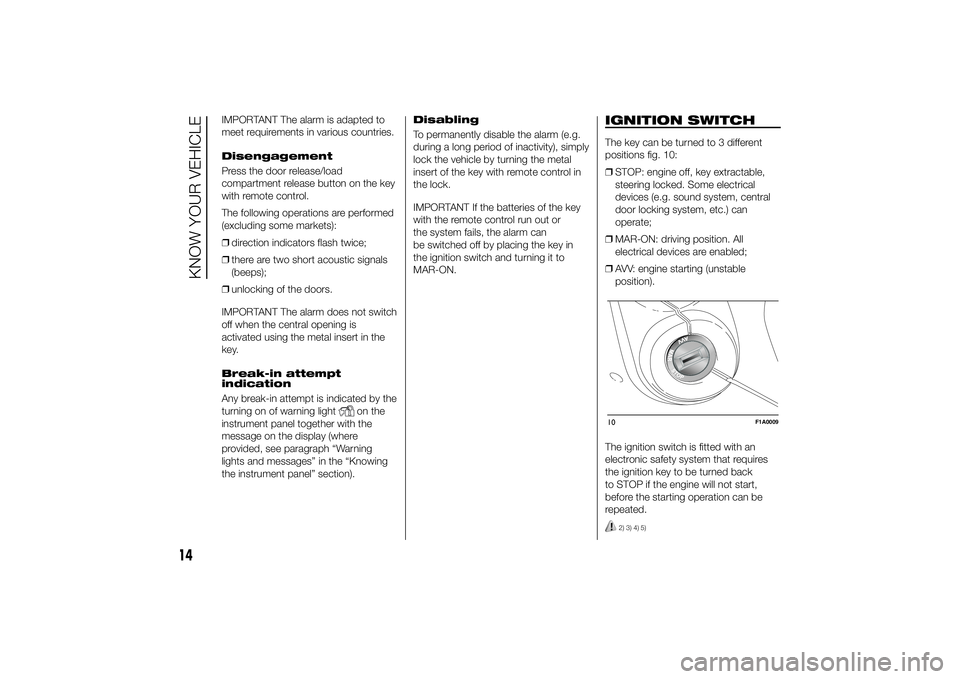
IGNITION SWITCHThe key can be turned to 3 different
positions fig. 10:
❒STOP: engine off, key extractable,
steering locked. Some electrical
devices (e.g. sound system, central
door locking system, etc.) can
operate;
❒MAR-ON: driving position. All
electrical devices are enabled;
❒AVV: engine starting (unstable
position).
The ignition switch is fitted with an
electronic safety system that requires
the ignition key to be turned back
to STOP if the engine will not start,
before the starting operation can be
repeated.
2) 3) 4) 5)
10
F1A0009
14
KNOW YOUR VEHICLE
Page 50 of 367
If the stalk is pulled again in this
condition, to request main beam
headlight deactivation, the function
remains off and the main beam
headlights switch off.
Rotate the ring nut to the position
fig. 58 to deactivate the automatic
function.25) 24)
PARKING LIGHTS
These lights can only be turned on with
ignition key in STOP position or
removed, by moving the left stalk ring
nut first to positionOand then to
position
or
.
The
warning light switches on in
the instrument panel.
DIRECTION INDICATORS
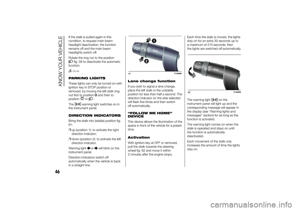
Bring the stalk into (stable) position fig.
61:
❒up (position 1): to activate the right
direction indicator;
❒down (position 2): to activate the left
direction indicator.
Warning light
or
will blink on the
instrument panel.
Direction indicators switch off
automatically when the vehicle is back
in a straight line.Lane change function
If you wish to signal a lane change,
place the left stalk in the unstable
position for less than half a second. The
direction indicator on the side selected
will flash five times and then switch
off automatically.
“FOLLOW ME HOME”
DEVICE
This device allows the illumination of the
space in front of the vehicle for a preset
time.
Activation
With ignition key at OFF or removed,
pull the stalk towards the steering
wheel fig. 62 and move it within
2 minutes after the engine stops.Each time the stalk is moved, the lights
stay on for an extra 30 seconds up to
a maximum of 210 seconds; then
the lights are switched off automatically.
The warning light
on the
instrument panel will light up and the
corresponding message will appear in
the display (see “Warning lights and
messages” section) for as long as the
function is activated.
The warning light comes on when the
stalk is operated and stays on until
the function is automatically
deactivated.
Each movement of the stalk only
increases the amount of time the lights
stay on.
61
F1A0068
62
F1A0069
46
KNOW YOUR VEHICLE
Page 53 of 367
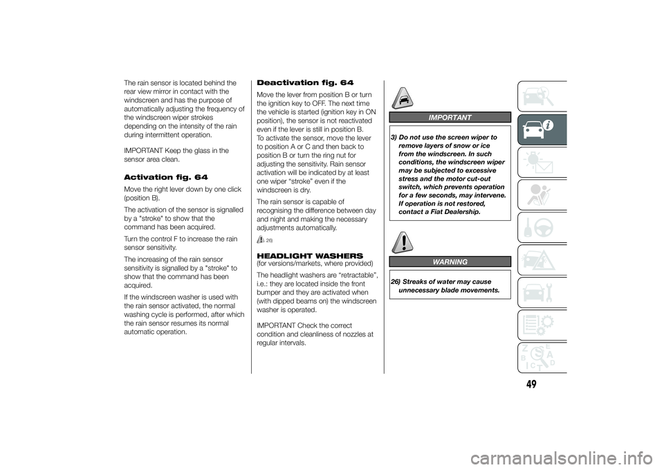
The rain sensor is located behind the
rear view mirror in contact with the
windscreen and has the purpose of
automatically adjusting the frequency of
the windscreen wiper strokes
depending on the intensity of the rain
during intermittent operation.
IMPORTANT Keep the glass in the
sensor area clean.
Activation fig. 64
Move the right lever down by one click
(position B).
The activation of the sensor is signalled
by a "stroke" to show that the
command has been acquired.
Turn the control F to increase the rain
sensor sensitivity.
The increasing of the rain sensor
sensitivity is signalled by a "stroke" to
show that the command has been
acquired.
If the windscreen washer is used with
the rain sensor activated, the normal
washing cycle is performed, after which
the rain sensor resumes its normal
automatic operation.Deactivation fig. 64
Move the lever from position B or turn
the ignition key to OFF. The next time
the vehicle is started (ignition key in ON
position), the sensor is not reactivated
even if the lever is still in position B.
To activate the sensor, move the lever
to position A or C and then back to
position B or turn the ring nut for
adjusting the sensitivity. Rain sensor
activation will be indicated by at least
one wiper “stroke” even if the
windscreen is dry.
The rain sensor is capable of
recognising the difference between day
and night and making the necessary
adjustments automatically.
26)
HEADLIGHT WASHERS
(for versions/markets, where provided)
The headlight washers are “retractable”,
i.e.: they are located inside the front
bumper and they are activated when
(with dipped beams on) the windscreen
washer is operated.
IMPORTANT Check the correct
condition and cleanliness of nozzles at
regular intervals.
IMPORTANT
3) Do not use the screen wiper to
remove layers of snow or ice
from the windscreen. In such
conditions, the windscreen wiper
may be subjected to excessive
stress and the motor cut-out
switch, which prevents operation
for a few seconds, may intervene.
If operation is not restored,
contact a Fiat Dealership.
WARNING
26) Streaks of water may cause
unnecessary blade movements.
49
Page 56 of 367
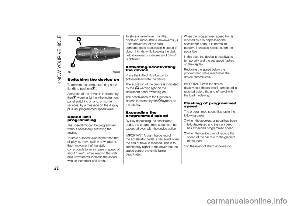
Switching the device on
To activate the device, turn ring nut A
fig. 68 to position
.
Activation of the device is indicated by
the
warning light on the instrument
panel switching on and, on some
versions, by a message on the display
plus last programmed speed value.
Speed limit
programming
The speed limit can be programmed
without necessarily activating the
device.
To store a speed value higher than that
displayed, move stalk A upwards (+).
Each movement of the stalk
corresponds to an increase in speed of
about 1 km/h, while keeping the stalk
held upwards will increase the speed
with an increment of 5 km/h.To store a value lower than that
displayed, move stalk A downwards (–).
Each movement of the stalk
corresponds to a decrease in speed of
about 1 km/h, while keeping the stalk
held downwards a decrease of 5 km/h
is obtained.
Activating/deactivating
the device
Press the CANC RES button to
activate/deactivate the device.
The activation of the device is indicated
by the
warning light on the
instrument panel switching on.
The deactivation of the function is
instead indicated by the
symbol on
the display.
Exceeding the
programmed speed
By fully depressing the accelerator
pedal, the programmed speed can be
exceeded even with the device active.
IMPORTANT A slight hardening of
the accelerator pedal is perceived when
the end of travel is reached. This is to
intentionally signal to the driver that the
speed control system is being
deactivated.When the programmed speed limit is
reached by fully depressing the
accelerator pedal, it is normal to
perceive increased resistance on the
pedal itself.
In this case the device is deactivated
temporarily and the set speed flashes
on the display.
Reducing the speed below the
programmed value reactivates the
device automatically.
IMPORTANT With the device
deactivated, the car maximum speed is
reached before the end of travel with
the load hardening.
Flashing of programmed
speed
The programmed speed flashes in the
following cases:
❒when the accelerator pedal has been
fully depressed and the car speed
has exceeded programmed speed;
❒when the device cannot reduce the
speed of the car due to the gradient
of the road;
❒in the event of sharp acceleration.
68
F1A0363
52
KNOW YOUR VEHICLE
Page 70 of 367
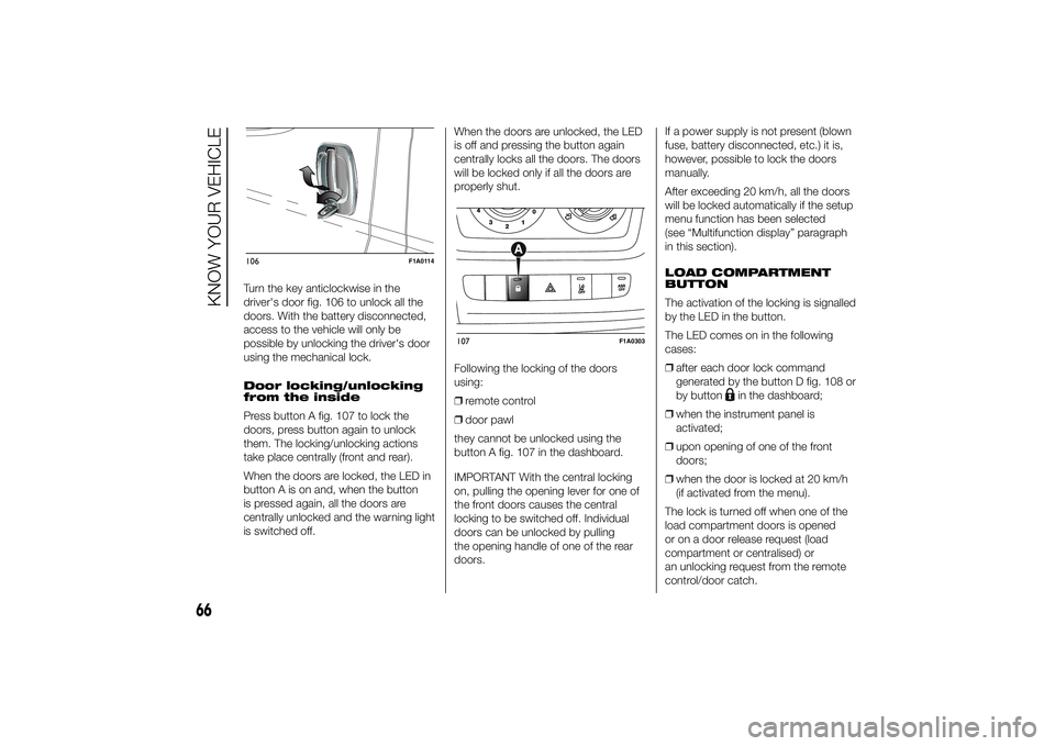
Turn the key anticlockwise in the
driver's door fig. 106 to unlock all the
doors. With the battery disconnected,
access to the vehicle will only be
possible by unlocking the driver's door
using the mechanical lock.
Door locking/unlocking
from the inside
Press button A fig. 107 to lock the
doors, press button again to unlock
them. The locking/unlocking actions
take place centrally (front and rear).
When the doors are locked, the LED in
button A is on and, when the button
is pressed again, all the doors are
centrally unlocked and the warning light
is switched off.When the doors are unlocked, the LED
is off and pressing the button again
centrally locks all the doors. The doors
will be locked only if all the doors are
properly shut.
Following the locking of the doors
using:
❒remote control
❒door pawl
they cannot be unlocked using the
button A fig. 107 in the dashboard.
IMPORTANT With the central locking
on, pulling the opening lever for one of
the front doors causes the central
locking to be switched off. Individual
doors can be unlocked by pulling
the opening handle of one of the rear
doors.If a power supply is not present (blown
fuse, battery disconnected, etc.) it is,
however, possible to lock the doors
manually.
After exceeding 20 km/h, all the doors
will be locked automatically if the setup
menu function has been selected
(see “Multifunction display” paragraph
in this section).
LOAD COMPARTMENT
BUTTON
The activation of the locking is signalled
by the LED in the button.
The LED comes on in the following
cases:
❒after each door lock command
generated by the button D fig. 108 or
by button
in the dashboard;
❒when the instrument panel is
activated;
❒upon opening of one of the front
doors;
❒when the door is locked at 20 km/h
(if activated from the menu).
The lock is turned off when one of the
load compartment doors is opened
or on a door release request (load
compartment or centralised) or
an unlocking request from the remote
control/door catch.
106
F1A0114
107
F1A0303
66
KNOW YOUR VEHICLE
Page 80 of 367
❒ASR
❒HBA
❒DST
❒ERM
54) 55) 56)
SYSTEM INTERVENTION
This is signalled by the flashing of
warning light
in the instrument panel,
to inform the driver that the vehicle is
in critical stability and grip conditions.
SYSTEM ACTIVATION
The ESC system switches on
automatically when the engine is
started and cannot be switched off.
HILL HOLDER SYSTEM
This system is an integral part of the
ESC system and facilitates starting on
slopes.
It is automatically activated in the
following conditions:
❒uphill: vehicle stationary on a road
with a gradient higher than 5%,
engine running, brake pressed and
gearbox in neutral or gear (other than
reverse) engaged;❒downhill: vehicle stationary on a road
with a gradient higher than 5%,
engine running, brake pressed and
reverse gear engaged.
When setting off, the ESC system
control unit maintains the braking
pressure on the wheels until the torque
necessary for starting is reached, or
in any case for a maximum of 2
seconds, allowing your right foot to be
moved easily from the brake pedal to
the accelerator.
When two seconds have elapsed,
without starting, the system is
automatically deactivated, gradually
releasing the braking pressure. During
this release stage, the typical brake
disengagement noise indicating that the
vehicle is going to move imminently
will be heard.
IMPORTANT The Hill Holder system is
not a parking brake; therefore, never
leave the vehicle without having
engaged the handbrake, turned the
engine off and engaged first gear,
so that it is parked in safe conditions
(for further information read the
"Parking" paragraph in the "Starting
and driving" chapter).ASR (AntiSlip
Regulation) SYSTEM
It is an integral part of the ESC system.
It automatically operates in the event
of one or both drive wheels slipping,
loss of grip on wet roads (aquaplaning)
and acceleration on slippery, snowy
or icy roads, etc.
Depending on the slipping conditions,
two different control systems are
activated:
❒if the slipping involves both drive
wheels, the ASR intervenes reducing
the power transmitted by the engine;
❒if the slipping only involves one of the
drive wheels, it intervenes
automatically braking the wheel that
is slipping.
58)
Engagement/ disengagement of the
ASR system
The ASR system switches on
automatically each time the engine is
started.
Whilst driving, the ASR can be switched
off and subsequently switched on
again by pressing the ASR OFF button
fig. 124.
57)
76
KNOW YOUR VEHICLE
Page 88 of 367
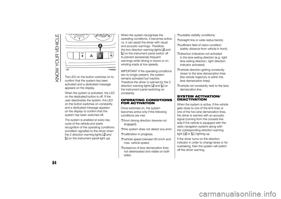
The LED on the button switches on to
confirm that the system has been
activated and a dedicated message
appears on the display.
When the system is activated, the LED
on the dedicated button is off. If the
user deactivates the system, the LED
on the button switches on constantly
and a dedicated message appears
on the display to confirm that the
system has been switched off.
The system is enabled at every key
cycle of the vehicle and starts
recognition of the operating conditions
(condition signalled to the driver when
the 2 direction warning lights
and
on the instrument panel light up).When the system recognises the
operating conditions, it becomes active,
i.e. it can assist the driver with visual
and acoustic warnings. Therefore
the two direction warning lights
and
on the instrument panel switch off
to prevent excessively frequent
warnings while driving in towns or on
winding roads at low speeds.
IMPORTANT If the operating conditions
are no longer present, the system
remains activated but inactive.
Therefore the driver is warned by the 2
direction warning lights
and
on
the instrument panel switching on
constantly.
OPERATING CONDITIONS
FOR ACTIVATION
Once switched on, the system
becomes active only if the following
conditions are met:
❒front driving direction (reverse not
engaged);
❒the system does not detect any error;
❒calibration in progress;
❒vehicle speed between 60 km/h and
max. vehicle speed;
❒presence of lane demarcation lines
not deteriorated and visible on both
sides;❒suitable visibility conditions;
❒straight line or wide radius bends;
❒sufficient field of vision condition
(safety distance from vehicle in front);
❒direction indicators not activated
in the lane exiting direction (e.g. right
lane exiting direction, right direction
indicator activated);
❒vehicle direction getting constantly
closer to the lane demarcation lines
(the vehicle trajectory is within the
lane demarcation lines);
❒vehicle not constantly next to the lane
demarcation line.
SYSTEM ACTIVATION/
DEACTIVATION
When the system is active, if the vehicle
gets close to one of the limit lines or
one of the two lane demarcation lines,
the driver is warned with an acoustic
signal (coming from the crossed line
side if the vehicle is equipped with the
radio navigation system) along with
the corresponding direction warning
light (
or
) lighting up.
If the driver turns on the direction
indicator in order to change lanes or for
overtaking, then the system will switch
off the driver warning.
127
F1A0322
84
KNOW YOUR VEHICLE
Page 120 of 367
If the set distance unit is "km", the
display enables setting of the fuel
consumption unit (km/l or l/100km).
If the set distance unit is "mi", the
display shows the amount of fuel
consumed in "mpg".
- press the
or
button to
select;
- if you enter the "Temperature"
submenu, pressing the MODE button
makes "°C" or "°F" appear on the
display (depending on the previous
setting);
- press the
or
button to
select;
When you have made the adjustment,
briefly press the MODE button to go
back to the submenu screen or hold
the button down to go back to the main
menu screen without storing.
- press the MODE button again to
return to the standard screen or to the
main menu according to where you
are in the menu.Selecting the language
(Language)
Display messages can be shown in
different languages: Italian, German,
English, Spanish, French, Portuguese
and Dutch.
To set the desired language, proceed
as follows:
- briefly press the MODE button: the
previously set "language" starts flashing
on the display;
- press the
or
button to
select;
- press the MODE button briefly to
return to the menu screen or hold the
button down to return to the standard
screen without storing.
Adjust the failure/
warning buzzer volume
(Buzzer Volume)
With this function the volume of the
acoustic signal which accompanies the
display of failure/warning can be
adjusted according to 8 levels.
To set the desired volume, proceed as
follows:
- briefly press the MODE button: the
previously set volume "level" will flash
on the display;- press the
or
button to
adjust;
- press the MODE button briefly to
return to the menu screen or hold the
button down to return to the standard
screen without storing.
Service
Scheduled servicing
Using this function you can display
information about the mileage intervals
for vehicle servicing.
To consult this information, proceed as
follows:
– briefly press the MODE button: the
display shows service requirements in
km or mi according to the previous
setting (see paragraph “Unit of
measure”);
– briefly press button MODE to go back
to the menu screen or press the button
for longer to go back to the standard
screen.
Oil change
This function displays information
regarding the remaining mileage before
the next oil change.
To consult this information, proceed as
follows:
116
KNOWING THE INSTRUMENT PANEL