key FIAT DUCATO BASE CAMPER 2015 Owner handbook (in English)
[x] Cancel search | Manufacturer: FIAT, Model Year: 2015, Model line: DUCATO BASE CAMPER, Model: FIAT DUCATO BASE CAMPER 2015Pages: 367, PDF Size: 19.73 MB
Page 67 of 367
FUEL CUT-OFF
SWITCH
The vehicle is fitted with a safety
switch that, in the event of a crash,
comes into operation by cutting
off the fuel supply and turning
off the engine as a consequence.When the inertia switch cuts in, it
cuts off the fuel supply and also
activates the hazard warning lights,
side lights and courtesy lights
while releasing all the doors and
displaying the relevant message;
they are deactivated by pressing
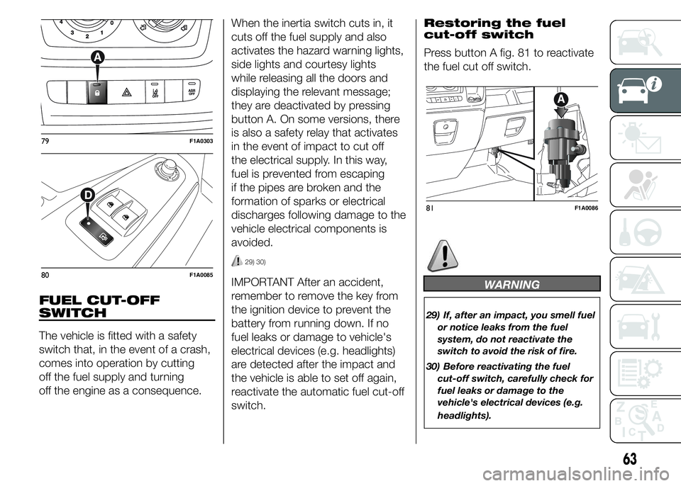
button A. On some versions, there
is also a safety relay that activates
in the event of impact to cut off
the electrical supply. In this way,
fuel is prevented from escaping
if the pipes are broken and the
formation of sparks or electrical
discharges following damage to the
vehicle electrical components is
avoided.
29) 30)
IMPORTANT After an accident,
remember to remove the key from
the ignition device to prevent the
battery from running down. If no
fuel leaks or damage to vehicle's
electrical devices (e.g. headlights)
are detected after the impact and
the vehicle is able to set off again,
reactivate the automatic fuel cut-off
switch.Restoring the fuel
cut-off switch
Press button A fig. 81 to reactivate
the fuel cut off switch.WARNING
29) If, after an impact, you smell fuel
or notice leaks from the fuel
system, do not reactivate the
switch to avoid the risk of fire.
30) Before reactivating the fuel
cut-off switch, carefully check for
fuel leaks or damage to the
vehicle's electrical devices (e.g.
headlights).
79F1A0303
80F1A0085
81F1A0086
63
Page 68 of 367
INTERIOR FITTINGS
UPPER STORAGE
COMPARTMENT -
REFRIGERATED
COMPARTMENT
(for versions/markets, where
provided)
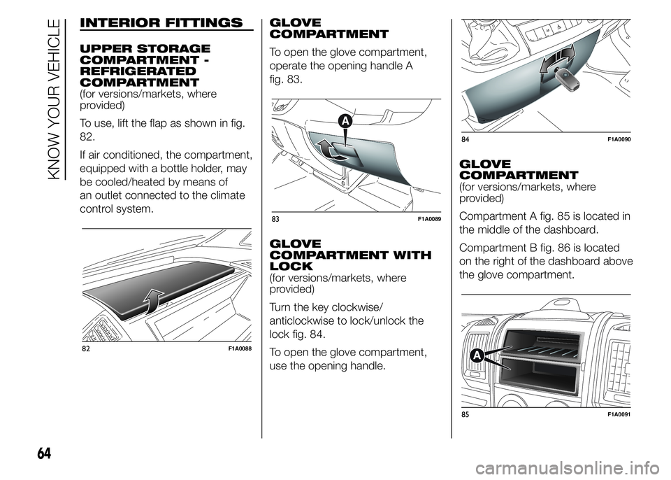
To use, lift the flap as shown in fig.
82.
If air conditioned, the compartment,
equipped with a bottle holder, may
be cooled/heated by means of
an outlet connected to the climate
control system.GLOVE
COMPARTMENT
To open the glove compartment,
operate the opening handle A
fig. 83.
GLOVE
COMPARTMENT WITH
LOCK
(for versions/markets, where
provided)
Turn the key clockwise/
anticlockwise to lock/unlock the
lock fig. 84.
To open the glove compartment,
use the opening handle.GLOVE
COMPARTMENT
(for versions/markets, where
provided)
Compartment A fig. 85 is located in
the middle of the dashboard.
Compartment B fig. 86 is located
on the right of the dashboard above
the glove compartment.
82F1A0088
83F1A0089
84F1A0090
85F1A0091
64
KNOW YOUR VEHICLE
Page 70 of 367
Certain outfits are equipped with a
protective grille on the window of
the partition inside the load
compartment.
CUP HOLDER - CAN
HOLDER
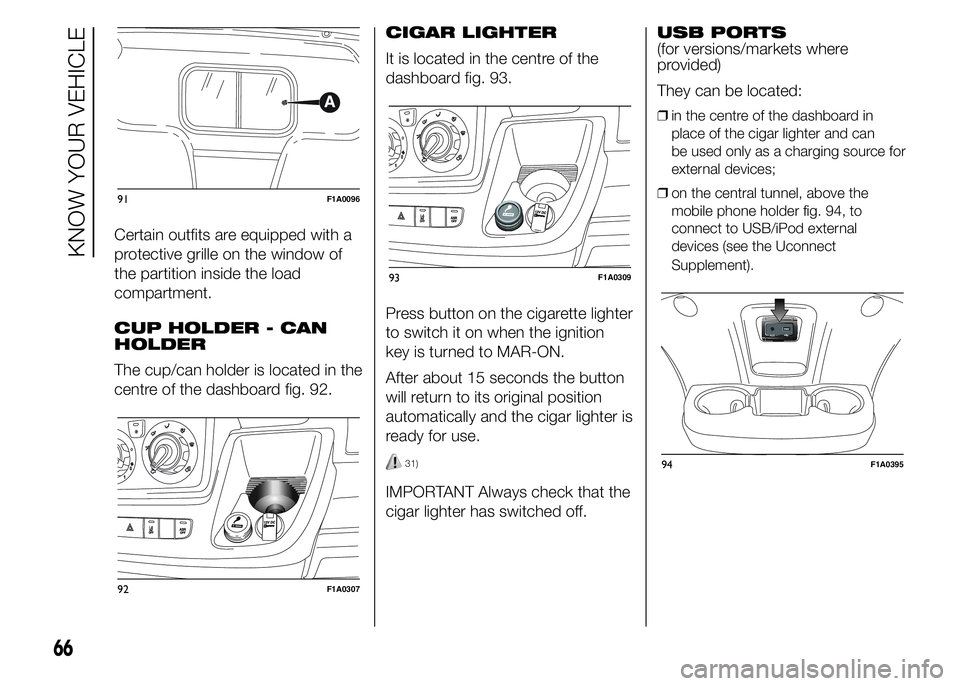
The cup/can holder is located in the
centre of the dashboard fig. 92.CIGAR LIGHTER
It is located in the centre of the
dashboard fig. 93.
Press button on the cigarette lighter
to switch it on when the ignition
key is turned to MAR-ON.
After about 15 seconds the button
will return to its original position
automatically and the cigar lighter is
ready for use.
31)
IMPORTANT Always check that the
cigar lighter has switched off.USB PORTS
(for versions/markets where
provided)
They can be located:
❒in the centre of the dashboard in
place of the cigar lighter and can
be used only as a charging source for
external devices;
❒on the central tunnel, above the
mobile phone holder fig. 94, to
connect to USB/iPod external
devices (see the Uconnect
Supplement).
91F1A0096
92F1A0307
93F1A0309
66
KNOW YOUR VEHICLE
94F1A0395
Page 76 of 367
DOORS
DOOR CENTRAL
LOCKING/UNLOCKING
Locking doors from
the outside
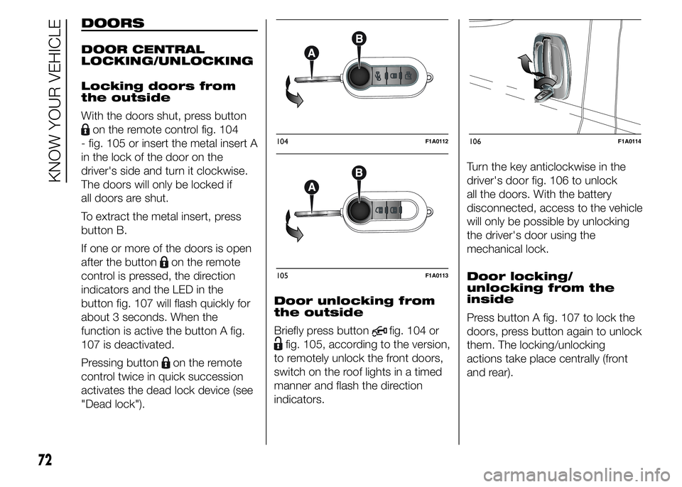
With the doors shut, press button
on the remote control fig. 104
- fig. 105 or insert the metal insert A
in the lock of the door on the
driver's side and turn it clockwise.
The doors will only be locked if
all doors are shut.
To extract the metal insert, press
button B.
If one or more of the doors is open
after the button
on the remote
control is pressed, the direction
indicators and the LED in the
button fig. 107 will flash quickly for
about 3 seconds. When the
function is active the button A fig.
107 is deactivated.
Pressing button
on the remote
control twice in quick succession
activates the dead lock device (see
"Dead lock").Door unlocking from
the outside
Briefly press button
fig. 104 or
fig. 105, according to the version,
to remotely unlock the front doors,
switch on the roof lights in a timed
manner and flash the direction
indicators.Turn the key anticlockwise in the
driver's door fig. 106 to unlock
all the doors. With the battery
disconnected, access to the vehicle
will only be possible by unlocking
the driver's door using the
mechanical lock.
Door locking/
unlocking from the
inside
Press button A fig. 107 to lock the
doors, press button again to unlock
them. The locking/unlocking
actions take place centrally (front
and rear).
104F1A0112
105F1A0113
106F1A0114
72
KNOW YOUR VEHICLE
Page 78 of 367
The dead lock device therefore
offers the best possible protection
against break-in attempts. We
recommend engaging it whenever
the vehicle is parked and left
unattended.
34)
Device activation
The dead lock device is
automatically activated on every
door with two short presses on the
button
on the key with remote
control fig. 104.
Device activation is indicated by 3
flashes of the direction indicators
and a flash of the LED on button A
fig. 107 on the dashboard.If one or more of the doors is not
perfectly shut, the dead lock device
will not be activated, thus
preventing a person getting into the
car through the open door and,
on shutting, it, remaining stuck
inside the passenger compartment.
Device deactivation
The system is disabled
automatically on every door in the
following cases:❒if the mechanical key is turned to the
opening position in the driver's door;
❒by unlocking the doors using the
remote control;
❒by turning the ignition key to the
MAR-ON position.
SLIDING SIDE DOOR
35) 36)
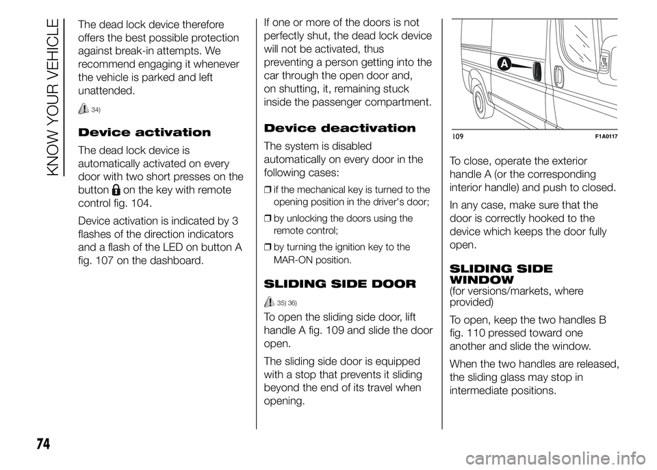
To open the sliding side door, lift
handle A fig. 109 and slide the door
open.
The sliding side door is equipped
with a stop that prevents it sliding
beyond the end of its travel when
opening.To close, operate the exterior
handle A (or the corresponding
interior handle) and push to closed.
In any case, make sure that the
door is correctly hooked to the
device which keeps the door fully
open.
SLIDING SIDE
WINDOW
(for versions/markets, where
provided)
To open, keep the two handles B
fig. 110 pressed toward one
another and slide the window.
When the two handles are released,
the sliding glass may stop in
intermediate positions.
109F1A0117
74
KNOW YOUR VEHICLE
Page 79 of 367
MOVING FOOTBOARD
(for versions/markets, where
provided)
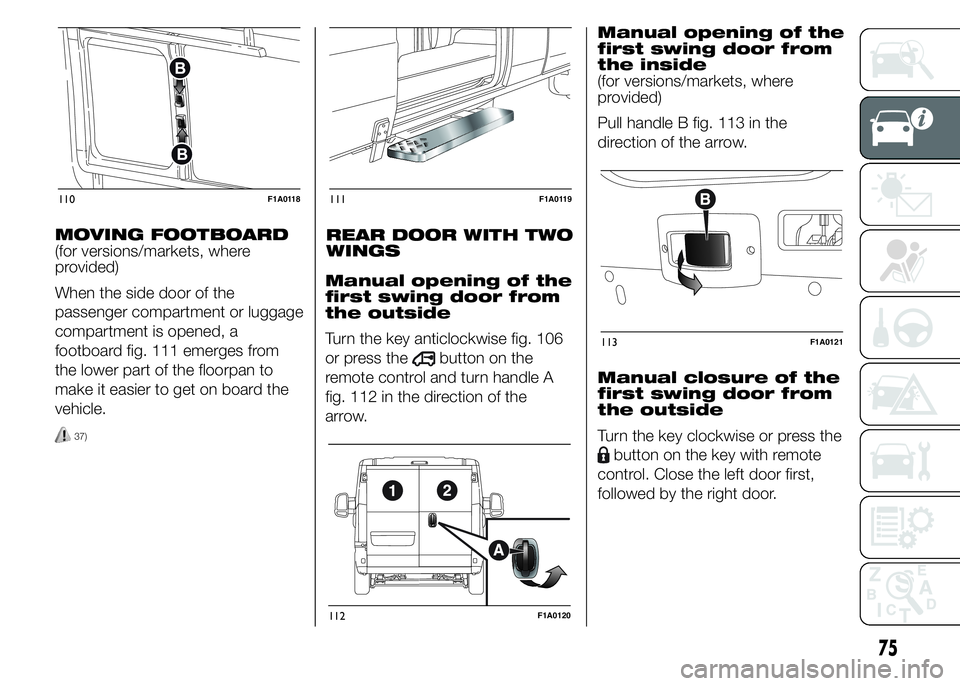
When the side door of the
passenger compartment or luggage
compartment is opened, a
footboard fig. 111 emerges from
the lower part of the floorpan to
make it easier to get on board the
vehicle.
37)
REAR DOOR WITH TWO
WINGS
Manual opening of the
first swing door from
the outside
Turn the key anticlockwise fig. 106
or press the
button on the
remote control and turn handle A
fig. 112 in the direction of the
arrow.Manual opening of the
first swing door from
the inside
(for versions/markets, where
provided)
Pull handle B fig. 113 in the
direction of the arrow.
Manual closure of the
first swing door from
the outside
Turn the key clockwise or press the
button on the key with remote
control. Close the left door first,
followed by the right door.
110F1A0118111F1A0119
112F1A0120
113F1A0121
75
Page 81 of 367
WARNING
34) Once the dead lock system is
engaged it is impossible to open
the doors from inside the vehicle.
Therefore, before engaging the
system check that there is no one
left inside. If the remote control
battery is flat, the system can be
disengaged only by inserting
the key metal insert in either of
the door locks as described
previously: in this case the device
remains active only for the rear
doors.
35) Before leaving the vehicle
parked with sliding doors open,
always check that the latch is
engaged.
36) Do not move the vehicle with
side doors open.37) Before setting off after parking
or before moving the vehicle in
any way, ensure that the
footboard is fully stowed away. As
the movement of the platform is
linked to that of the sliding side
door, thewarning light in the
instrument panel comes on if it is
not fully retracted in the same
way as when the rear doors are
not shut.
38) This spring loaded system has
activation forces that were
designed for optimum comfort.
Accidental knocks or a strong
gust of wind may release the
springs and close the doors
spontaneously.
39) With the doors opened to 180
degrees, no locking system is
effective. Do not use this opening
with the vehicle parked on a
gradient or when it is windy.
40) It is forbidden to drive the
vehicle with the footboard open.
41) Do not use the retracted
footboard for getting up or down
the load compartment.42) Make sure that the footboard is
suitably locked by the provided
retaining systems before, after
and during its use. An incomplete
opening or closing might cause
an improper movement of the
footboard with risks arising for the
operator and external users.
43) The footboard lightly projects
from the vehicle even if retracted;
therefore, when rear parking
sensors are provided, their
operating range is lightly reduced.
IMPORTANT
5) The footboard presence may
reduce the ramp approach angles;
it is therefore recommended, in
case of a very steep ramp, to
be very careful in order not to
damage the footboard.
77
Page 82 of 367
ELECTRIC WINDOWS
ELECTRIC
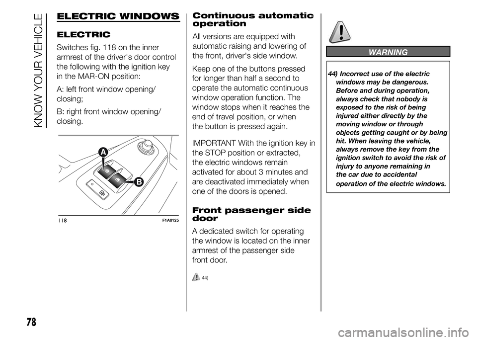
Switches fig. 118 on the inner
armrest of the driver's door control
the following with the ignition key
in the MAR-ON position:
A: left front window opening/
closing;
B: right front window opening/
closing.Continuous automatic
operation
All versions are equipped with
automatic raising and lowering of
the front, driver's side window.
Keep one of the buttons pressed
for longer than half a second to
operate the automatic continuous
window operation function. The
window stops when it reaches the
end of travel position, or when
the button is pressed again.
IMPORTANT With the ignition key in
the STOP position or extracted,
the electric windows remain
activated for about 3 minutes and
are deactivated immediately when
one of the doors is opened.
Front passenger side
door
A dedicated switch for operating
the window is located on the inner
armrest of the passenger side
front door.
44)
WARNING
44) Incorrect use of the electric
windows may be dangerous.
Before and during operation,
always check that nobody is
exposed to the risk of being
injured either directly by the
moving window or through
objects getting caught or by being
hit. When leaving the vehicle,
always remove the key from the
ignition switch to avoid the risk of
injury to anyone remaining in
the car due to accidental
operation of the electric windows.
118F1A0125
78
KNOW YOUR VEHICLE
Page 85 of 367
HEADLIGHTS
LIGHT BEAM
ALIGNMENT
The correct alignment of the
headlights is essential for the
comfort and safety of the driver and
other road users. To ensure the
best visibility when travelling with
the headlights on, the headlight
alignment must be correct. Contact
a Fiat Dealership to have the
headlights checked and adjusted.
HEADLIGHT
ALIGNMENT
CORRECTOR
This device works with the ignition
key in the MAR-ON position and
the dipped beam headlights on.
The vehicle tilts backwards when it
is laden, raising the beam.
The beams must therefore be
realigned in this case.Headlight alignment
adjustment
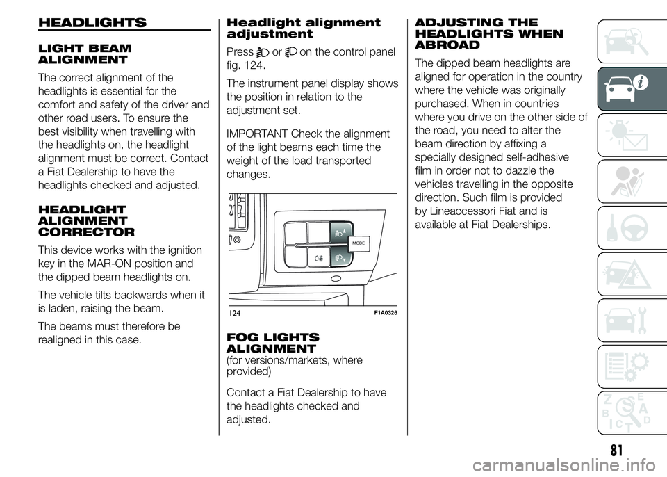
Pressoron the control panel
fig. 124.
The instrument panel display shows
the position in relation to the
adjustment set.
IMPORTANT Check the alignment
of the light beams each time the
weight of the load transported
changes.
FOG LIGHTS
ALIGNMENT
(for versions/markets, where
provided)
Contact a Fiat Dealership to have
the headlights checked and
adjusted.ADJUSTING THE
HEADLIGHTS WHEN
ABROAD
The dipped beam headlights are
aligned for operation in the country
where the vehicle was originally
purchased. When in countries
where you drive on the other side of
the road, you need to alter the
beam direction by affixing a
specially designed self-adhesive
film in order not to dazzle the
vehicles travelling in the opposite
direction. Such film is provided
by Lineaccessori Fiat and is
available at Fiat Dealerships.
MODEMODE
124F1A0326
81
Page 90 of 367
HILL DESCENT
CONTROL (HDC)
SYSTEM
It is an integral part of the ESC and
is aimed at keeping the vehicle at
a constant speed during a descent,
operating autonomously on the
brakes in various ways at the same
time. In this way the vehicle stability
and completely safe driving are
guaranteed, above all in poor grip
conditions and/or steep descents.
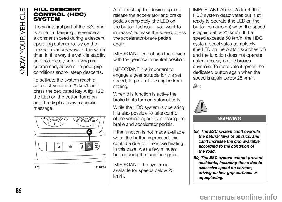
To activate the system reach a
speed slower than 25 km/h and
press the dedicated key A fig. 126;
the LED on the button turns on
and the display gives a specific
message.After reaching the desired speed,
release the accelerator and brake
pedals completely (the LED on
the button flashes). If you want to
increase/decrease the speed, press
the accelerator/brake pedals
again.
IMPORTANT Do not use the device
with the gearbox in neutral position.
IMPORTANT It is important to
engage a gear suitable for the set
speed, to prevent the engine from
stalling.
When this function is active the
brake lights turn on automatically.
While the HDC system is operating
it is also possible to take control
of the vehicle again by pressing the
brake and accelerator pedals.
If the function is not made available
when the button is pressed, this
could be due to brake overheating.
In this case, wait a few minutes
before using the function again.
IMPORTANT The system is
available for speeds below 25
km/h.IMPORTANT Above 25 km/h the
HDC system deactivates but is still
ready to operate (the LED on the
button remains on) when the speed
is again below 25 km/h. If the
speed exceeds 50 km/h, the HDC
system deactivates completely
(the LED on the button switches off)
and the function does not operate
autonomously on the brakes
anymore. To reactivate it, press the
dedicated button again when the
speed is again below 25 km/h.
8)
WARNING
58) The ESC system can’t overrule
the natural laws of physics, and
can’t increase the grip available
according to the condition of
the road.
59) The ESC system cannot prevent
accidents, including those due to
excessive speed on corners,
driving on low-grip surfaces or
aquaplaning.
126F1A0300
86
KNOW YOUR VEHICLE