lock FIAT DUCATO BASE CAMPER 2015 Owner handbook (in English)
[x] Cancel search | Manufacturer: FIAT, Model Year: 2015, Model line: DUCATO BASE CAMPER, Model: FIAT DUCATO BASE CAMPER 2015Pages: 367, PDF Size: 19.73 MB
Page 66 of 367
BATTERY
DISCONNECTION
FUNCTION
(DISCONNECTOR)
(for versions/markets, where
provided)
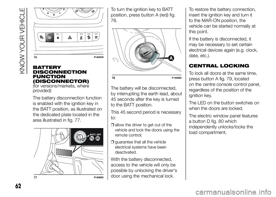
The battery disconnection function
is enabled with the ignition key in
the BATT position, as illustrated on
the dedicated plate located in the
area illustrated in fig. 77.To turn the ignition key to BATT
position, press button A (red) fig.
78.
The battery will be disconnected,
by interrupting the earth lead, about
45 seconds after the key is turned
to the BATT position.
This 45 second period is necessary
to:
❒allow the driver to get out of the
vehicle and lock the doors using the
remote control;
❒guarantee that all the vehicle
electrical systems have been
deactivated.
With the battery disconnected,
access to the vehicle will only be
possible by unlocking the driver's
door using the mechanical lock.To restore the battery connection,
insert the ignition key and turn it
to the MAR-ON position, the
vehicle can be started normally at
this point.
If the battery is disconnected, it
may be necessary to set certain
electrical devices again (e.g. clock,
date, etc.).
CENTRAL LOCKING
To lock all doors at the same time,
press button A fig. 79, located
on the centre console control panel,
regardless of the position of the
ignition key.
The LED on the button switches on
when the doors are locked.
The electric window panel features
a button D fig. 80 which
independently unlocks/locks the
load compartment.
76F1A0330
77F1A0082
78F1A0083
62
KNOW YOUR VEHICLE
Page 68 of 367
INTERIOR FITTINGS
UPPER STORAGE
COMPARTMENT -
REFRIGERATED
COMPARTMENT
(for versions/markets, where
provided)
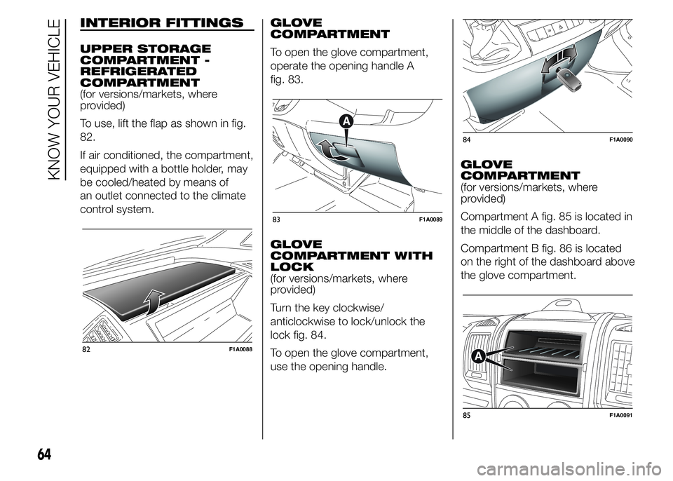
To use, lift the flap as shown in fig.
82.
If air conditioned, the compartment,
equipped with a bottle holder, may
be cooled/heated by means of
an outlet connected to the climate
control system.GLOVE
COMPARTMENT
To open the glove compartment,
operate the opening handle A
fig. 83.
GLOVE
COMPARTMENT WITH
LOCK
(for versions/markets, where
provided)
Turn the key clockwise/
anticlockwise to lock/unlock the
lock fig. 84.
To open the glove compartment,
use the opening handle.GLOVE
COMPARTMENT
(for versions/markets, where
provided)
Compartment A fig. 85 is located in
the middle of the dashboard.
Compartment B fig. 86 is located
on the right of the dashboard above
the glove compartment.
82F1A0088
83F1A0089
84F1A0090
85F1A0091
64
KNOW YOUR VEHICLE
Page 69 of 367
CUP HOLDER - CAN
HOLDER - BOTTLE
HOLDER ON
DASHBOARD
(for versions/markets, where
provided)
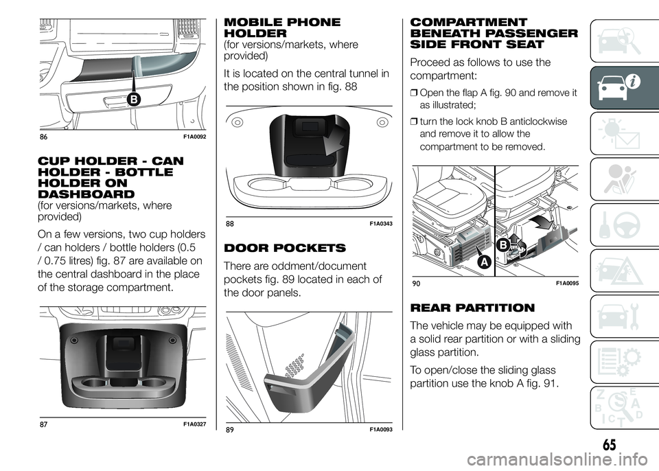
On a few versions, two cup holders
/ can holders / bottle holders (0.5
/ 0.75 litres) fig. 87 are available on
the central dashboard in the place
of the storage compartment.MOBILE PHONE
HOLDER
(for versions/markets, where
provided)
It is located on the central tunnel in
the position shown in fig. 88
DOOR POCKETS
There are oddment/document
pockets fig. 89 located in each of
the door panels.COMPARTMENT
BENEATH PASSENGER
SIDE FRONT SEAT
Proceed as follows to use the
compartment:
❒Open the flap A fig. 90 and remove it
as illustrated;
❒turn the lock knob B anticlockwise
and remove it to allow the
compartment to be removed.
REAR PARTITION
The vehicle may be equipped with
a solid rear partition or with a sliding
glass partition.
To open/close the sliding glass
partition use the knob A fig. 91.
86F1A0092
87F1A0327
88F1A0343
89F1A0093
90F1A0095
65
Page 72 of 367
TABLET HOLDER
(for versions/markets, where
provided)
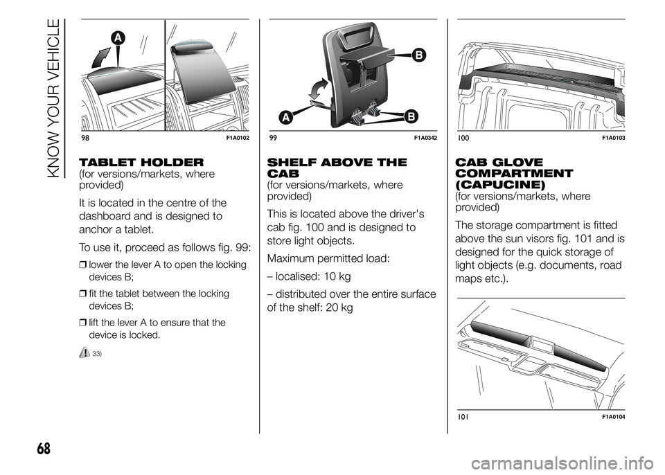
It is located in the centre of the
dashboard and is designed to
anchor a tablet.
To use it, proceed as follows fig. 99:
❒lower the lever A to open the locking
devices B;
❒fit the tablet between the locking
devices B;
❒lift the lever A to ensure that the
device is locked.
33)
SHELF ABOVE THE
CAB
(for versions/markets, where
provided)
This is located above the driver's
cab fig. 100 and is designed to
store light objects.
Maximum permitted load:
– localised: 10 kg
– distributed over the entire surface
of the shelf: 20 kgCAB GLOVE
COMPARTMENT
(CAPUCINE)
(for versions/markets, where
provided)
The storage compartment is fitted
above the sun visors fig. 101 and is
designed for the quick storage of
light objects (e.g. documents, road
maps etc.).
98F1A010299F1A0342100F1A0103
101F1A0104
68
KNOW YOUR VEHICLE
Page 74 of 367
The tachograph is installed and
sealed by authorised personnel: do
not try and access the device or
the supply and recording leads
in any way. It is the responsibility of
the owner of the vehicle on which
the tachograph is installed to check
the device regularly.
The check must be carried out at
least every two years and a test
must be carried out to ensure that it
is working properly. Ensure that
the data label is renewed after
every check and that the
label contains the specified data.SPEED BLOCK
(for versions/markets, where
provided)
The vehicle is equipped with a
speed limitation function that can
be set at the user's request to one
of 4 predefined values: 90, 100,
110, 130 km/h.
To activate/deactivate this function,
contact a Fiat Dealership.
Following the operation, a sticker
will be applied to the windscreen
showing the maximum speed
setting.
IMPORTANT The speedometer
could indicate a higher maximum
speed than the effective one, set by
the Dealership, in accordance with
the regulations in force.
SELF-LEVELLING AIR
SUSPENSION
GENERAL
INFORMATION
The system only acts on the rear
wheels.
The system maintains the rear ride
setting for the vehicle constant in
any loading condition, while
ensuring a greater driving comfort.
In addition, the system allows
the height of the vehicle to
be adjusted with the vehicle
stationary, by selecting from 7
different positions to facilitate
access to the rear compartment.
HEIGHT ADJUSTMENT
There are 7 pre-defined levels for
the free height from the ground:
from “ride -3” to “ride 0” till “ride
+3”.
The multifunction display, located in
the middle of the instrument panel,
can show the ride position.
70
KNOW YOUR VEHICLE
Page 76 of 367
DOORS
DOOR CENTRAL
LOCKING/UNLOCKING
Locking doors from
the outside
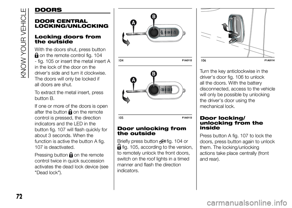
With the doors shut, press button
on the remote control fig. 104
- fig. 105 or insert the metal insert A
in the lock of the door on the
driver's side and turn it clockwise.
The doors will only be locked if
all doors are shut.
To extract the metal insert, press
button B.
If one or more of the doors is open
after the button
on the remote
control is pressed, the direction
indicators and the LED in the
button fig. 107 will flash quickly for
about 3 seconds. When the
function is active the button A fig.
107 is deactivated.
Pressing button
on the remote
control twice in quick succession
activates the dead lock device (see
"Dead lock").Door unlocking from
the outside
Briefly press button
fig. 104 or
fig. 105, according to the version,
to remotely unlock the front doors,
switch on the roof lights in a timed
manner and flash the direction
indicators.Turn the key anticlockwise in the
driver's door fig. 106 to unlock
all the doors. With the battery
disconnected, access to the vehicle
will only be possible by unlocking
the driver's door using the
mechanical lock.
Door locking/
unlocking from the
inside
Press button A fig. 107 to lock the
doors, press button again to unlock
them. The locking/unlocking
actions take place centrally (front
and rear).
104F1A0112
105F1A0113
106F1A0114
72
KNOW YOUR VEHICLE
Page 77 of 367
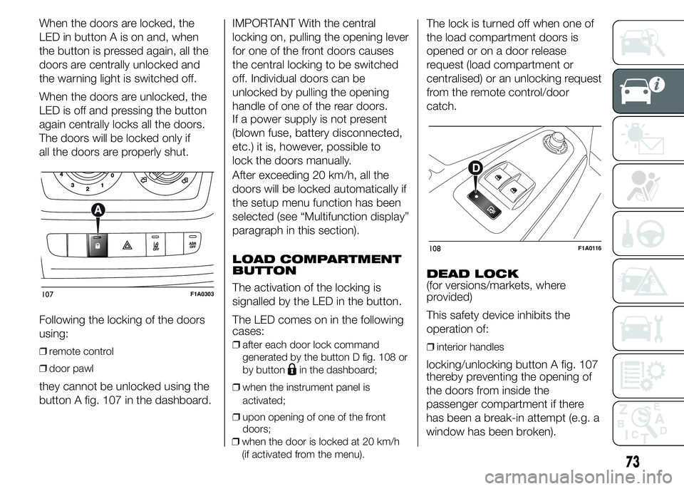
When the doors are locked, the
LED in button A is on and, when
the button is pressed again, all the
doors are centrally unlocked and
the warning light is switched off.
When the doors are unlocked, the
LED is off and pressing the button
again centrally locks all the doors.
The doors will be locked only if
all the doors are properly shut.
Following the locking of the doors
using:
❒remote control
❒door pawl
they cannot be unlocked using the
button A fig. 107 in the dashboard.IMPORTANT With the central
locking on, pulling the opening lever
for one of the front doors causes
the central locking to be switched
off. Individual doors can be
unlocked by pulling the opening
handle of one of the rear doors.
If a power supply is not present
(blown fuse, battery disconnected,
etc.) it is, however, possible to
lock the doors manually.
After exceeding 20 km/h, all the
doors will be locked automatically if
the setup menu function has been
selected (see “Multifunction display”
paragraph in this section).
LOAD COMPARTMENT
BUTTON
The activation of the locking is
signalled by the LED in the button.
The LED comes on in the following
cases:
❒after each door lock command
generated by the button D fig. 108 or
by button
in the dashboard;
❒when the instrument panel is
activated;
❒upon opening of one of the front
doors;
❒when the door is locked at 20 km/h
(if activated from the menu).
The lock is turned off when one of
the load compartment doors is
opened or on a door release
request (load compartment or
centralised) or an unlocking request
from the remote control/door
catch.
DEAD LOCK
(for versions/markets, where
provided)
This safety device inhibits the
operation of:
❒interior handles
locking/unlocking button A fig. 107
107F1A0303
108F1A0116
73
thereby preventing the opening of
the doors from inside the
passenger compartment if there
has been a break-in attempt (e.g. a
window has been broken).
Page 78 of 367
The dead lock device therefore
offers the best possible protection
against break-in attempts. We
recommend engaging it whenever
the vehicle is parked and left
unattended.
34)
Device activation
The dead lock device is
automatically activated on every
door with two short presses on the
button
on the key with remote
control fig. 104.
Device activation is indicated by 3
flashes of the direction indicators
and a flash of the LED on button A
fig. 107 on the dashboard.If one or more of the doors is not
perfectly shut, the dead lock device
will not be activated, thus
preventing a person getting into the
car through the open door and,
on shutting, it, remaining stuck
inside the passenger compartment.
Device deactivation
The system is disabled
automatically on every door in the
following cases:❒if the mechanical key is turned to the
opening position in the driver's door;
❒by unlocking the doors using the
remote control;
❒by turning the ignition key to the
MAR-ON position.
SLIDING SIDE DOOR
35) 36)
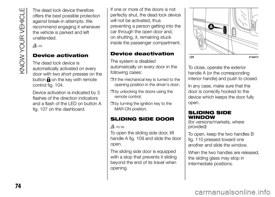
To open the sliding side door, lift
handle A fig. 109 and slide the door
open.
The sliding side door is equipped
with a stop that prevents it sliding
beyond the end of its travel when
opening.To close, operate the exterior
handle A (or the corresponding
interior handle) and push to closed.
In any case, make sure that the
door is correctly hooked to the
device which keeps the door fully
open.
SLIDING SIDE
WINDOW
(for versions/markets, where
provided)
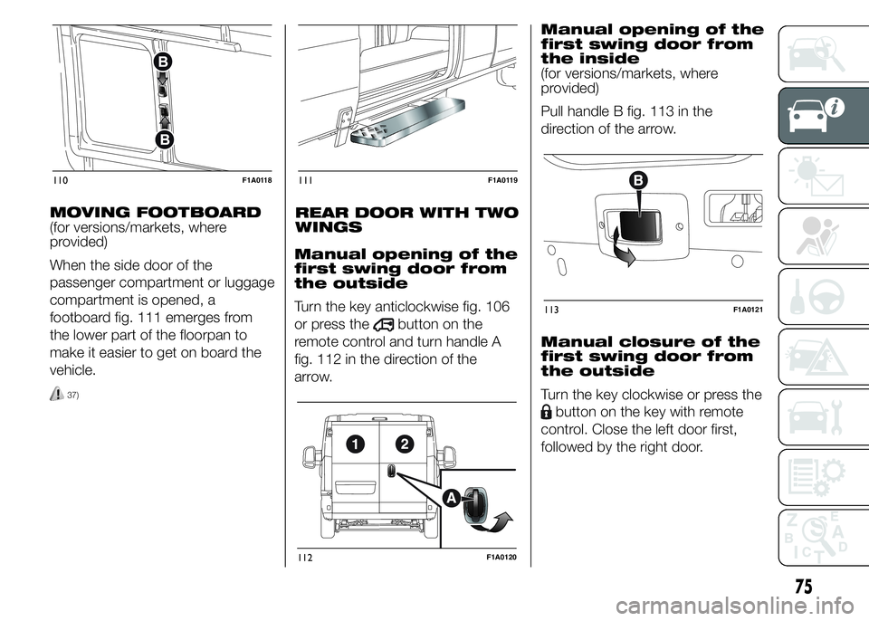
To open, keep the two handles B
fig. 110 pressed toward one
another and slide the window.
When the two handles are released,
the sliding glass may stop in
intermediate positions.
109F1A0117
74
KNOW YOUR VEHICLE
Page 79 of 367
MOVING FOOTBOARD
(for versions/markets, where
provided)
When the side door of the
passenger compartment or luggage
compartment is opened, a
footboard fig. 111 emerges from
the lower part of the floorpan to
make it easier to get on board the
vehicle.
37)
REAR DOOR WITH TWO
WINGS
Manual opening of the
first swing door from
the outside
Turn the key anticlockwise fig. 106
or press the
button on the
remote control and turn handle A
fig. 112 in the direction of the
arrow.Manual opening of the
first swing door from
the inside
(for versions/markets, where
provided)
Pull handle B fig. 113 in the
direction of the arrow.
Manual closure of the
first swing door from
the outside
Turn the key clockwise or press the
button on the key with remote
control. Close the left door first,
followed by the right door.
110F1A0118111F1A0119
112F1A0120
113F1A0121
75
Page 80 of 367
Manual opening of the
second swing door
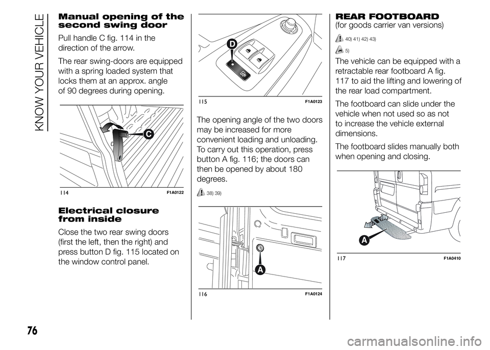
Pull handle C fig. 114 in the
direction of the arrow.
The rear swing-doors are equipped
with a spring loaded system that
locks them at an approx. angle
of 90 degrees during opening.
Electrical closure
from inside
Close the two rear swing doors
(first the left, then the right) and
press button D fig. 115 located on
the window control panel.The opening angle of the two doors
may be increased for more
convenient loading and unloading.
To carry out this operation, press
button A fig. 116; the doors can
then be opened by about 180
degrees.
38) 39)
REAR FOOTBOARD
(for goods carrier van versions)
40) 41) 42) 43)
5)
The vehicle can be equipped with a
retractable rear footboard A fig.
117 to aid the lifting and lowering of
the rear load compartment.
The footboard can slide under the
vehicle when not used so as not
to increase the vehicle external
dimensions.
The footboard slides manually both
when opening and closing.
114F1A0122
115F1A0123
116F1A0124
117F1A0410
76
KNOW YOUR VEHICLE