stop start FIAT DUCATO BASE CAMPER 2015 Owner handbook (in English)
[x] Cancel search | Manufacturer: FIAT, Model Year: 2015, Model line: DUCATO BASE CAMPER, Model: FIAT DUCATO BASE CAMPER 2015Pages: 367, PDF Size: 19.73 MB
Page 185 of 367
29) If thewarning light flashes
for about 60 seconds after
starting or during prolonged
cranking, this indicates a fault in
the glow plug preheating system.
Use the vehicle normally if the
engine starts, but contact a Fiat
Dealership as soon as possible.
30) Remember that the brake servo
and power steering are not
operational until the engine has
been started, so you need to apply
much more force than usual to
the brake pedal and steering
wheel.
31) Never start the engine by
pushing, towing or driving
downhill. This could cause fuel to
flow into the catalytic converter
and damage it beyond repair.
32) A quick burst on the accelerator
before turning off the engine
serves absolutely no practical
purpose; it wastes fuel and is
especially damaging to
turbocharged engines.
33) In some cases, when the engine
switches off, the fan could
activate for max. 120 seconds.
WARNING
129) It is dangerous to run the
engine in enclosed areas. The
engine takes in oxygen and
releases carbon dioxide, carbon
monoxide and other toxic gases.
PARKING
Proceed as follows:
❒stop the engine and engage the
handbrake;
❒engage a gear (on a slope, engage
first gear if the car is facing uphill or
reverse if it is facing downhill) and
leave the wheels steered.
If the vehicle is parked on a steep
slope, it is advisable to block the
wheels with a wedge or stone.
Do not leave the key in the ignition
as this drains the battery. Always
remove the key when you leave the
car.
130)
HANDBRAKE
The handbrake lever is located to
the left of the driver's seat fig. 171.
Pull the lever upwards to engage
the handbrake and ensure that the
vehicle does not move.
IMPORTANT Make sure that the
handbrake is engaged in such
a way as to ensure the stationing of
the vehicle, especially in the case
of steep slopes and full load.
181
Page 188 of 367
LOADING ADVICE
The Fiat Ducato version used by
you has been designed and type
approved on the basis of certain
maximum weights (see "Weights"
table in the "Technical Data"
chapter): kerb weight, payload,
total weight, maximum weight on
front axle, maximum weight on rear
axle, towable weight.
IMPORTANT The maximum
permitted load on the floor
fastenings is 500 kg; the maximum
permitted load on the side panel
is 150 kg.
IMPORTANT For versions with right
and left side flaps, it is advisable
to reposition the release lever in the
closed position before lowering
the sides.
36)
132) 133) 134)
In addition to these general
precautions, some simple
precautions can improve driving
safety, travelling comfort and
vehicle durability:
❒distribute the load evenly over the
platform: if it is necessary to
concentrate it in a single area,
choose an area mid-way between
both axles;
❒lastly, remember that the vehicle’s
dynamic behaviour is affected by
the weight transported: in particular,
the stopping distances are longer,
especially at high speed.
IMPORTANT
36) Each of these must be strictly
observed and MUST NEVER BE
EXCEEDED in any case. In
particular, ensure that you never
exceed the maximum permitted
weights on the front and rear
axles when arranging the load on
the vehicle (particularly if the
vehicle is equipped with a specific
trim level).
WARNING
132) Irregular trajectories and abrupt
braking may cause sudden
movements of the load with
consequent situations of hazard
for the driver and passengers:
before setting off, secure the load
tightly using the appropriate
hooks on the floor and use steel
cables, ropes or chains strong
enough to hold the items to be
secured.
133) If a vehicle is parked on a very
steep gradient or with a side
gradient, opening the rear door or
side door could cause any
unsecured items to emerge
suddenly.
134) If you wish to carry a reserve of
petrol in a can, observe the legal
restrictions and only use a can
that is type-approved and
properly secured to the load
anchorage eyebolts. Anyway, by
doing so, you increase the risk
of fire in the event of an accident
with your vehicle.
184
STARTING AND DRIVING
Page 190 of 367
Unnecessary actions
Avoid accelerating when stopped at
traffic lights or before switching off
the engine. This action and also
double declutching is absolutely
pointless on modern cars and also
increases consumption and
pollution.
Gear selection
As soon as the conditions of the
traffic and road permit, use a higher
gear. Using a low gear for faster
acceleration will increase
consumption.
In the same way improper use of a
high gear increases consumption,
emissions and engine wear.
Max. speed
Fuel consumption increases
considerably with speed. Maintain a
constant speed, avoiding
unnecessary braking and
acceleration, which cost in terms of
both fuel consumption and
emissions.Acceleration
Accelerating violently will greatly
affect consumption and emissions:
acceleration should be gradual.
USAGE CONDITIONS
The main usage conditions that
negatively affect fuel consumption
are listed below.
Cold starting
Short journeys and frequent cold
starts do not allow the engine
to reach optimum operating
temperature.
This results in a significant increase
in consumption levels (from +15
to +30% on the urban cycle) and
emissions.Traffic and road
conditions
Rather high consumption levels are
linked to situations with heavy
traffic, for instance when travelling
in queues with frequent use of
the lower gears or in cities with
many traffic lights. Winding
mountain roads and rough road
surfaces also adversely affect
consumption.
Stops in traffic
During prolonged hold-ups (e.g.
level crossings) the engine should
be switched off.
186
STARTING AND DRIVING
Page 196 of 367
INSTRUCTIONS FOR
USING THE
REMOVABLE BALL
HEAD TOW BAR
37) 38) 39) 40) 41) 42)
Before setting off, check the correct
locking of the removable ball head
tow bar, as follows:
❒The green mark of the flywheel must
coincide with the green mark on the
tow bar.
❒The flywheel is in the stop position on
the tow bar (without slot).
❒Locked lock and key removed. The
flywheel cannot be removed.
❒Ball head bar firmly secured to the
housing pipe. Check by shaking
with a hand.
The fitting procedure must be
repeated if any of the 4 checked
requirements is not met.
If even only one of the requirements
is not met the tow hook must not
be used, as in this case there is risk
of accidents. Contact the joint
manufacturer.
The ball head tow bar can be fitted
and removed manually, without
needing any tool.Never use working tools or means,
as the mechanism could be
damaged.
Never unlock in the case of trailer
attached to the vehicle or fitted
rack.
When driving without trailer or rack
the ball head tow bar must be
removed and the closing plug must
always be inserted in the housing
pipe. This applies particularly if
the visibility of the number plate
characters or of the lighting system
is reduced.
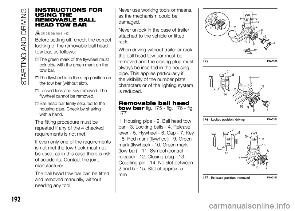
Removable ball head
tow barfig. 175 - fig. 176 - fig.
177
1. Housing pipe - 2. Ball head tow
bar - 3. Locking balls - 4. Release
lever - 5. Flywheel - 6. Cap - 7. Key
- 8. Red mark (flywheel) - 9. Green
mark (flywheel) - 10. Green mark
(tow bar) - 11. Symbol (control
release) - 12. Closing plug - 13.
Coupling pin - 14. No slot between
2 and 5 - 15. Slot of approx. 5
mm
175F1A0380
176 - Locked position, drivingF1A0381
177 - Released position, removedF1A0382
192
STARTING AND DRIVING
Page 200 of 367
IMPORTANT
43) Keep your speed down when
snow chains are fitted; do not
exceed 50 km/h. Avoid potholes,
steps and pavements and avoid
driving for long distances on
roads not covered with snow to
prevent damaging the vehicle and
the roadbed.
PROLONGED
VEHICLE INACTIVITY
If the vehicle needs to be off the
road for longer than one month, the
following precautions must be
taken:
❒park the vehicle indoors in a dry and,
if possible, well-ventilated place;
❒engage a gear;
❒check that the handbrake is not
engaged;
❒disconnect the negative battery
terminal; if the vehicle is equipped
with a battery disconnection function
(disconnector), see the description
of the procedure in the "Controls"
paragraph in the "Dashboard and
controls" section;
❒clean and protect the painted parts
using protective wax;
❒clean and protect the shiny metal
parts using special compounds
available commercially;
❒sprinkle talcum powder on the
windscreen and rear window wiper
rubber blades and lift them off the
glass;
❒slightly open the windows;❒cover the vehicle with a piece of
fabric or perforated plastic sheet. Do
not use compact plastic tarpaulins,
which prevent humidity from
evaporating from the surface of the
vehicle;
❒inflate tyres to +0.5 bar above the
standard specified pressure and
check it at intervals;
❒do not drain the engine cooling
system.
IMPORTANT If the vehicle is
equipped with an alarm system,
switch off the vehicle alarm with the
remote control.
IMPORTANT After turning the
ignition key to STOP and having
closed the driver side door, wait at
least one minute before
disconnecting the electrical supply
from the battery. When
reconnecting the electrical supply
to the battery, make sure that
the ignition key is in the STOP
position and the driver side door is
closed.
196
STARTING AND DRIVING
Page 210 of 367
❒after having driven for about 10
minutes, stop and recheck the tyre
pressure; remember to apply the
handbrake;
❒if a pressure value of at least 3 bar is
detected, restore the correct
pressure prescribed in the paragraph
“Inflation pressure” in “Technical
specification” (with the engine
running and the handbrake
engaged), resume driving and drive
with care to nearest Fiat Dealership.
FOR CHECKING AND
RESTORING
PRESSURE ONLY
The compressor can also be used
solely for restoring pressure.
❒Pull the handbrake.
❒Undo the cap for the tyre valve,
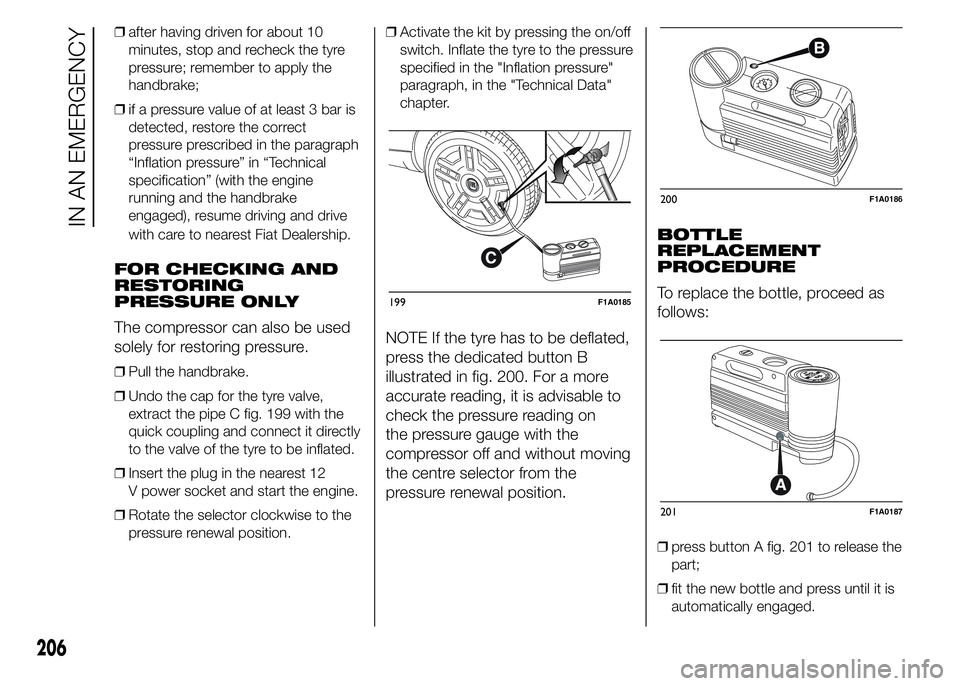
extract the pipe C fig. 199 with the
quick coupling and connect it directly
to the valve of the tyre to be inflated.
❒Insert the plug in the nearest 12
V power socket and start the engine.
❒Rotate the selector clockwise to the
pressure renewal position.❒Activate the kit by pressing the on/off
switch. Inflate the tyre to the pressure
specified in the "Inflation pressure"
paragraph, in the "Technical Data"
chapter.
NOTE If the tyre has to be deflated,
press the dedicated button B
illustrated in fig. 200. For a more
accurate reading, it is advisable to
check the pressure reading on
the pressure gauge with the
compressor off and without moving
the centre selector from the
pressure renewal position.BOTTLE
REPLACEMENT
PROCEDURE
To replace the bottle, proceed as
follows:
❒press button A fig. 201 to release the
part;
❒fit the new bottle and press until it is
automatically engaged.
199F1A0185
200F1A0186
201F1A0187
206
IN AN EMERGENCY
Page 225 of 367
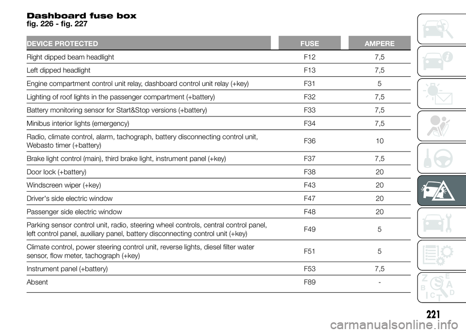
Dashboard fuse box
fig. 226 - fig. 227
DEVICE PROTECTED FUSE AMPERE
Right dipped beam headlight F12 7,5
Left dipped headlight F13 7,5
Engine compartment control unit relay, dashboard control unit relay (+key) F31 5
Lighting of roof lights in the passenger compartment (+battery) F32 7,5
Battery monitoring sensor for Start&Stop versions (+battery) F33 7,5
Minibus interior lights (emergency) F34 7,5
Radio, climate control, alarm, tachograph, battery disconnecting control unit,
Webasto timer (+battery)F36 10
Brake light control (main), third brake light, instrument panel (+key) F37 7,5
Door lock (+battery) F38 20
Windscreen wiper (+key) F43 20
Driver's side electric window F47 20
Passenger side electric window F48 20
Parking sensor control unit, radio, steering wheel controls, central control panel,
left control panel, auxiliary panel, battery disconnecting control unit (+key)F49 5
Climate control, power steering control unit, reverse lights, diesel filter water
sensor, flow meter, tachograph (+key)F51 5
Instrument panel (+battery) F53 7,5
AbsentF89 -
221
Page 229 of 367
BATTERY
RECHARGING
IMPORTANT The battery
recharging procedure is given as
information only. You are advised to
contact a Fiat Dealership to have
this operation carried out.
IMPORTANT After turning the
ignition key to STOP and having
closed the driver side door, wait at
least one minute before
disconnecting the electrical supply
from the battery. When
reconnecting the electrical supply
to the battery, make sure that
the ignition key is in the STOP
position and the driver side door is
closed.
Charging should be slow at a low
ampere rating for approximately 24
hours. Charging for a longer time
may damage the battery.
169) 170)
IN THE ABSENCE OF
START&STOP SYSTEM
To recharge, proceed as follows:
❒disconnect the negative battery
terminal;
❒connect the charger cables to the
battery terminals, observing the
polarity;
❒turn on the charger;
❒when it is recharged, turn the charger
off before disconnecting it from the
battery;
❒reconnect the negative battery
terminal.
WITH START&STOP
SYSTEM
To recharge, proceed as follows:
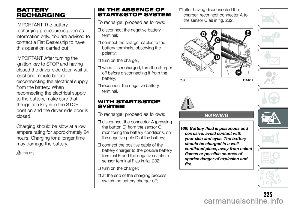
❒disconnect the connector A (pressing
the button B) from the sensor C
monitoring the battery conditions, on
the negative pole D of the battery;
❒connect the positive cable of the
battery charger to the positive battery
terminal E and the negative cable to
sensor terminal F as in fig. 232;
❒turn on the charger;
❒at the end of the charging process,
switch the battery charger off;❒after having disconnected the
charger, reconnect connector A to
the sensor C as in fig. 232.
WARNING
169) Battery fluid is poisonous and
corrosive: avoid contact with
your skin and eyes. The battery
should be charged in a well
ventilated place, away from naked
flames or possible sources of
sparks: danger of explosion and
fire.
232F1A0219
225
Page 231 of 367
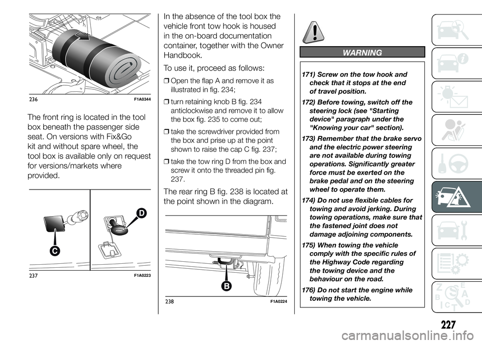
The front ring is located in the tool
box beneath the passenger side
seat. On versions with Fix&Go
kit and without spare wheel, the
tool box is available only on request
for versions/markets where
provided.In the absence of the tool box the
vehicle front tow hook is housed
in the on-board documentation
container, together with the Owner
Handbook.
To use it, proceed as follows:
❒Open the flap A and remove it as
illustrated in fig. 234;
❒turn retaining knob B fig. 234
anticlockwise and remove it to allow
the box fig. 235 to come out;
❒take the screwdriver provided from
the box and prise up at the point
shown to raise the cap C fig. 237;
❒take the tow ring D from the box and
screw it onto the threaded pin fig.
237.
The rear ring B fig. 238 is located at
the point shown in the diagram.
WARNING
171) Screw on the tow hook and
check that it stops at the end
of travel position.
172) Before towing, switch off the
steering lock (see "Starting
device" paragraph under the
"Knowing your car" section).
173) Remember that the brake servo
and the electric power steering
are not available during towing
operations. Significantly greater
force must be exerted on the
brake pedal and on the steering
wheel to operate them.
174) Do not use flexible cables for
towing and avoid jerking. During
towing operations, make sure that
the fastened joint does not
damage adjoining components.
175) When towing the vehicle
comply with the specific rules of
the Highway Code regarding
the towing device and the
behaviour on the road.
176) Do not start the engine while
towing the vehicle.
236F1A0344
237F1A0223
238F1A0224
227
Page 247 of 367
52) 53)
191) 192)
4)
USEFUL ADVICE FOR
EXTENDING THE LIFE
OF YOUR BATTERY
To avoid draining your battery and
make it last longer, observe the
following instructions:
❒when you park the vehicle, ensure
that the doors, tailgate and bonnet
are closed properly, to prevent any
roof lights from remaining on inside
the passenger's compartment;
❒switch off all roof lights inside the
vehicle: the vehicle is however
equipped with a system which
switches all internal lights off
automatically;
❒do not keep accessories (e.g. sound
system, hazard lights, etc.) switched
on for a long time when the engine
is not running;
❒before carrying out any operation on
the electrical system, disconnect the
negative battery cable through the
suitable terminal;
❒Completely tighten the battery
terminals.
IMPORTANT After turning the
ignition key to STOP and having
closed the driver side door, wait at
least one minute before
disconnecting the electrical supply
from the battery. When
reconnecting the electrical supply
to the battery, make sure that
the ignition key is in the STOP
position and the driver side door is
closed.
IMPORTANT If the charge level
remains under 50% for a long time,
the battery is damaged by
sulphation, reducing its capacity
and efficiency at start-up.
The battery is also more prone to
the risk of freezing (at temperatures
as high as -10°C).
Refer to the paragraph "Car
inactivity" in "Starting and driving" if
the car is left parked for a long
time.If, after buying the vehicle, you want
to install electrical accessories
which require permanent electric
supply (alarm, etc.) or accessories
that in any case burden the
electrical supply, contact a Fiat
Dealership, whose qualified
personnel, in addition to suggesting
the most suitable devices from
Lineaccessori Fiat, will evaluate the
overall electrical consumption,
checking whether the vehicle’s
electrical system is capable of
withstanding the load required, or
whether it should be integrated with
a more powerful battery.
Since some of these devices
continue to consume electricity
even when the engine is off, they
gradually run down the battery.
IMPORTANT If a tachograph is
fitted, if the vehicle is parked for a
long period of 5 days, it is advisable
to disconnect the negative battery
terminal to maintain its charge.
243
If the vehicle is equipped with a
battery disconnection function
(disconnector), see the description
of the procedure in the "Controls"
paragraph in the "Dashboard and
controls" section.