window FIAT DUCATO BASE CAMPER 2015 Owner handbook (in English)
[x] Cancel search | Manufacturer: FIAT, Model Year: 2015, Model line: DUCATO BASE CAMPER, Model: FIAT DUCATO BASE CAMPER 2015Pages: 367, PDF Size: 19.73 MB
Page 78 of 367
The dead lock device therefore
offers the best possible protection
against break-in attempts. We
recommend engaging it whenever
the vehicle is parked and left
unattended.
34)
Device activation
The dead lock device is
automatically activated on every
door with two short presses on the
button
on the key with remote
control fig. 104.
Device activation is indicated by 3
flashes of the direction indicators
and a flash of the LED on button A
fig. 107 on the dashboard.If one or more of the doors is not
perfectly shut, the dead lock device
will not be activated, thus
preventing a person getting into the
car through the open door and,
on shutting, it, remaining stuck
inside the passenger compartment.
Device deactivation
The system is disabled
automatically on every door in the
following cases:❒if the mechanical key is turned to the
opening position in the driver's door;
❒by unlocking the doors using the
remote control;
❒by turning the ignition key to the
MAR-ON position.
SLIDING SIDE DOOR
35) 36)
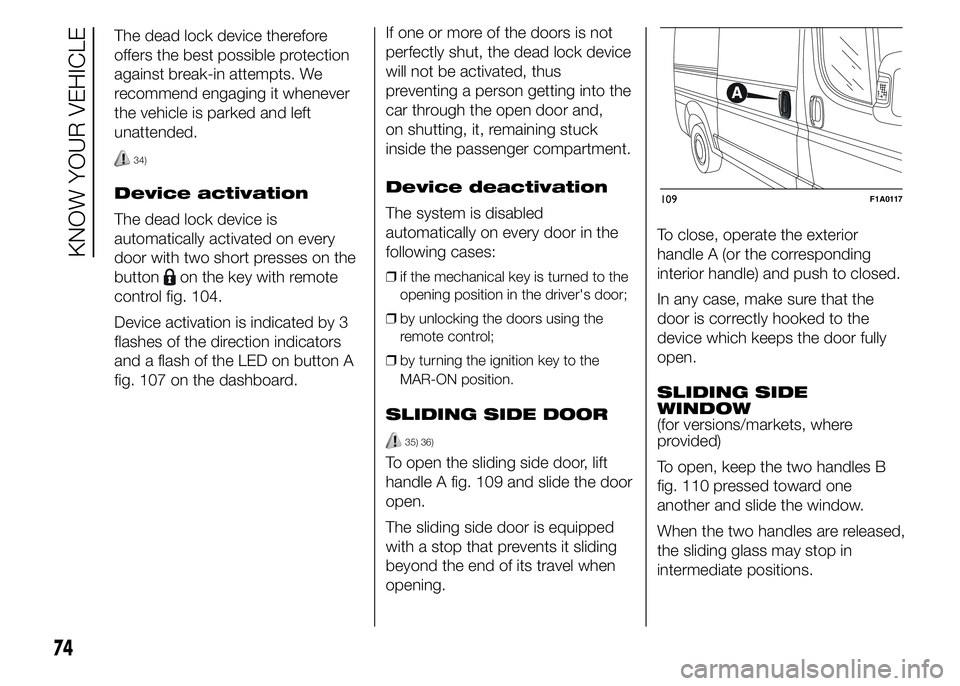
To open the sliding side door, lift
handle A fig. 109 and slide the door
open.
The sliding side door is equipped
with a stop that prevents it sliding
beyond the end of its travel when
opening.To close, operate the exterior
handle A (or the corresponding
interior handle) and push to closed.
In any case, make sure that the
door is correctly hooked to the
device which keeps the door fully
open.
SLIDING SIDE
WINDOW
(for versions/markets, where
provided)
To open, keep the two handles B
fig. 110 pressed toward one
another and slide the window.
When the two handles are released,
the sliding glass may stop in
intermediate positions.
109F1A0117
74
KNOW YOUR VEHICLE
Page 80 of 367
Manual opening of the
second swing door
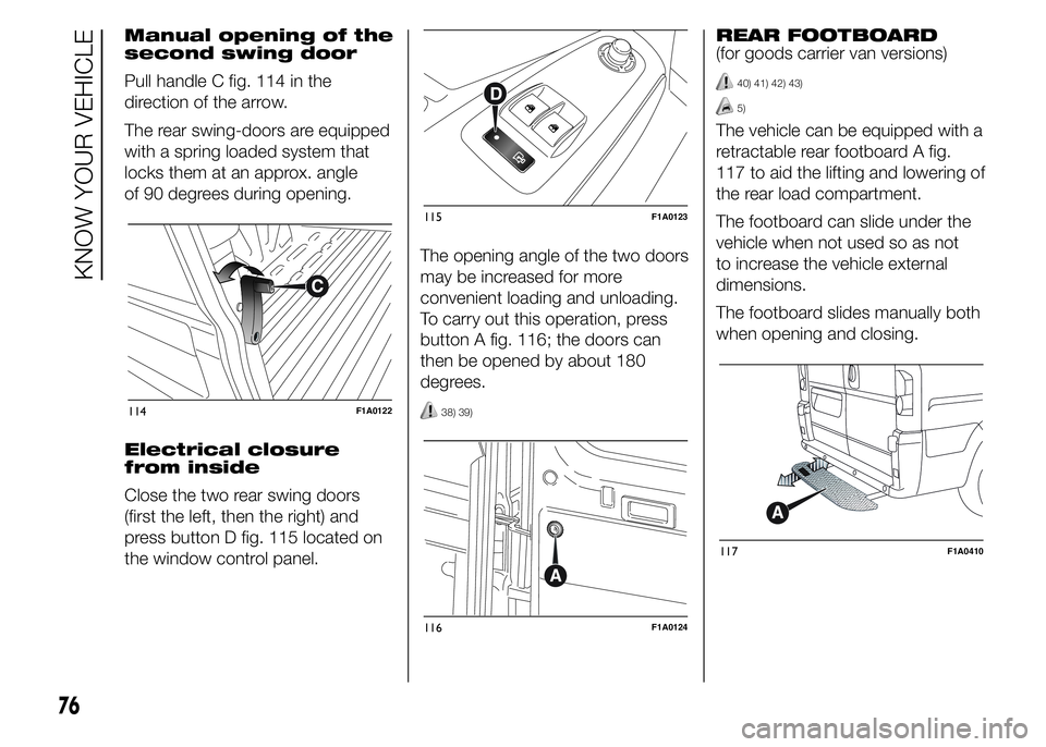
Pull handle C fig. 114 in the
direction of the arrow.
The rear swing-doors are equipped
with a spring loaded system that
locks them at an approx. angle
of 90 degrees during opening.
Electrical closure
from inside
Close the two rear swing doors
(first the left, then the right) and
press button D fig. 115 located on
the window control panel.The opening angle of the two doors
may be increased for more
convenient loading and unloading.
To carry out this operation, press
button A fig. 116; the doors can
then be opened by about 180
degrees.
38) 39)
REAR FOOTBOARD
(for goods carrier van versions)
40) 41) 42) 43)
5)
The vehicle can be equipped with a
retractable rear footboard A fig.
117 to aid the lifting and lowering of
the rear load compartment.
The footboard can slide under the
vehicle when not used so as not
to increase the vehicle external
dimensions.
The footboard slides manually both
when opening and closing.
114F1A0122
115F1A0123
116F1A0124
117F1A0410
76
KNOW YOUR VEHICLE
Page 82 of 367
ELECTRIC WINDOWS
ELECTRIC
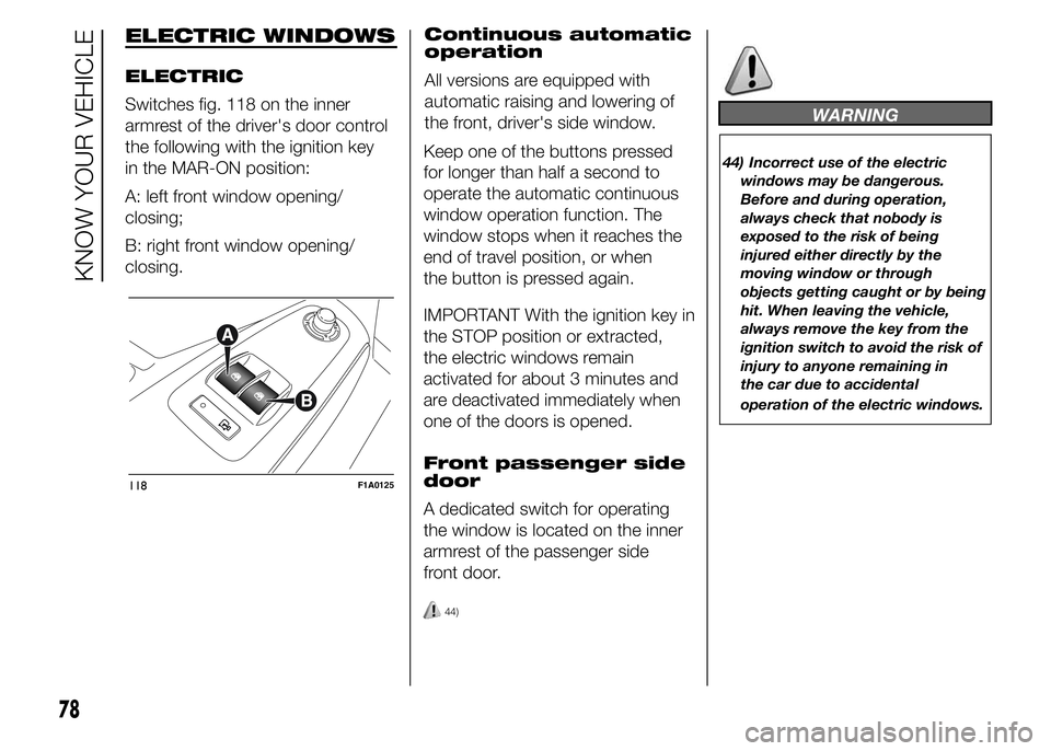
Switches fig. 118 on the inner
armrest of the driver's door control
the following with the ignition key
in the MAR-ON position:
A: left front window opening/
closing;
B: right front window opening/
closing.Continuous automatic
operation
All versions are equipped with
automatic raising and lowering of
the front, driver's side window.
Keep one of the buttons pressed
for longer than half a second to
operate the automatic continuous
window operation function. The
window stops when it reaches the
end of travel position, or when
the button is pressed again.
IMPORTANT With the ignition key in
the STOP position or extracted,
the electric windows remain
activated for about 3 minutes and
are deactivated immediately when
one of the doors is opened.
Front passenger side
door
A dedicated switch for operating
the window is located on the inner
armrest of the passenger side
front door.
44)
WARNING
44) Incorrect use of the electric
windows may be dangerous.
Before and during operation,
always check that nobody is
exposed to the risk of being
injured either directly by the
moving window or through
objects getting caught or by being
hit. When leaving the vehicle,
always remove the key from the
ignition switch to avoid the risk of
injury to anyone remaining in
the car due to accidental
operation of the electric windows.
118F1A0125
78
KNOW YOUR VEHICLE
Page 96 of 367
DRIVING ADVISOR
(lane crossing warning)
(for versions/markets, where
provided)
82) 79) 80)
The Driving Advisor is a warning
system that notifies the driver
if he/she crosses the lane because
he/she has been distracted.
A video sensor, fitted on the
windscreen near the interior rear
view mirror, detects the lane
demarcation lines and the position
of the car in relation to them.
IMPORTANT On cars with Driving
Advisor, it is advisable to contact
a Fiat Dealership should the
windscreen need to be replaced. If
the repair is carried out at a
specialist window replacement
centre, it is still necessary to go to a
Fiat Dealership to have the camera
calibrated.OPERATION
The system is always active when
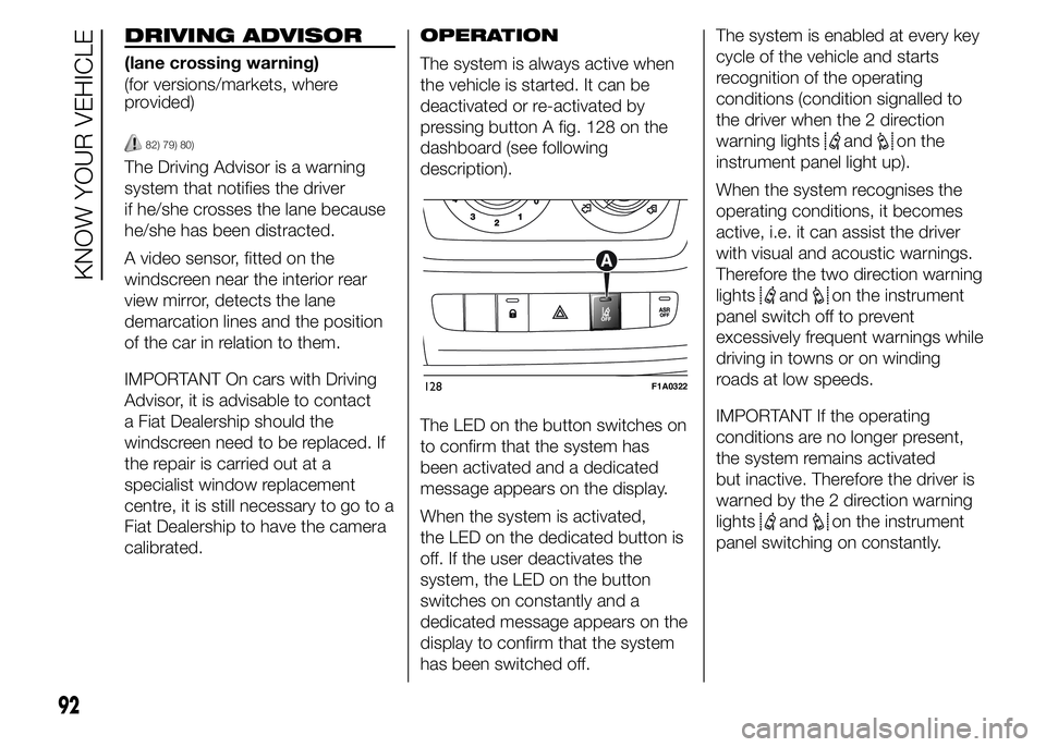
the vehicle is started. It can be
deactivated or re-activated by
pressing button A fig. 128 on the
dashboard (see following
description).
The LED on the button switches on
to confirm that the system has
been activated and a dedicated
message appears on the display.
When the system is activated,
the LED on the dedicated button is
off. If the user deactivates the
system, the LED on the button
switches on constantly and a
dedicated message appears on the
display to confirm that the system
has been switched off.The system is enabled at every key
cycle of the vehicle and starts
recognition of the operating
conditions (condition signalled to
the driver when the 2 direction
warning lights
andon the
instrument panel light up).
When the system recognises the
operating conditions, it becomes
active, i.e. it can assist the driver
with visual and acoustic warnings.
Therefore the two direction warning
lights
andon the instrument
panel switch off to prevent
excessively frequent warnings while
driving in towns or on winding
roads at low speeds.
IMPORTANT If the operating
conditions are no longer present,
the system remains activated
but inactive. Therefore the driver is
warned by the 2 direction warning
lights
andon the instrument
panel switching on constantly.
128F1A0322
92
KNOW YOUR VEHICLE
Page 179 of 367
SIDE BAGS
116) 117) 118) 119) 120) 121) 122) 123) 124) 125)
126) 127) 128)
The vehicle is fitted with front side
bags for driver and passenger
(for versions/markets where
provided) for protecting the chest
and window bags (for versions/
markets where provided) for
protecting front and rear
passengers' heads.
Side bags (for versions/markets
where provided) protect occupants
from side impacts of medium-high
severity, by placing the bag
between the occupant and the
internal parts of the side structure
of the vehicle. Non-activation of
side bags in other types of
collisions (front collisions, rear
shunts, roll-overs, etc...) is not a
system malfunction.
An electronic control unit causes
the bags to inflate in the event of a
side impact. The bags inflate
instantaneously placing themselves
between the occupants' bodies
and the structures which could
cause injury. They deflate
immediately afterwards.Side bags (for versions/markets
where provided) are not a
replacement of but complementary
to the belts, which you are
recommended to always wear, as
specified by law in Europe and
most non-European countries.
FRONT SIDE BAGS
FOR CHEST
PROTECTION
(for versions/markets, where
provided)
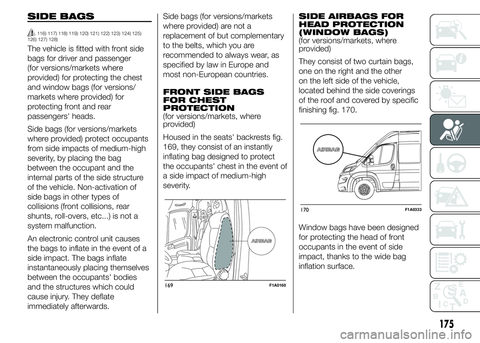
Housed in the seats' backrests fig.
169, they consist of an instantly
inflating bag designed to protect
the occupants' chest in the event of
a side impact of medium-high
severity.SIDE AIRBAGS FOR
HEAD PROTECTION
(WINDOW BAGS)
(for versions/markets, where
provided)
They consist of two curtain bags,
one on the right and the other
on the left side of the vehicle,
located behind the side coverings
of the roof and covered by specific
finishing fig. 170.
Window bags have been designed
for protecting the head of front
occupants in the event of side
impact, thanks to the wide bag
inflation surface.
169F1A0160
170F1A0333
175
Page 180 of 367

IMPORTANT In the event of a
side-on crash, the system offers
best protection if you keep a
correct position on the seat
because this allows the side bags
to inflate correctly.
IMPORTANT The front airbags
and/or side bags may be deployed
if the vehicle is subject to heavy
knocks or accidents involving the
underbody area, such as for
example violent shocks, against
steps, kerbs or low obstacles,
vehicle falling into big potholes or
depressions in the road.
IMPORTANT A small amount of
dust will be released when the
airbags are deployed. The dust is
not harmful and does not indicate
the beginning of a fire. Furthermore,
the surface of the deployed bag
and the interior of the vehicle may
be covered in a dusty residue:
this may irritate your skin and eyes.
Wash with mild soap and water in
the event of exposure.IMPORTANT Should an accident
occur in which any of the safety
devices are activated, take the
vehicle to a Fiat Dealership to have
the activated devices replaced
and to have the whole system
checked.
Every control, repair and
replacement operation concerning
the airbags must only be carried
out at a Fiat Dealership.
If you are having the vehicle
scrapped, have the system
deactivated at a Fiat Dealership
first. If the vehicle changes
ownership, the new owner must be
informed of how to use the airbags
and the above warnings and also
be given this "Owner Handbook".
IMPORTANT Pretensioners, front
airbags and front side bags are
deployed differently according to
the type of collision. Failure to
deploy of one of the devices does
not necessarily indicate a system
malfunction.
WARNING
116) Never rest your head, arms or
elbows on the doors, on the
windows or in the window bag
area as this could cause injuries
during the inflation phase.
117) Never lean your head, arms and
elbows out of the window.
118) If when turning the key to
MAR-ON the warning light
does not turn on or if it stays
on when travelling (together with
the message on the multifunction
display, for versions/markets
where provided), there could be a
fault in the safety systems; in
this event, airbags or
pretensioners may not trigger in
the case of impact or, in a lower
number of cases, they could be
triggered accidentally. Contact a
Fiat Dealership immediately to
have the system checked.
119) Do not cover the backrest of
the front or rear seats with covers
which are not suitable for use
with side bags.
176
SAFETY
Page 189 of 367
SAVING FUEL
Some useful tips are given below
for fuel saving and reducing harmful
emissions of CO2 and other
pollutants (nitrogen oxides, unburnt
hydrocarbons, Particulate Matter
(PM), etc.).
GENERAL
CONSIDERATIONS
The general factors that affect fuel
consumption are listed below.
Vehicle maintenance
Have checks and adjustments
carried out in accordance with the
“Scheduled Servicing Plan”.
Tyres
Check the tyre pressures at least
once every four weeks: if the
pressure is too low, consumption
levels increase as resistance to
rolling is higher.Unnecessary loads
Do not travel with an overloaded
luggage compartment. The weight
of the vehicle (especially when
driving in town) and its geometry
greatly affect fuel consumption and
stability.
Roof rack/ski rack
Remove the roof rack or the ski
rack from the roof after use. These
accessories decrease aerodynamic
penetration of the vehicle and
have a negative effect on fuel
consumption. When transporting
particularly large objects, use a
trailer if possible.
Electric devices
Use electrical devices only for the
amount of time needed. The heated
rear window, additional headlights,
windscreen/rear window wipers
and heater fan need a considerable
amount of energy, therefore
increasing fuel consumption (by up
to 25% in the urban cycle).Climate control
system
Air conditioning leads to higher fuel
consumption (on average up to
+20%). If the temperature outside
permits, try and use the ventilation
only.
Devices for
aerodynamic control
The use of non-certified spoilers
may adversely affect air drag and
fuel consumption.
DRIVING STYLE
The main driving styles that affect
fuel consumption are listed below.
Cranking
Do not warm up the engine at low
or high revs when the vehicle is
stationary; this causes the engine
to warm up more slowly, thereby
increasing fuel consumption and
emissions. It is therefore advisable
to move off immediately, slowly,
avoiding high speeds: in this way
the engine will warm up more
quickly.
185
Page 200 of 367
IMPORTANT
43) Keep your speed down when
snow chains are fitted; do not
exceed 50 km/h. Avoid potholes,
steps and pavements and avoid
driving for long distances on
roads not covered with snow to
prevent damaging the vehicle and
the roadbed.
PROLONGED
VEHICLE INACTIVITY
If the vehicle needs to be off the
road for longer than one month, the
following precautions must be
taken:
❒park the vehicle indoors in a dry and,
if possible, well-ventilated place;
❒engage a gear;
❒check that the handbrake is not
engaged;
❒disconnect the negative battery
terminal; if the vehicle is equipped
with a battery disconnection function
(disconnector), see the description
of the procedure in the "Controls"
paragraph in the "Dashboard and
controls" section;
❒clean and protect the painted parts
using protective wax;
❒clean and protect the shiny metal
parts using special compounds
available commercially;
❒sprinkle talcum powder on the
windscreen and rear window wiper
rubber blades and lift them off the
glass;
❒slightly open the windows;❒cover the vehicle with a piece of
fabric or perforated plastic sheet. Do
not use compact plastic tarpaulins,
which prevent humidity from
evaporating from the surface of the
vehicle;
❒inflate tyres to +0.5 bar above the
standard specified pressure and
check it at intervals;
❒do not drain the engine cooling
system.
IMPORTANT If the vehicle is
equipped with an alarm system,
switch off the vehicle alarm with the
remote control.
IMPORTANT After turning the
ignition key to STOP and having
closed the driver side door, wait at
least one minute before
disconnecting the electrical supply
from the battery. When
reconnecting the electrical supply
to the battery, make sure that
the ignition key is in the STOP
position and the driver side door is
closed.
196
STARTING AND DRIVING
Page 205 of 367
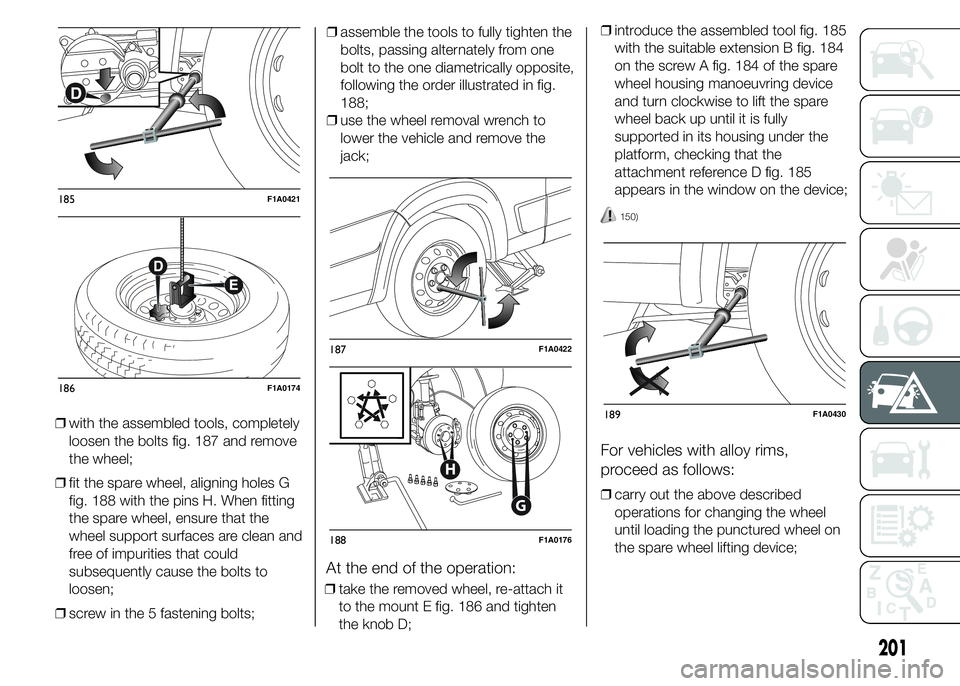
❒with the assembled tools, completely
loosen the bolts fig. 187 and remove
the wheel;
❒fit the spare wheel, aligning holes G
fig. 188 with the pins H. When fitting
the spare wheel, ensure that the
wheel support surfaces are clean and
free of impurities that could
subsequently cause the bolts to
loosen;
❒screw in the 5 fastening bolts;❒assemble the tools to fully tighten the
bolts, passing alternately from one
bolt to the one diametrically opposite,
following the order illustrated in fig.
188;
❒use the wheel removal wrench to
lower the vehicle and remove the
jack;
At the end of the operation:
❒take the removed wheel, re-attach it
to the mount E fig. 186 and tighten
the knob D;❒introduce the assembled tool fig. 185
with the suitable extension B fig. 184
on the screw A fig. 184 of the spare
wheel housing manoeuvring device
and turn clockwise to lift the spare
wheel back up until it is fully
supported in its housing under the
platform, checking that the
attachment reference D fig. 185
appears in the window on the device;
150)
For vehicles with alloy rims,
proceed as follows:
❒carry out the above described
operations for changing the wheel
until loading the punctured wheel on
the spare wheel lifting device;
185F1A0421
186F1A0174
187F1A0422
G
H
188F1A0176
189F1A0430
201
Page 206 of 367
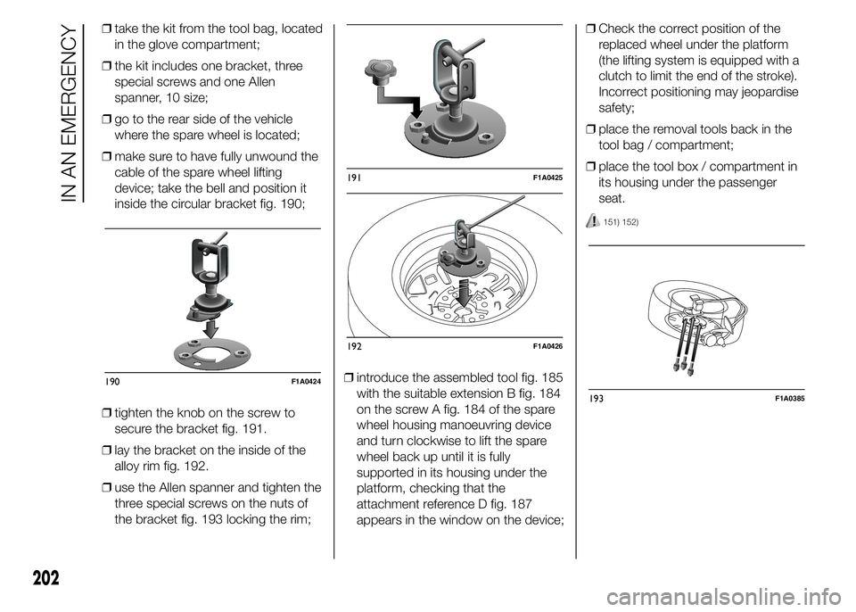
❒take the kit from the tool bag, located
in the glove compartment;
❒the kit includes one bracket, three
special screws and one Allen
spanner, 10 size;
❒go to the rear side of the vehicle
where the spare wheel is located;
❒make sure to have fully unwound the
cable of the spare wheel lifting
device; take the bell and position it
inside the circular bracket fig. 190;
❒tighten the knob on the screw to
secure the bracket fig. 191.
❒lay the bracket on the inside of the
alloy rim fig. 192.
❒use the Allen spanner and tighten the
three special screws on the nuts of
the bracket fig. 193 locking the rim;❒introduce the assembled tool fig. 185
with the suitable extension B fig. 184
on the screw A fig. 184 of the spare
wheel housing manoeuvring device
and turn clockwise to lift the spare
wheel back up until it is fully
supported in its housing under the
platform, checking that the
attachment reference D fig. 187
appears in the window on the device;❒Check the correct position of the
replaced wheel under the platform
(the lifting system is equipped with a
clutch to limit the end of the stroke).
Incorrect positioning may jeopardise
safety;
❒place the removal tools back in the
tool bag / compartment;
❒place the tool box / compartment in
its housing under the passenger
seat.
151) 152)
190F1A0424
191F1A0425
192F1A0426
193F1A0385
202
IN AN EMERGENCY