spare wheel FIAT DUCATO BASE CAMPER 2015 Owner handbook (in English)
[x] Cancel search | Manufacturer: FIAT, Model Year: 2015, Model line: DUCATO BASE CAMPER, Model: FIAT DUCATO BASE CAMPER 2015Pages: 367, PDF Size: 19.73 MB
Page 95 of 367
IMPORTANT
INFORMATION
WARNING
69) The TPMS is optimised for the
original tyres and wheels
provided. TPMS pressures and
alerts have been defined
according to the size of the tyres
mounted on the vehicle. Using
equipment with different size,
type or kind may cause irregular
system operation or sensor
damage. Non-original spare
wheels can damage the sensor.
Do not use tyre sealant or
balancing weights if the vehicle is
equipped with TPMS as these
may damage the sensors.
70) If the system signals a pressure
decrease on a specific tyre, it is
recommended to check the
pressure on all four tyres.
71) TPMS does not relieve the driver
from the obligation to check the
tyre pressure every month; it is
not even to be considered a
replacing system for maintenance
or a safety system.72) Tyre pressure must be checked
with tyres cold. Should it become
necessary for whatever reason
to check pressure with warm
tyres, do not reduce pressure
even if it is higher than the
prescribed value, but repeat the
check when tyres are cold.
73) The TPMS cannot indicate
sudden tyre pressure drops (for
example when a tyre bursts).
In this case, stop the car, braking
with caution and avoiding abrupt
steering.
74) The system only warns that the
tyre pressure is low: it is not able
to inflate them.
75) An insufficient tyre inflation
increases fuel consumption,
reduces the tread duration and
may affect the capacity of driving
safely.
76) Always refit the valve stem cap
after inspecting or adjusting tyre
pressure. This prevents dampness
or dirt from entering the valve
stem and thus the pressure
control sensor from being
damaged.77) The tyre repair kit (Fix&Go)
provided with the car (for
versions/markets, where
provided) is compatible with the
TPMS sensors; using sealants not
equivalent with that in the original
kit may adversely affect its
operation. If sealants not
equivalent with the original one
are used, it is recommended to
have the TPMS sensor operation
checked by a qualified repair
centre.
91
Page 203 of 367
REPLACING A
WHEEL
GENERAL
INSTRUCTIONS
Wheel replacement and correct use
of the jack and spare wheel (for
versions/markets, where provided)
call for some precautions, which
are listed below.
141) 142) 143) 144) 145)
Please note that:
❒the jack weight is 4.5 kg;
❒the jack requires no adjustment;
❒the jack cannot be repaired: in the
event of a fault it must be replaced by
another original one;
❒no tool other than its cranking device
may be fitted on the jack.
146)
To change a wheel,
proceed as follows:
❒stop the vehicle in a position that is
not dangerous for oncoming traffic
where you can change the wheel
safely. The ground should be flat
if possible, and sufficiently firm;❒stop the engine and pull the
handbrake;
❒engage first gear or reverse;
❒put on the reflective safety jacket
(compulsory by law in certain
countries) before getting out of the
vehicle;
❒indicate that the vehicle has broken
down using the devices required by
the law in the current country (e.g.
warning triangle, hazard lights, etc.);
❒In the event of a wheel change on a
slope or on unsurfaced roads, put
any object as stop under the wheels;
❒take the tool bag under the
passenger seat (see “Compartment
under front passenger seat” in the
“Know your vehicle” section);
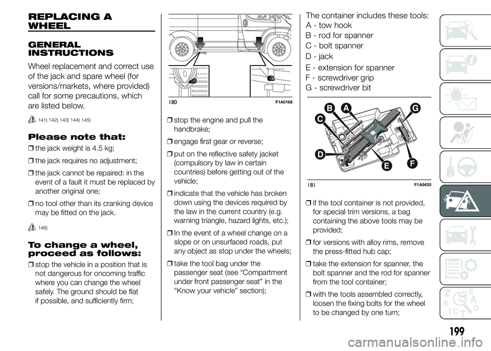
The container includes these tools:
A - tow hook
B - rod for spanner
C - bolt spanner
D - jack
E - extension for spanner
F - screwdriver grip
G - screwdriver bit
❒if the tool container is not provided,
for special trim versions, a bag
containing the above tools may be
provided;
❒for versions with alloy rims, remove
the press-fitted hub cap;
❒take the extension for spanner, the
bolt spanner and the rod for spanner
from the tool container;
❒with the tools assembled correctly,
loosen the fixing bolts for the wheel
to be changed by one turn;
180F1A0168
181F1A0420
199
Page 204 of 367
❒turn the ring nut to partly extend the
jack;
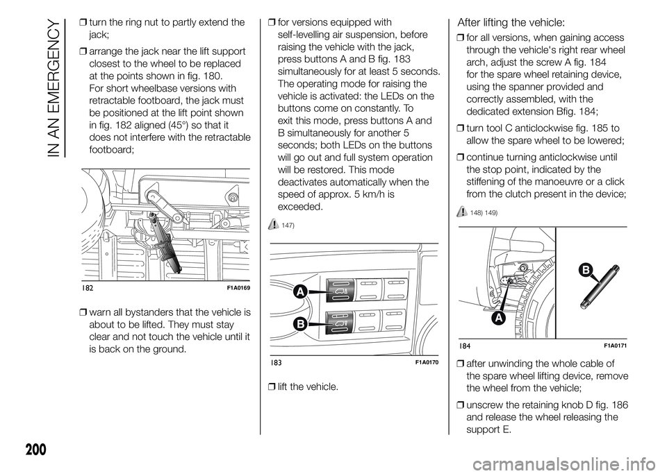
❒arrange the jack near the lift support
closest to the wheel to be replaced
at the points shown in fig. 180.
For short wheelbase versions with
retractable footboard, the jack must
be positioned at the lift point shown
in fig. 182 aligned (45°) so that it
does not interfere with the retractable
footboard;
❒warn all bystanders that the vehicle is
about to be lifted. They must stay
clear and not touch the vehicle until it
is back on the ground.❒for versions equipped with
self-levelling air suspension, before
raising the vehicle with the jack,
press buttons A and B fig. 183
simultaneously for at least 5 seconds.
The operating mode for raising the
vehicle is activated: the LEDs on the
buttons come on constantly. To
exit this mode, press buttons A and
B simultaneously for another 5
seconds; both LEDs on the buttons
will go out and full system operation
will be restored. This mode
deactivates automatically when the
speed of approx. 5 km/h is
exceeded.
147)
❒lift the vehicle.
After lifting the vehicle:
❒for all versions, when gaining access
through the vehicle's right rear wheel
arch, adjust the screw A fig. 184
for the spare wheel retaining device,
using the spanner provided and
correctly assembled, with the
dedicated extension Bfig. 184;
❒turn tool C anticlockwise fig. 185 to
allow the spare wheel to be lowered;
❒continue turning anticlockwise until
the stop point, indicated by the
stiffening of the manoeuvre or a click
from the clutch present in the device;
148) 149)
❒after unwinding the whole cable of
the spare wheel lifting device, remove
the wheel from the vehicle;
❒unscrew the retaining knob D fig. 186
and release the wheel releasing the
support E.
182F1A0169
183F1A0170
184F1A0171
200
IN AN EMERGENCY
Page 205 of 367
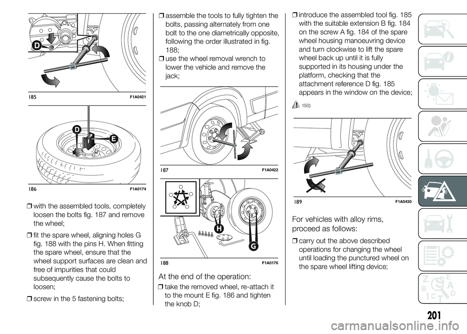
❒with the assembled tools, completely
loosen the bolts fig. 187 and remove
the wheel;
❒fit the spare wheel, aligning holes G
fig. 188 with the pins H. When fitting
the spare wheel, ensure that the
wheel support surfaces are clean and
free of impurities that could
subsequently cause the bolts to
loosen;
❒screw in the 5 fastening bolts;❒assemble the tools to fully tighten the
bolts, passing alternately from one
bolt to the one diametrically opposite,
following the order illustrated in fig.
188;
❒use the wheel removal wrench to
lower the vehicle and remove the
jack;
At the end of the operation:
❒take the removed wheel, re-attach it
to the mount E fig. 186 and tighten
the knob D;❒introduce the assembled tool fig. 185
with the suitable extension B fig. 184
on the screw A fig. 184 of the spare
wheel housing manoeuvring device
and turn clockwise to lift the spare
wheel back up until it is fully
supported in its housing under the
platform, checking that the
attachment reference D fig. 185
appears in the window on the device;
150)
For vehicles with alloy rims,
proceed as follows:
❒carry out the above described
operations for changing the wheel
until loading the punctured wheel on
the spare wheel lifting device;
185F1A0421
186F1A0174
187F1A0422
G
H
188F1A0176
189F1A0430
201
Page 206 of 367
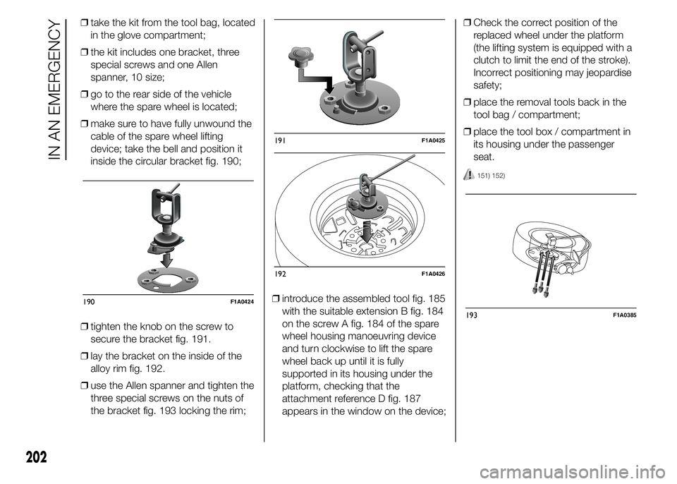
❒take the kit from the tool bag, located
in the glove compartment;
❒the kit includes one bracket, three
special screws and one Allen
spanner, 10 size;
❒go to the rear side of the vehicle
where the spare wheel is located;
❒make sure to have fully unwound the
cable of the spare wheel lifting
device; take the bell and position it
inside the circular bracket fig. 190;
❒tighten the knob on the screw to
secure the bracket fig. 191.
❒lay the bracket on the inside of the
alloy rim fig. 192.
❒use the Allen spanner and tighten the
three special screws on the nuts of
the bracket fig. 193 locking the rim;❒introduce the assembled tool fig. 185
with the suitable extension B fig. 184
on the screw A fig. 184 of the spare
wheel housing manoeuvring device
and turn clockwise to lift the spare
wheel back up until it is fully
supported in its housing under the
platform, checking that the
attachment reference D fig. 187
appears in the window on the device;❒Check the correct position of the
replaced wheel under the platform
(the lifting system is equipped with a
clutch to limit the end of the stroke).
Incorrect positioning may jeopardise
safety;
❒place the removal tools back in the
tool bag / compartment;
❒place the tool box / compartment in
its housing under the passenger
seat.
151) 152)
190F1A0424
191F1A0425
192F1A0426
193F1A0385
202
IN AN EMERGENCY
Page 207 of 367
WARNING
141) Use your hazard lights, warning
triangle, etc. to show that your
vehicle is stationary according to
the regulations in force.
Passengers should get out of the
vehicle, particularly if it is heavily
loaded, and wait for the wheel
to be changed away from the
traffic. Apply the handbrake. in
the event of a wheel change on a
slope or on unsurfaced roads,
put any object as stop under the
wheels.
142) The spare wheel supplied (for
versions/markets, where
provided) is specific for your
vehicle. Therefore, it must not be
used on other models. Do not
use spare wheels of other models
on your vehicle. The wheel bolts
are specific for your vehicle: do
not use them on different models
and do not use bolts from other
models on your car.143) Have the wheel repaired and
refitted as soon as possible. Do
not apply grease to the bolt
threads before fitting: they could
come unscrewed.
144) Use the jack only to replace
wheels on the vehicle with which
it is supplied or on other vehicles
of the same model. Never use
the jack for other purposes, such
as lifting other car models. Never
use the jack to carry out repairs
under the vehicle. Incorrect
positioning of the jack may cause
the lifted vehicle to fall. Do not
use the jack for loads higher than
those shown on the label.
145) Never tamper with the inflation
valve. Never introduce tools of any
kind between rim and tyre. Check
tyre and spare wheel pressure
regularly, referring to the values
shown in the "Technical
specifications" section.
146) No tools other than the crank
provided should be used with
the spare wheel lifting device; it
should be operated by hand only.147) On versions equipped with
self-levelling air suspension, never
introduce the head or hands in
the wheel arch: the vehicle could
raise or lower automatically
depending on possible load or
temperature changes.
148) The device should only be
operated by hand, without using
any type of tool other than the
crank provided, like pneumatic or
electrical screwers.
149) The moving components of the
jack (screw and joints) can also
cause injuries: do not touch them.
If you come into contact with
lubricating grease, clean yourself
thoroughly.
150) At the end of the operation of
raising/locking the spare wheel,
after having checked the correct
positioning of the wheel under the
platform (yellow notch inside the
window on the device), the
spanner must be extracted, taking
care not to turn it in the wrong
direction (as in fig. 189) to
facilitate the extraction of the
spanner itself, to prevent the
attachment device from being
released and the wheel assembly
not being securely retained.
203
Page 208 of 367
151) Each time the spare wheel is
moved, check that it is correctly
positioned in its housing under
the platform. If it is not correctly
positioned, this could adversely
affect safety.
152) The spare wheel lifting device
is equipped with a clutch safety
system for its own protection; this
could activated if an excessive
load is applied on the
maneuvering screw.FIX&GO
AUTOMATIC QUICK
TYRE REPAIR KIT
(for versions/markets, where
provided)
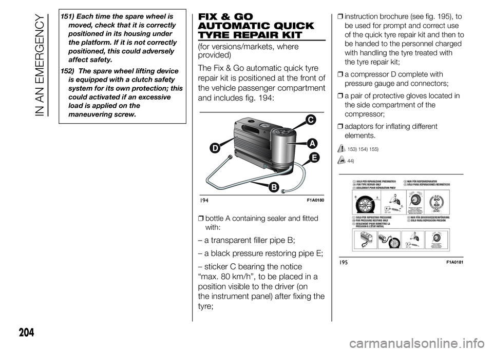
The Fix & Go automatic quick tyre
repair kit is positioned at the front of
the vehicle passenger compartment
and includes fig. 194:
❒bottle A containing sealer and fitted
with:
– a transparent filler pipe B;
– a black pressure restoring pipe E;
– sticker C bearing the notice
“max. 80 km/h”, to be placed in a
position visible to the driver (on
the instrument panel) after fixing the
tyre;
❒instruction brochure (see fig. 195), to
be used for prompt and correct use
of the quick tyre repair kit and then to
be handed to the personnel charged
with handling the tyre treated with
the tyre repair kit;
❒a compressor D complete with
pressure gauge and connectors;
❒a pair of protective gloves located in
the side compartment of the
compressor;
❒adaptors for inflating different
elements.
153) 154) 155)
44)
194F1A0180
195F1A0181
204
IN AN EMERGENCY
Page 231 of 367
The front ring is located in the tool
box beneath the passenger side
seat. On versions with Fix&Go
kit and without spare wheel, the
tool box is available only on request
for versions/markets where
provided.In the absence of the tool box the
vehicle front tow hook is housed
in the on-board documentation
container, together with the Owner
Handbook.
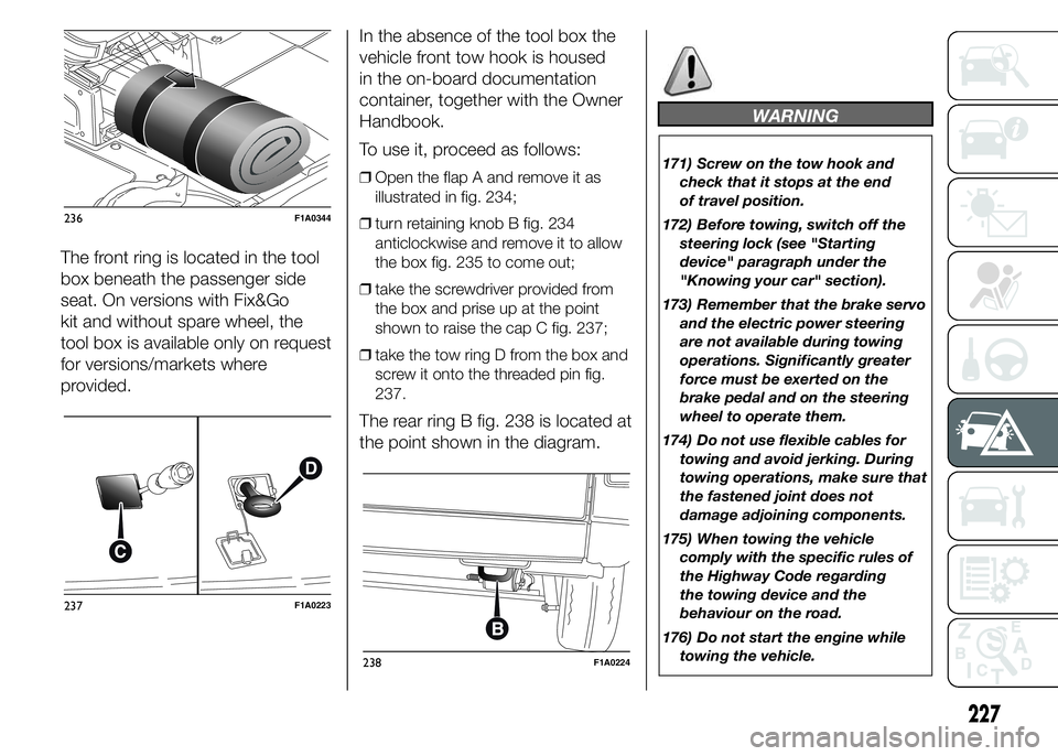
To use it, proceed as follows:
❒Open the flap A and remove it as
illustrated in fig. 234;
❒turn retaining knob B fig. 234
anticlockwise and remove it to allow
the box fig. 235 to come out;
❒take the screwdriver provided from
the box and prise up at the point
shown to raise the cap C fig. 237;
❒take the tow ring D from the box and
screw it onto the threaded pin fig.
237.
The rear ring B fig. 238 is located at
the point shown in the diagram.
WARNING
171) Screw on the tow hook and
check that it stops at the end
of travel position.
172) Before towing, switch off the
steering lock (see "Starting
device" paragraph under the
"Knowing your car" section).
173) Remember that the brake servo
and the electric power steering
are not available during towing
operations. Significantly greater
force must be exerted on the
brake pedal and on the steering
wheel to operate them.
174) Do not use flexible cables for
towing and avoid jerking. During
towing operations, make sure that
the fastened joint does not
damage adjoining components.
175) When towing the vehicle
comply with the specific rules of
the Highway Code regarding
the towing device and the
behaviour on the road.
176) Do not start the engine while
towing the vehicle.
236F1A0344
237F1A0223
238F1A0224
227
Page 249 of 367
WHEELS AND TYRES
Check the pressure of each tyre,
including the space-saver wheel,
approximately every two weeks and
before long journeys: the pressure
should be checked with the tyre
rested and cold.
It is normal for the pressure to
increase when the vehicle is used;
for the correct tyre inflation
pressure, see “Wheels” in the
“Technical specifications” section.
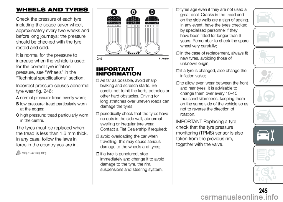
Incorrect pressure causes abnormal
tyre wear fig. 246:
Anormal pressure: tread evenly worn;
Blow pressure: tread particularly worn
at the edges;
Chigh pressure: tread particularly worn
in the centre.
The tyres must be replaced when
the tread is less than 1.6 mm thick.
In any case, follow the laws in
force in the country you are in.
193) 194) 195) 196)
IMPORTANT
INFORMATION
❒As far as possible, avoid sharp
braking and screech starts. Be
careful not to hit the kerb, potholes or
other hard obstacles. Driving for
long stretches over uneven roads can
damage the tyres;
❒periodically check that the tyres have
no cuts in the side wall, abnormal
swelling or irregular tyre wear.
Contact a Fiat Dealership if required;
❒avoid overloading the car when
travelling: this may cause serious
damage to the wheels and tyres;
❒if a tyre is punctured, stop
immediately and change it to avoid
damage to the tyre, the rim,
suspensions and steering system;❒tyres age even if they are not used a
great deal. Cracks in the tread and
on the side walls are a sign of ageing.
In any event, have the tyres checked
by specialised personnel if they
have been fitted for longer than 6
years. Remember to check the spare
wheel very carefully;
❒in the case of replacement, always fit
new tyres, avoiding those of
unknown origin;
❒if a tyre is changed, also change the
inflation valve;
❒to allow even wear between the front
and rear tyres, it is advisable to
change them over every 10–15
thousand kilometres, keeping them
on the same side of the vehicle so as
not to reverse the direction of
rotation.
IMPORTANT Replacing a tyre,
check that the tyre pressure
monitoring (TPMS) sensor is also
taken from the previous rim,
together with the valve.
246F1A0240
245
Page 252 of 367
BODYWORK
PROTECTION AGAINST
ATMOSPHERIC
AGENTS
The main causes of corrosion are
the following:
❒atmospheric pollution;
❒salty air and humidity (coastal areas,
or hot humid climates);
❒seasonal environmental conditions.
The abrasive action of wind-borne
atmospheric dust and sand, as well
as mud and gravel raised by other
vehicles is also not to be
underestimated.
On your vehicle, Fiat has
implemented the best
manufacturing technologies to
effectively protect the bodywork
against corrosion.
These include:
❒painting products and systems which
give the vehicle particular resistance
to corrosion and abrasion;
❒Use of galvanised (or pretreated)
steel sheets, with high resistance
to corrosion;❒spraying the underbody, engine
compartment, wheelhouse internal
parts and other parts with highly
protective wax products;
❒spraying of plastic parts, with a
protective function in the more
exposed points: underdoor, inner
wing, edges, etc;
❒use of “open” boxed sections to
prevent condensation and pockets of
moisture from triggering rust inside.
VEHICLE BODY AND
UNDERBODY
WARRANTY
Your vehicle is covered by warranty
against perforation due to corrosion
of any original element of the
structure or body.
For the general terms of this
warranty, refer to the Warranty
Booklet.
ADVICE FOR
PRESERVING THE
BODYWORK
Paintwork
Paintwork does not only serve an
aesthetic purpose, but also
protects the underlying sheet metal.Touch up abrasions and scratches
immediately to prevent rust
formation. Only use genuine spare
paint products for touch-ups (see
“Bodywork paint identification
plate” in the “Technical
Specifications” section).
Normal maintenance of paintwork
consists in washing the car: the
frequency depends on the
conditions and environment where
the car is used.
For example, it is advisable to wash
the vehicle more often in areas
with high levels of environmental
pollution or on roads spread with
salt.
To correctly wash the vehicle,
proceed as follows:
❒wash the bodywork using a low
pressure jet of water;
❒wipe a sponge with a slightly soapy
solution over the bodywork,
frequently rinsing the sponge;
248
SERVICING AND MAINTENANCE
❒rinse well with water and dry with a
jet of air or a chamois leather.