starting FIAT DUCATO BASE CAMPER 2016 Owner handbook (in English)
[x] Cancel search | Manufacturer: FIAT, Model Year: 2016, Model line: DUCATO BASE CAMPER, Model: FIAT DUCATO BASE CAMPER 2016Pages: 387, PDF Size: 20.76 MB
Page 6 of 387
READ THIS CAREFULLY
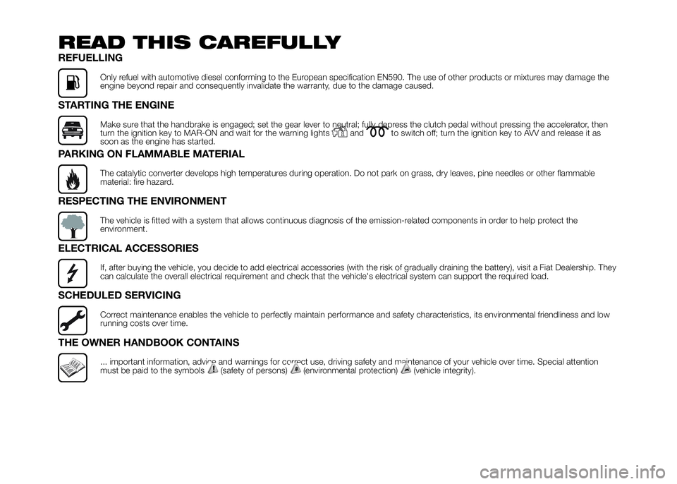
REFUELLING
Only refuel with automotive diesel conforming to the European specification EN590. The use of other products or mixtures may damage the
engine beyond repair and consequently invalidate the warranty, due to the damage caused.
STARTING THE ENGINE
Make sure that the handbrake is engaged; set the gear lever to neutral; fully depress the clutch pedal without pressing the accelerator, then
turn the ignition key to MAR-ON and wait for the warning lightsandto switch off; turn the ignition key to AVV and release it as
soon as the engine has started.
PARKING ON FLAMMABLE MATERIAL
The catalytic converter develops high temperatures during operation. Do not park on grass, dry leaves, pine needles or other flammable
material: fire hazard.
RESPECTING THE ENVIRONMENT
The vehicle is fitted with a system that allows continuous diagnosis of the emission-related components in order to help protect the
environment.
ELECTRICAL ACCESSORIES
If, after buying the vehicle, you decide to add electrical accessories (with the risk of gradually draining the battery), visit a Fiat Dealership. They
can calculate the overall electrical requirement and check that the vehicle's electrical system can support the required load.
SCHEDULED SERVICING
Correct maintenance enables the vehicle to perfectly maintain performance and safety characteristics, its environmental friendliness and low
running costs over time.
THE OWNER HANDBOOK CONTAINS
... important information, advice and warnings for correct use, driving safety and maintenance of your vehicle over time. Special attention
must be paid to the symbols(safety of persons)(environmental protection)(vehicle integrity).
Page 15 of 387
SYMBOLS
Some vehicle components have
coloured labels whose symbols indicate
precautions to be observed when
using this component. Under the
bonnet there is also a label that
summarises all the symbols.
THE FIAT CODE
SYSTEM
IN BRIEF
This is an electrical engine locking
systemwhich increases protection
against attempted theft of the vehicle.
It is automatically activated when
the ignition key is removed.
Each key contains an electronic
device which modulates the signal
emitted during ignition by an antenna
built into the ignition device. The
signal, which changes each time the
engine is started, is the “password”,
by means of which the control unit
recognises the key and enables
starting.
1)
Operation
Each time the vehicle is started turning
the ignition key toMAR-ON, the Fiat
CODE system control unit sends a
recognition code to the Powertrain
Control Module to deactivate the
immobiliser.The acknowledgement code is sent
only if the Fiat CODE system control
unit has recognised the code
transmitted from the key.
Each time the ignition key is turned to
STOP, the Fiat CODE system
deactivates the functions of the
Powertrain Control Module.
Irregular operation
If, during starting, the code has not
been recognised correctly the warning
light
on the instrument panel turns
on accompanied by the related
message on the display (see section
“Warning lights and messages”).
In this case, turn the key toSTOPand
then back toMAR-ON; if the lock
continues, try with the other keys
provided with the vehicle. Contact a
Fiat Dealership if you still cannot start
the engine.
IMPORTANT Each key has its own
code which must be stored by the
system's control unit. Contact the Fiat
Dealership to have new keys (up to
eight) stored with the code.
11
Page 19 of 387
IMPORTANT The alarm is adapted to
meet requirements in various countries.
Disengagement
Press the door release/load
compartment release button on the key
with remote control.
The following operations are performed
(excluding some markets):
❒direction indicators flash twice;
❒there are two short acoustic signals
(beeps);
❒unlocking of the doors.
IMPORTANT The alarm does not switch
off when the central opening is
activated using the metal insert in the
key.
Break-in attempt
indication
Any break-in attempt is indicated by the
turning on of warning light
on the
instrument panel together with the
message on the display (where
provided, see paragraph “Warning
lights and messages” in the “Knowing
the instrument panel” section).Disabling
To permanently disable the alarm (e.g.
during a long period of inactivity), simply
lock the vehicle by turning the metal
insert of the key with remote control in
the lock.
IMPORTANT If the batteries of the key
with the remote control run out or
the system fails, the alarm can
be switched off by placing the key in
the ignition switch and turning it to
MAR-ON.
IGNITION SWITCH
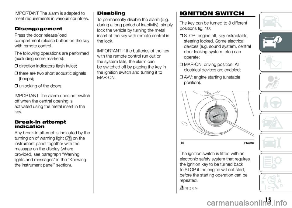
The key can be turned to 3 different
positions fig. 10:
❒STOP: engine off, key extractable,
steering locked. Some electrical
devices (e.g. sound system, central
door locking system, etc.) can
operate;
❒MAR-ON: driving position. All
electrical devices are enabled;
❒AVV: engine starting (unstable
position).
The ignition switch is fitted with an
electronic safety system that requires
the ignition key to be turned back
to STOP if the engine will not start,
before the starting operation can be
repeated.
2) 3) 4) 5)
10F1A0009
15
Page 27 of 387
The seat can be turned 180º toward
the seat on the opposite side. To turn it,
see the "Seat with revolving base"
paragraph.
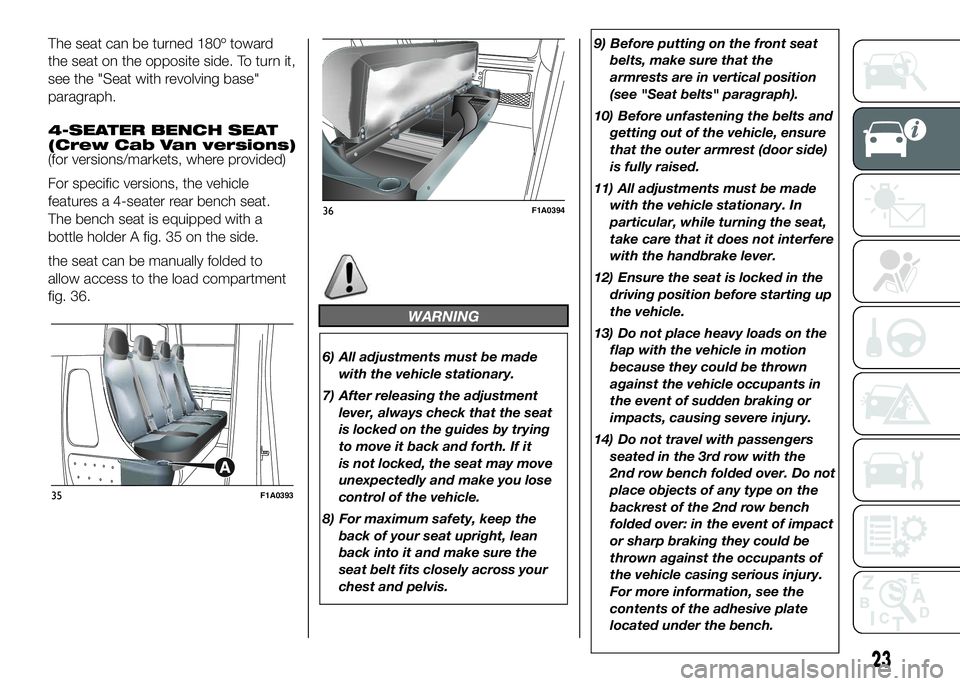
4-SEATER BENCH SEAT
(Crew Cab Van versions)
(for versions/markets, where provided)
For specific versions, the vehicle
features a 4-seater rear bench seat.
The bench seat is equipped with a
bottle holder A fig. 35 on the side.
the seat can be manually folded to
allow access to the load compartment
fig. 36.
WARNING
6) All adjustments must be made
with the vehicle stationary.
7) After releasing the adjustment
lever, always check that the seat
is locked on the guides by trying
to move it back and forth. If it
is not locked, the seat may move
unexpectedly and make you lose
control of the vehicle.
8) For maximum safety, keep the
back of your seat upright, lean
back into it and make sure the
seat belt fits closely across your
chest and pelvis.9) Before putting on the front seat
belts, make sure that the
armrests are in vertical position
(see "Seat belts" paragraph).
10) Before unfastening the belts and
getting out of the vehicle, ensure
that the outer armrest (door side)
is fully raised.
11) All adjustments must be made
with the vehicle stationary. In
particular, while turning the seat,
take care that it does not interfere
with the handbrake lever.
12) Ensure the seat is locked in the
driving position before starting up
the vehicle.
13) Do not place heavy loads on the
flap with the vehicle in motion
because they could be thrown
against the vehicle occupants in
the event of sudden braking or
impacts, causing severe injury.
14) Do not travel with passengers
seated in the 3rd row with the
2nd row bench folded over. Do not
place objects of any type on the
backrest of the 2nd row bench
folded over: in the event of impact
or sharp braking they could be
thrown against the occupants of
the vehicle casing serious injury.
For more information, see the
contents of the adhesive plate
located under the bench.
35F1A0393
36F1A0394
23
Page 45 of 387
ADDITIONAL
HEATER
(for versions/markets, where provided)
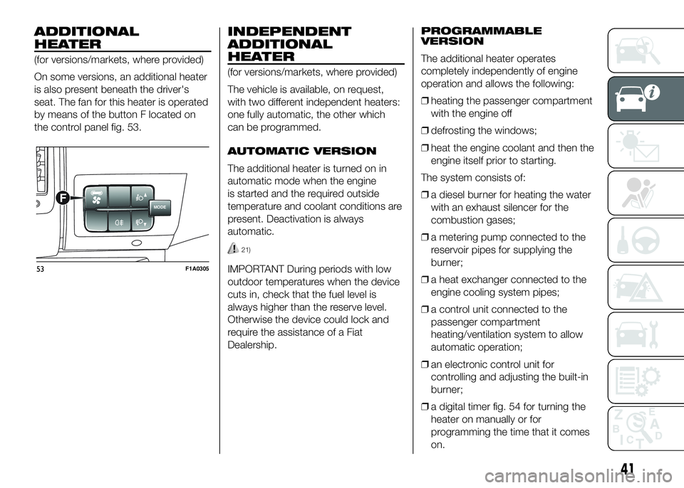
On some versions, an additional heater
is also present beneath the driver's
seat. The fan for this heater is operated
by means of the button F located on
the control panel fig. 53.
INDEPENDENT
ADDITIONAL
HEATER
(for versions/markets, where provided)
The vehicle is available, on request,
with two different independent heaters:
one fully automatic, the other which
can be programmed.
AUTOMATIC VERSION
The additional heater is turned on in
automatic mode when the engine
is started and the required outside
temperature and coolant conditions are
present. Deactivation is always
automatic.
21)
IMPORTANT During periods with low
outdoor temperatures when the device
cuts in, check that the fuel level is
always higher than the reserve level.
Otherwise the device could lock and
require the assistance of a Fiat
Dealership.PROGRAMMABLE
VERSION
The additional heater operates
completely independently of engine
operation and allows the following:
❒heating the passenger compartment
with the engine off
❒defrosting the windows;
❒heat the engine coolant and then the
engine itself prior to starting.
The system consists of:
❒a diesel burner for heating the water
with an exhaust silencer for the
combustion gases;
❒a metering pump connected to the
reservoir pipes for supplying the
burner;
❒a heat exchanger connected to the
engine cooling system pipes;
❒a control unit connected to the
passenger compartment
heating/ventilation system to allow
automatic operation;
❒an electronic control unit for
controlling and adjusting the built-in
burner;
❒a digital timer fig. 54 for turning the
heater on manually or for
programming the time that it comes
on.
MODEF
53F1A0305
41
Page 74 of 387
Automatic adjustment
When moving, the system automatically
shows that the vehicle is in 'ride setting
0' and keeps it constant.
During the adjustment the LED located
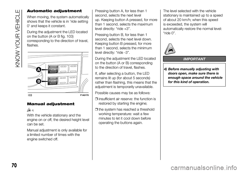
on the button (A or B fig. 103)
corresponding to the direction of travel,
flashes.
Manual adjustment
4)
With the vehicle stationary and the
engine on or off, the desired height level
can be set.
Manual adjustment is only available for
a limited number of times with the
engine switched off.Pressing button A, for less than 1
second, selects the next level
up. Keeping button A pressed, for more
than 1 second, selects the maximum
level directly: “ride +3”.
Pressing button B, for less than 1
second, selects the next level down.
Keeping button B pressed, for more
than 1 second, selects the minimum
level directly: “ride -3”.
During the adjustment the LED located
on the button (A or B) corresponding
to the direction of travel, flashes.
If, after selecting a button, the LED
remains lit up (for about 5 seconds)
rather than flashing, this means that the
adjustment is temporarily unavailable.
Possible causes may be as follows:
❒insufficient air reserve: the function is
restored by starting the engine;
❒the system has reached a threshold
working temperature: wait a few
minutes to let it cool down before
operating the buttons again.The level selected with the vehicle
stationary is maintained up to a speed
of about 20 km/h; when this speed
is exceeded, the system will
automatically restore the normal level:
“ride 0”.
IMPORTANT
4) Before manually adjusting with
doors open, make sure there is
enough space around the vehicle
for this kind of operation.
103F1A0170
70
KNOW YOUR VEHICLE
Page 87 of 387
HILL HOLDER SYSTEM
This system is an integral part of the
ESC system and facilitates starting on
slopes.
It is automatically activated in the
following conditions:
❒uphill: vehicle stationary on a road
with a gradient higher than 5%,
engine running, brake pressed and
gearbox in neutral or gear (other than
reverse) engaged;
❒downhill: vehicle stationary on a road
with a gradient higher than 5%,
engine running, brake pressed and
reverse gear engaged.
When setting off, the ESC system
control unit maintains the braking
pressure on the wheels until the torque
necessary for starting is reached, or
in any case for a maximum of 2
seconds, allowing your right foot to be
moved easily from the brake pedal to
the accelerator.
When two seconds have elapsed,
without starting, the system is
automatically deactivated, gradually
releasing the braking pressure. During
this release stage, the typical brake
disengagement noise indicating that the
vehicle is going to move imminently
will be heard.IMPORTANT The Hill Holder system is
not a parking brake; therefore, never
leave the vehicle without having
engaged the handbrake, turned the
engine off and engaged first gear,
so that it is parked in safe conditions
(for further information read the
"Parking" paragraph in the "Starting
and driving" chapter).
ASR (AntiSlip
Regulation) SYSTEM
It is an integral part of the ESC system.
It automatically operates in the event
of one or both drive wheels slipping,
loss of grip on wet roads (aquaplaning)
and acceleration on slippery, snowy
or icy roads, etc.
Depending on the slipping conditions,
two different control systems are
activated:
❒if the slipping involves both drive
wheels, the ASR intervenes reducing
the power transmitted by the engine;
❒if the slipping only involves one of the
drive wheels, it intervenes
automatically braking the wheel that
is slipping.
62)
Engagement/ disengagement of the
ASR system
The ASR system switches on
automatically each time the engine is
started.
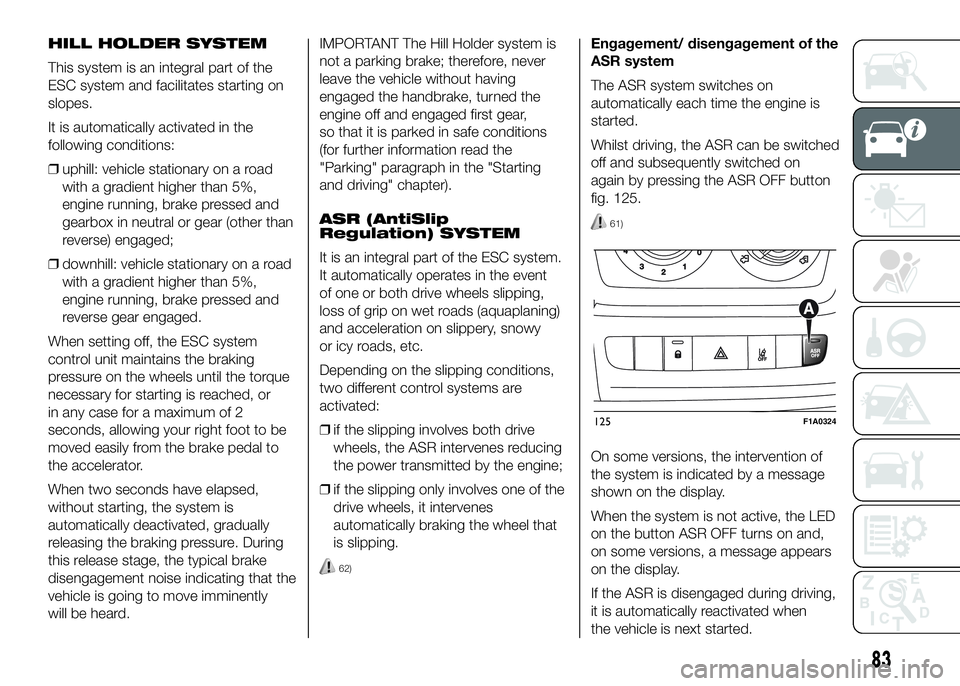
Whilst driving, the ASR can be switched
off and subsequently switched on
again by pressing the ASR OFF button
fig. 125.
61)
On some versions, the intervention of
the system is indicated by a message
shown on the display.
When the system is not active, the LED
on the button ASR OFF turns on and,
on some versions, a message appears
on the display.
If the ASR is disengaged during driving,
it is automatically reactivated when
the vehicle is next started.
125F1A0324
83
Page 91 of 387
Traction Plus operation
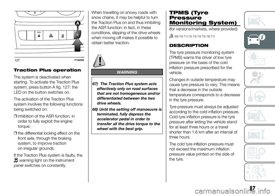
The system is deactivated when
starting. To activate the Traction Plus
system, press button A fig. 127: the
LED on the button switches on.
The activation of the Traction Plus
system involves the following functions
being switched on:
❒inhibition of the ASR function, in
order to fully exploit the engine
torque;
❒the differential locking effect on the
front axle, through the braking
system, to improve traction
on irregular grounds.
If the Traction Plus system is faulty, the
warning light on the instrument
panel switches on constantly.When travelling on snowy roads with
snow chains, it may be helpful to turn
the Traction Plus on and thus inhibiting
the ASR function: in fact, in these
conditions, slipping of the drive wheels
when moving off makes it possible to
obtain better traction.
WARNING
67) The Traction Plus system acts
effectively only on road surfaces
that are not homogeneous and/or
differentiated between the two
drive wheels.
68) Until the setting off manoeuvre is
terminated, fully depress the
accelerator pedal in order to
transfer all the drive torque to the
wheel with the best grip.
TPMS (Tyre
Pressure
Monitoring System)
(for versions/markets, where provided)
69) 70) 71) 72) 73) 74) 75) 76) 77)
DESCRIPTION
The tyre pressure monitoring system
(TPMS) warns the driver of low tyre
pressure on the basis of the cold
inflation pressure prescribed for the
vehicle.
Changes in outside temperature may
cause tyre pressure to vary. This means
that a decrease in the outside
temperature corresponds to a decrease
in the tyre pressure.
Tyre pressure must always be adjusted
according to the cold inflation pressure.
Cold tyre inflation pressure is the tyre
pressure after letting the vehicle stand
for at least three hours or a travel
shorter than 1.6 km after an interval of
three hours.
The cold tyre inflation pressure must
not exceed the maximum inflation
pressure value printed on the side of
the tyre.
127F1A0325
87
Page 106 of 387
WARNING
86) The responsibility for parking
and other dangerous manoeuvres
always and in every case lies
with the driver. While carrying out
these manoeuvres, always make
sure that no people (especially
children) or animals are in the
area concerned. The parking
sensors are used to assist the
driver, who must never allow his
attention to lapse during
potentially dangerous
manoeuvres, even those executed
at low speeds.
START&STOP
SYSTEM
IN BRIEF
The Start&Stop device automatically
stopsthe engine each time the
vehicle is stationary and starts it
again when the driver wants to move
off. This improves the efficiency of
the vehicle by reducing fuel
consumption, the emission of harmful
gases and noise pollution.
OPERATING MODES
Engine stopping mode
WITH MANUAL GEARBOX
With the vehicle stationary, the engine
stops with the gearbox in neutral and
the clutch pedal released.
NoteThe engine can only be stopped
automatically after exceeding a speed
of about 10 km/h, to prevent the engine
from being repeatedly stopped when
driving at walking pace.
Engine stopping is signalled by the
icon on the display.Engine restarting mode
WITH MANUAL GEARBOX
Depress the clutch pedal to restart the
engine.
MANUAL ACTIVATION
AND DEACTIVATION OF
THE SYSTEM
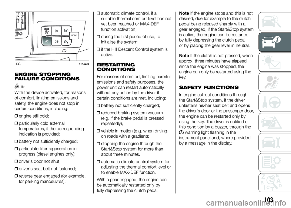
To activate/deactivate the system
manually, press the
fig. 133 button
on the dashboard control trim.
Start&Stop system
activation
A message will appear on the display
when the Start&Stop system is
activated. In this condition, the LED on
the
button is off.
Start&Stop system
deactivation
A message will appear on the display
when the Start&Stop system is
deactivated.
The LED on the
button is on when
the system is deactivated.
102
KNOW YOUR VEHICLE
Page 107 of 387
ENGINE STOPPING
FAILURE CONDITIONS
18)
With the device activated, for reasons
of comfort, limiting emissions and
safety, the engine does not stop in
certain conditions, including:
❒engine still cold;
❒particularly cold external
temperatures, if the corresponding
indication is provided;
❒battery not sufficiently charged;
❒particulate filter regeneration in
progress (diesel engines only);
❒driver's door not shut;
❒driver's seat belt not fastened;
❒reverse gear engaged (for example,
for parking manoeuvres);❒automatic climate control, if a
suitable thermal comfort level has not
yet been reached or MAX-DEF
function activation;
❒during the first period of use, to
initialise the system;
❒if the Hill Descent Control system is
active.
RESTARTING
CONDITIONS
For reasons of comfort, limiting harmful
emissions and safety purposes, the
power unit can restart automatically
without any action by the driver if
certain conditions are met, including:
❒battery not sufficiently charged;
❒reduced braking system vacuum
(e.g. if the brake pedal is pressed
repeatedly);
❒vehicle in motion (e.g. when driving
on roads with a gradient);
❒stopping the engine through the
Start&Stop system for more than
about three minutes.
❒automatic climate control system for
adjusting the thermal comfort level or
to enable MAX-DEF function.
With a gear engaged, the engine can
be automatically restarted only by
fully depressing the clutch pedal.NoteIf the engine stops and this is not
desired, due for example to the clutch
pedal being released sharply with a
gear engaged, if the Start&Stop system
is active, the engine can be restarted
by fully depressing the clutch pedal
or by placing the gear lever in neutral.
NoteIf the clutch is not pressed, when
approx. three minutes have elapsed
since the engine was stopped, the
engine can only be restarted using the
key.
SAFETY FUNCTIONS
In engine cut-out conditions through
the Start&Stop system, if the driver
unfastens his/her seat belt and opens
the driver's door or the passenger door,
the engine can be restarted only by
using the key. The driver is notified of
this condition by a buzzer, through the
warning light flashing in the
instrument panel and, where provided,
by a message in the display.
MODEMODE
133F1A0332
103