lock FIAT DUCATO BASE CAMPER 2017 Owner handbook (in English)
[x] Cancel search | Manufacturer: FIAT, Model Year: 2017, Model line: DUCATO BASE CAMPER, Model: FIAT DUCATO BASE CAMPER 2017Pages: 296, PDF Size: 14.44 MB
Page 157 of 296
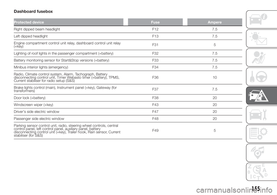
Dashboard fusebox
Protected device Fuse Ampere
Right dipped beam headlight F12 7.5
Left dipped headlight F13 7.5
Engine compartment control unit relay, dashboard control unit relay
(+key)F31 5
Lighting of roof lights in the passenger compartment (+battery) F32 7.5
Battery monitoring sensor for Start&Stop versions (+battery) F33 7.5
Minibus interior lights (emergency) F34 7.5
Radio, Climate control system, Alarm, Tachograph, Battery
disconnecting control unit, Timer Webasto timer (+battery), TPMS,
Current stabiliser for radio setup (S&S)F36 10
Brake lights control (main), Instrument panel (+key), Gateway (for
transformers)F37 7.5
Door lock (+battery) F38 20
Windscreen wiper (+key) F43 20
Driver's side electric window F47 20
Passenger side electric window F48 20
Parking sensor control unit, radio, steering wheel controls, central
control panel, left control panel, auxiliary panel, battery
disconnecting control unit (+key), Trailer hook, Rain sensor, Current
stabiliser (for S&S)F49 5
155
Page 170 of 296
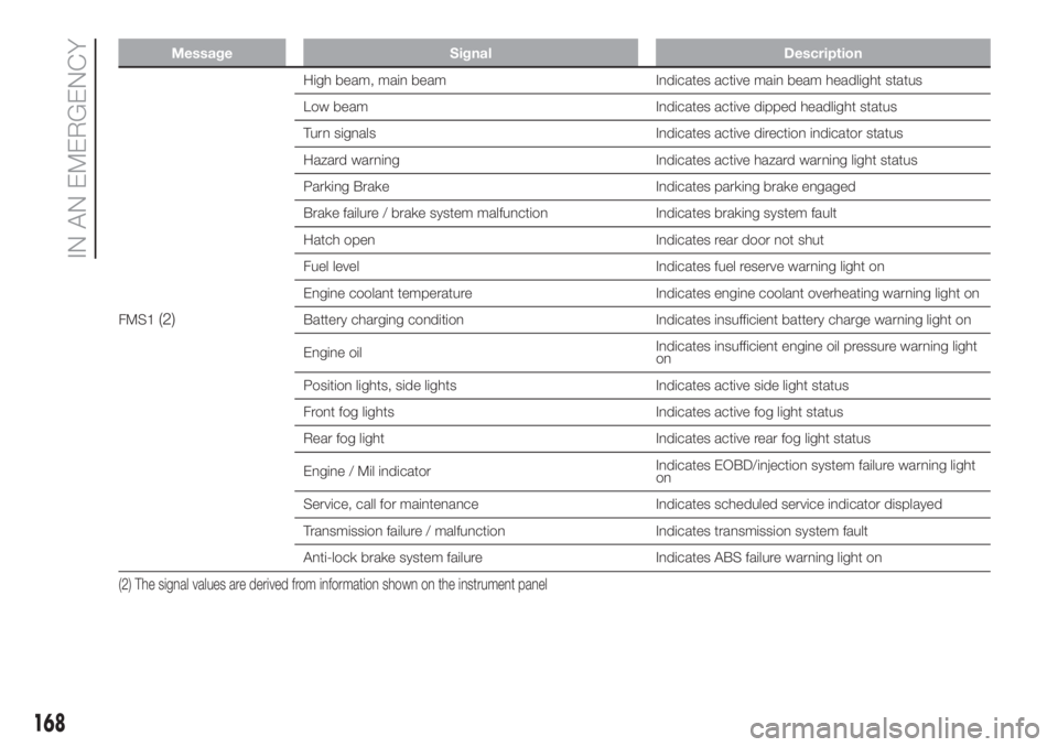
Message Signal Description
FMS1(2)
High beam, main beam Indicates active main beam headlight status
Low beam Indicates active dipped headlight status
Turn signals Indicates active direction indicator status
Hazard warning Indicates active hazard warning light status
Parking Brake Indicates parking brake engaged
Brake failure / brake system malfunction Indicates braking system fault
Hatch open Indicates rear door not shut
Fuel level Indicates fuel reserve warning light on
Engine coolant temperature Indicates engine coolant overheating warning light on
Battery charging condition Indicates insufficient battery charge warning light on
Engine oilIndicates insufficient engine oil pressure warning light
on
Position lights, side lights Indicates active side light status
Front fog lights Indicates active fog light status
Rear fog light Indicates active rear fog light status
Engine / Mil indicatorIndicates EOBD/injection system failure warning light
on
Service, call for maintenance Indicates scheduled service indicator displayed
Transmission failure / malfunction Indicates transmission system fault
Anti-lock brake system failure Indicates ABS failure warning light on
(2) The signal values are derived from information shown on the instrument panel
168
IN AN EMERGENCY
Page 171 of 296
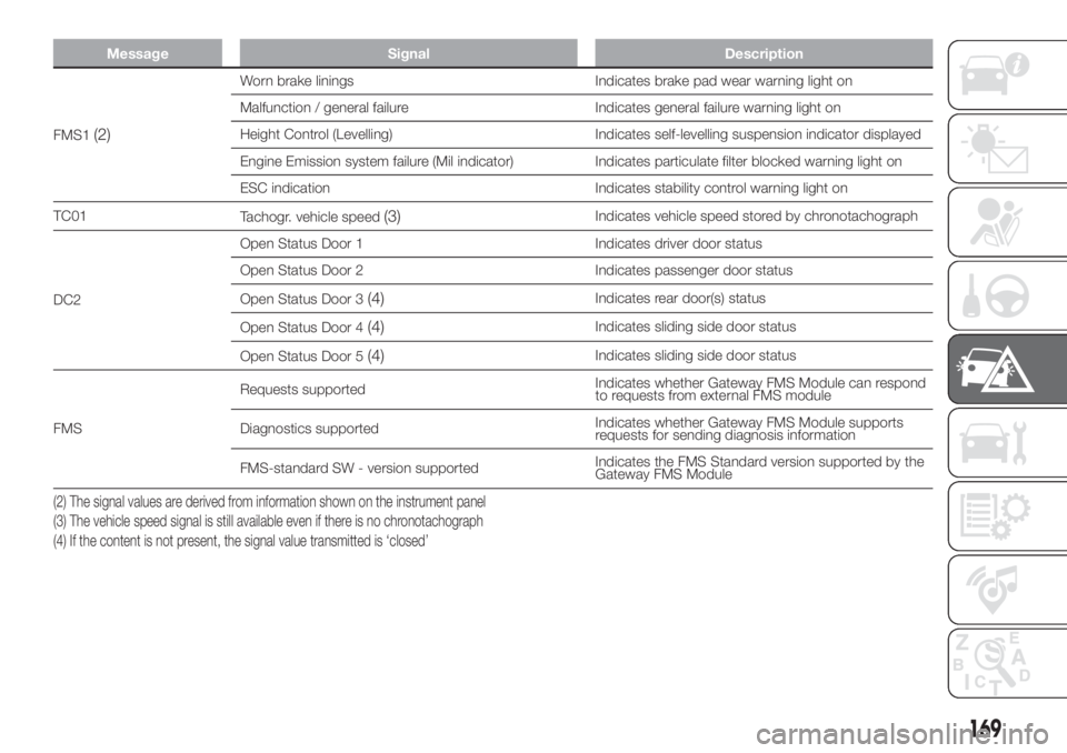
Message Signal Description
FMS1(2)
Worn brake linings Indicates brake pad wear warning light on
Malfunction / general failure Indicates general failure warning light on
Height Control (Levelling) Indicates self-levelling suspension indicator displayed
Engine Emission system failure (Mil indicator) Indicates particulate filter blocked warning light on
ESC indication Indicates stability control warning light on
TC01
Tachogr. vehicle speed
(3)Indicates vehicle speed stored by chronotachograph
DC2Open Status Door 1 Indicates driver door status
Open Status Door 2 Indicates passenger door status
Open Status Door 3
(4)Indicates rear door(s) status
Open Status Door 4
(4)Indicates sliding side door status
Open Status Door 5
(4)Indicates sliding side door status
FMSRequests supportedIndicates whether Gateway FMS Module can respond
to requests from external FMS module
Diagnostics supportedIndicates whether Gateway FMS Module supports
requests for sending diagnosis information
FMS-standard SW - version supportedIndicates the FMS Standard version supported by the
Gateway FMS Module
(2) The signal values are derived from information shown on the instrument panel
(3) The vehicle speed signal is still available even if there is no chronotachograph
(4) If the content is not present, the signal value transmitted is ‘closed’
169
Page 173 of 296
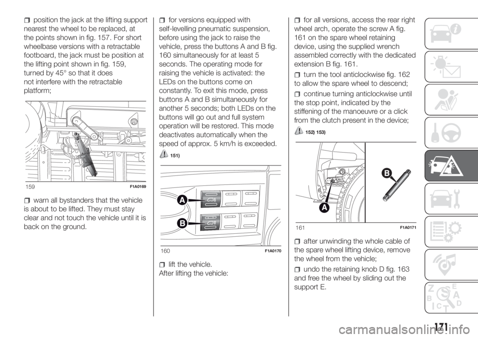
position the jack at the lifting support
nearest the wheel to be replaced, at
the points shown in fig. 157. For short
wheelbase versions with a retractable
footboard, the jack must be position at
the lifting point shown in fig. 159,
turned by 45° so that it does
not interfere with the retractable
platform;
warn all bystanders that the vehicle
is about to be lifted. They must stay
clear and not touch the vehicle until it is
back on the ground.
for versions equipped with
self-levelling pneumatic suspension,
before using the jack to raise the
vehicle, press the buttons A and B fig.
160 simultaneously for at least 5
seconds. The operating mode for
raising the vehicle is activated: the
LEDs on the buttons come on
constantly. To exit this mode, press
buttons A and B simultaneously for
another 5 seconds; both LEDs on the
buttons will go out and full system
operation will be restored. This mode
deactivates automatically when the
speed of approx. 5 km/h is exceeded.
151)
lift the vehicle.
After lifting the vehicle:
for all versions, access the rear right
wheel arch, operate the screw A fig.
161 on the spare wheel retaining
device, using the supplied wrench
assembled correctly with the dedicated
extension B fig. 161.
turn the tool anticlockwise fig. 162
to allow the spare wheel to descend;
continue turning anticlockwise until
the stop point, indicated by the
stiffening of the manoeuvre or a click
from the clutch present in the device;
152) 153)
after unwinding the whole cable of
the spare wheel lifting device, remove
the wheel from the vehicle;
undo the retaining knob D fig. 163
and free the wheel by sliding out the
support E.
159F1A0169
160F1A0170
161F1A0171
171
Page 174 of 296
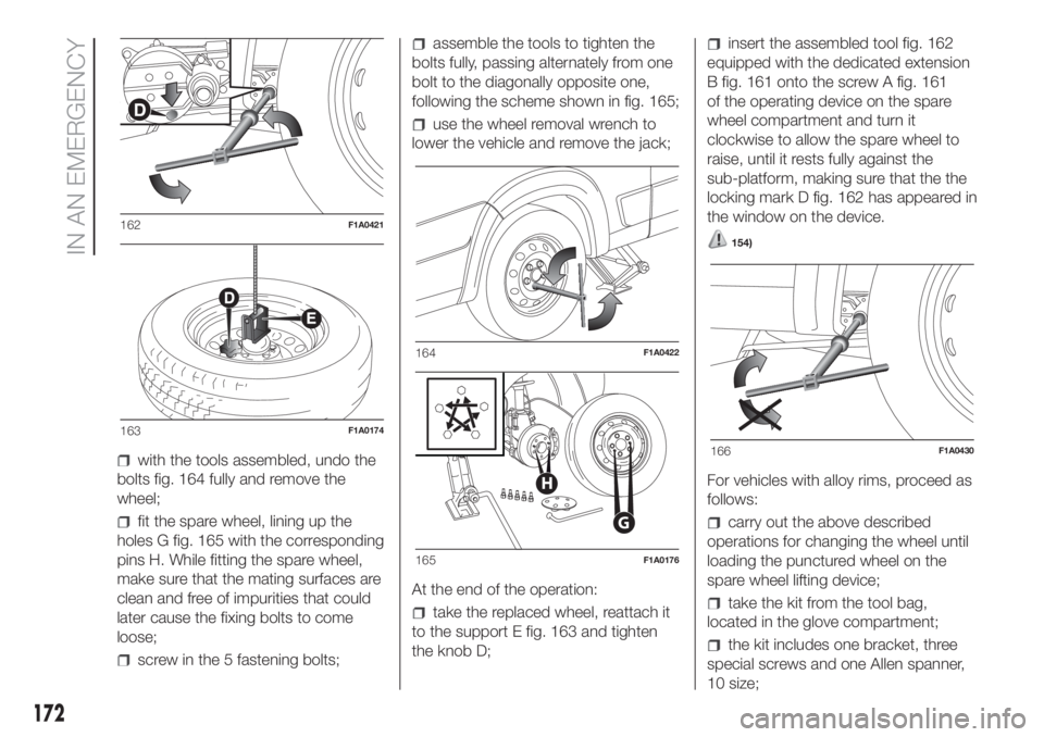
with the tools assembled, undo the
bolts fig. 164 fully and remove the
wheel;
fit the spare wheel, lining up the
holes G fig. 165 with the corresponding
pins H. While fitting the spare wheel,
make sure that the mating surfaces are
clean and free of impurities that could
later cause the fixing bolts to come
loose;
screw in the 5 fastening bolts;
assemble the tools to tighten the
bolts fully, passing alternately from one
bolt to the diagonally opposite one,
following the scheme shown in fig. 165;
use the wheel removal wrench to
lower the vehicle and remove the jack;
At the end of the operation:
take the replaced wheel, reattach it
to the support E fig. 163 and tighten
the knob D;
insert the assembled tool fig. 162
equipped with the dedicated extension
B fig. 161 onto the screw A fig. 161
of the operating device on the spare
wheel compartment and turn it
clockwise to allow the spare wheel to
raise, until it rests fully against the
sub-platform, making sure that the the
locking mark D fig. 162 has appeared in
the window on the device.
154)
For vehicles with alloy rims, proceed as
follows:
carry out the above described
operations for changing the wheel until
loading the punctured wheel on the
spare wheel lifting device;
take the kit from the tool bag,
located in the glove compartment;
the kit includes one bracket, three
special screws and one Allen spanner,
10 size;
162F1A0421
163F1A0174
164F1A0422
G
H
165F1A0176
166F1A0430
172
IN AN EMERGENCY
Page 175 of 296
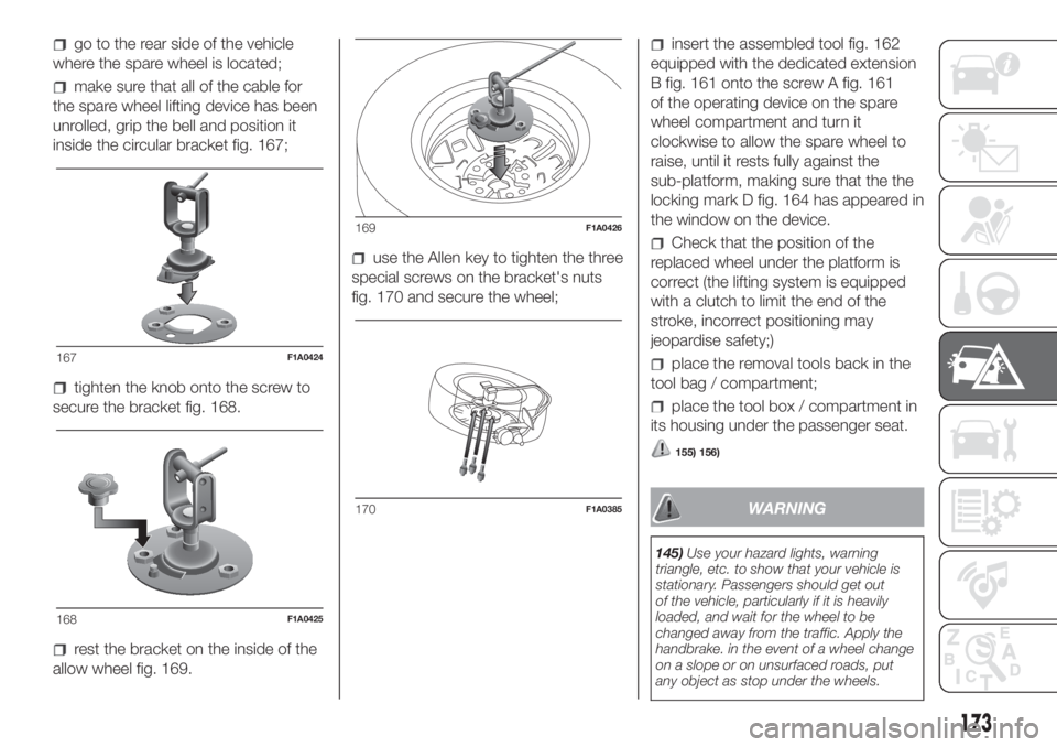
go to the rear side of the vehicle
where the spare wheel is located;
make sure that all of the cable for
the spare wheel lifting device has been
unrolled, grip the bell and position it
inside the circular bracket fig. 167;
tighten the knob onto the screw to
secure the bracket fig. 168.
rest the bracket on the inside of the
allow wheel fig. 169.
use the Allen key to tighten the three
special screws on the bracket's nuts
fig. 170 and secure the wheel;
insert the assembled tool fig. 162
equipped with the dedicated extension
B fig. 161 onto the screw A fig. 161
of the operating device on the spare
wheel compartment and turn it
clockwise to allow the spare wheel to
raise, until it rests fully against the
sub-platform, making sure that the the
locking mark D fig. 164 has appeared in
the window on the device.
Check that the position of the
replaced wheel under the platform is
correct (the lifting system is equipped
with a clutch to limit the end of the
stroke, incorrect positioning may
jeopardise safety;)
place the removal tools back in the
tool bag / compartment;
place the tool box / compartment in
its housing under the passenger seat.
155) 156)
WARNING
145)Use your hazard lights, warning
triangle, etc. to show that your vehicle is
stationary. Passengers should get out
of the vehicle, particularly if it is heavily
loaded, and wait for the wheel to be
changed away from the traffic. Apply the
handbrake. in the event of a wheel change
on a slope or on unsurfaced roads, put
any object as stop under the wheels.
167F1A0424
168F1A0425
169F1A0426
170F1A0385
173
Page 176 of 296
146)The spare wheel supplied (for
versions/markets, where provided) is
specific for your vehicle. Therefore, it must
not be used on other models. Do not
use spare wheels of other models on your
vehicle. The wheel bolts are specific for
your vehicle: do not use them on different
models and do not use bolts from other
models on your car.
147)Repair and refit the standard wheel as
soon as possible. Do not apply grease to
the bolt threads before fitting: they could
come unscrewed.
148)Use the jack only to replace wheels
on the vehicle with which it is supplied
or on other vehicles of the same model.
Never use the jack for other purposes,
such as lifting other vehicle models. Never
use the jack to carry out repairs under
the vehicle. Incorrect positioning of the jack
may cause the lifted vehicle to fall. Do not
use the jack for loads higher than the
one shown on its label.
149)Never tamper with the inflation valve.
Never introduce tools of any kind between
rim and tyre. Check tyre and spare wheel
pressure regularly, referring to the values
shown in the "Technical specifications"
section.
150)No tools other than the crank
provided should be used with the spare
wheel lifting device; it should be operated
by hand only.
151)On versions equipped with self-
levelling air suspension, never introduce the
head or hands in the wheel arch: the
vehicle could raise or lower automatically
depending on possible load or temperature
changes.152)The device should only be operated
by hand, without using any type of tool
other than the crank provided like
pneumatic or electrical screwers.
153)The moving components of the jack
(screws and joints) can also cause injuries:
avoid touching them. If you come into
contact with lubricating grease, clean
yourself thoroughly.
154)At the end of the operation of
raising/locking the spare wheel, after
checking that the wheel is positioned
correctly under the platform (yellow notch
inside the window on the device), extract
the operating wrench. Take care not to turn
the wrench in the wrong direction (as in
fig. 166) to facilitate extracting it, to prevent
the attachment device from being
released and to ensure that the wheel
assembly remains safely fastened.
155)Each time the spare wheel is moved,
check that it is correctly positioned in its
housing under the platform. If it is not
correctly positioned, this could adversely
affect safety.
156)The spare wheel lifting device is
equipped with a clutch safety system for its
own protection; this could activated if an
excessive load is applied on the
maneuvering screw.FIX & GO
AUTOMATIC QUICK
TYRE REPAIR KIT
(for versions/markets, where provided)
The Fix & Go automatic quick tyre
repair kit is located at the front of the
vehicle passenger compartment and
includes fig. 171:
bottle A containing sealer and fitted
with:
– a transparent filler pipe B;
– a black pressure restoring pipe E;
– sticker C bearing the notice “max. 80
km/h”, to be placed in a position visible
to the driver (on the instrument panel)
after fixing the tyre;
171F1A0180
174
IN AN EMERGENCY
Page 177 of 296
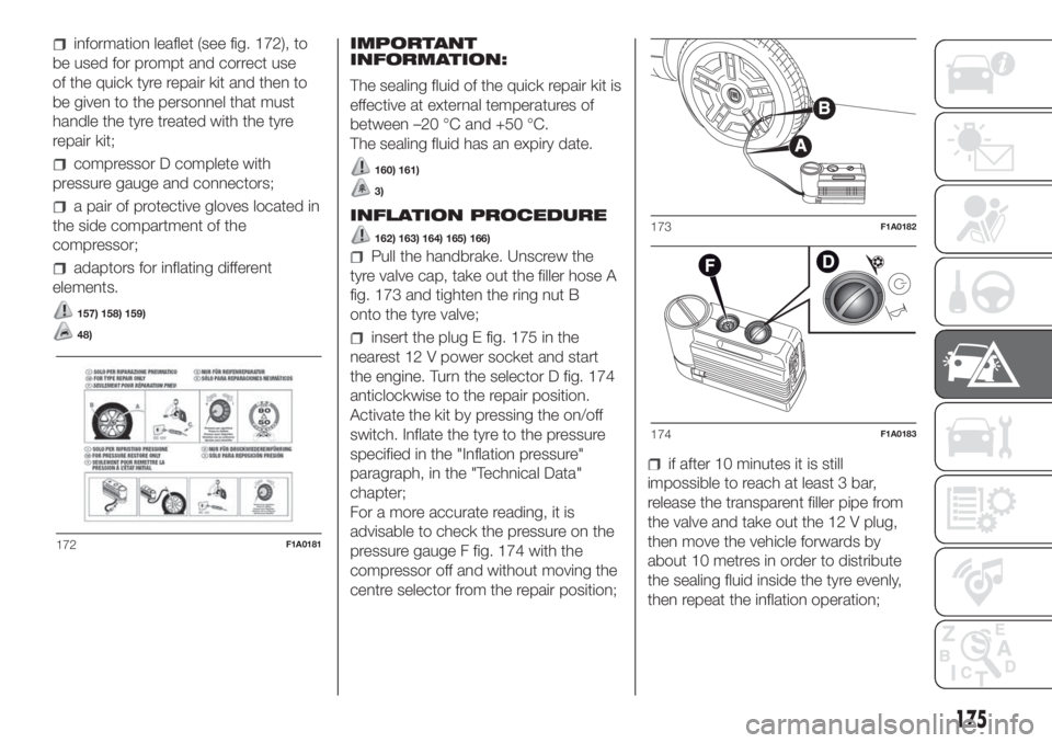
information leaflet (see fig. 172), to
be used for prompt and correct use
of the quick tyre repair kit and then to
be given to the personnel that must
handle the tyre treated with the tyre
repair kit;
compressor D complete with
pressure gauge and connectors;
a pair of protective gloves located in
the side compartment of the
compressor;
adaptors for inflating different
elements.
157) 158) 159)
48)
IMPORTANT
INFORMATION:
The sealing fluid of the quick repair kit is
effective at external temperatures of
between –20 °C and +50 °C.
The sealing fluid has an expiry date.
160) 161)
3)
INFLATION PROCEDURE
162) 163) 164) 165) 166)
Pull the handbrake. Unscrew the
tyre valve cap, take out the filler hose A
fig. 173 and tighten the ring nut B
onto the tyre valve;
insert the plug E fig. 175 in the
nearest 12 V power socket and start
the engine. Turn the selector D fig. 174
anticlockwise to the repair position.
Activate the kit by pressing the on/off
switch. Inflate the tyre to the pressure
specified in the "Inflation pressure"
paragraph, in the "Technical Data"
chapter;
For a more accurate reading, it is
advisable to check the pressure on the
pressure gauge F fig. 174 with the
compressor off and without moving the
centre selector from the repair position;
if after 10 minutes it is still
impossible to reach at least 3 bar,
release the transparent filler pipe from
the valve and take out the 12 V plug,
then move the vehicle forwards by
about 10 metres in order to distribute
the sealing fluid inside the tyre evenly,
then repeat the inflation operation;
172F1A0181
173F1A0182
174F1A0183
175
Page 182 of 296
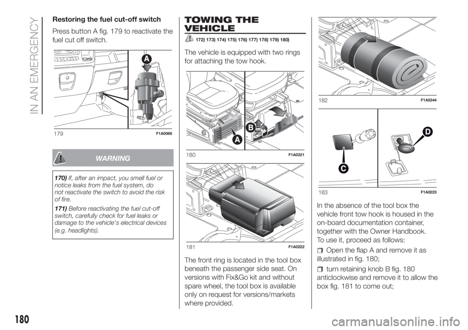
Restoring the fuel cut-off switch
Press button A fig. 179 to reactivate the
fuel cut off switch.
WARNING
170)If, after an impact, you smell fuel or
notice leaks from the fuel system, do
not reactivate the switch to avoid the risk
of fire.
171)Before reactivating the fuel cut-off
switch, carefully check for fuel leaks or
damage to the vehicle's electrical devices
(e.g. headlights).
TOWING THE
VEHICLE
172) 173) 174) 175) 176) 177) 178) 179) 180)
The vehicle is equipped with two rings
for attaching the tow hook.
The front ring is located in the tool box
beneath the passenger side seat. On
versions with Fix&Go kit and without
spare wheel, the tool box is available
only on request for versions/markets
where provided.In the absence of the tool box the
vehicle front tow hook is housed in the
on-board documentation container,
together with the Owner Handbook.
To use it, proceed as follows:
Open the flap A and remove it as
illustrated in fig. 180;
turn retaining knob B fig. 180
anticlockwise and remove it to allow the
box fig. 181 to come out;
179F1A0086
180F1A0221
181F1A0222
182F1A0344
183F1A0223
180
IN AN EMERGENCY
Page 183 of 296
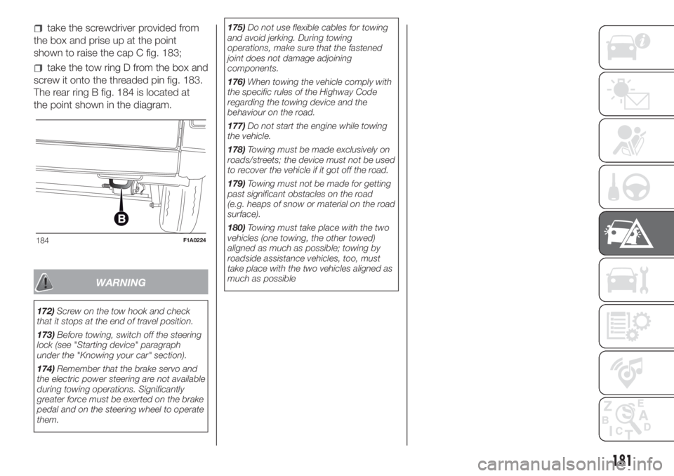
take the screwdriver provided from
the box and prise up at the point
shown to raise the cap C fig. 183;
take the tow ring D from the box and
screw it onto the threaded pin fig. 183.
The rear ring B fig. 184 is located at
the point shown in the diagram.
WARNING
172)Screw on the tow hook and check
that it stops at the end of travel position.
173)Before towing, switch off the steering
lock (see "Starting device" paragraph
under the "Knowing your car" section).
174)Remember that the brake servo and
the electric power steering are not available
during towing operations. Significantly
greater force must be exerted on the brake
pedal and on the steering wheel to operate
them.175)Do not use flexible cables for towing
and avoid jerking. During towing
operations, make sure that the fastened
joint does not damage adjoining
components.
176)When towing the vehicle comply with
the specific rules of the Highway Code
regarding the towing device and the
behaviour on the road.
177)Do not start the engine while towing
the vehicle.
178)Towing must be made exclusively on
roads/streets; the device must not be used
to recover the vehicle if it got off the road.
179)Towing must not be made for getting
past significant obstacles on the road
(e.g. heaps of snow or material on the road
surface).
180)Towing must take place with the two
vehicles (one towing, the other towed)
aligned as much as possible; towing by
roadside assistance vehicles, too, must
take place with the two vehicles aligned as
much as possible
184F1A0224
181