fuse FIAT DUCATO BASE CAMPER 2017 Owner handbook (in English)
[x] Cancel search | Manufacturer: FIAT, Model Year: 2017, Model line: DUCATO BASE CAMPER, Model: FIAT DUCATO BASE CAMPER 2017Pages: 296, PDF Size: 14.44 MB
Page 13 of 296
5)Under no circumstances should
aftermarket operations be carried out
involving steering system or steering
column modifications (e.g. installation of
anti-theft device). This could negatively
affect performance and safety, invalidate
the warranty, cause serious safety
problems and also result in vehicle
non-compliance with type-approval
requirements.ELECTRONIC ALARM
(for versions/markets, where provided)
The alarm, in addition to all the remote
control functions described previously,
is controlled by the receiver located
under the dashboard near the fuse box.
Activation
With the doors and bonnet closed and
the ignition key either turned to STOP
or removed, point the key with the
remote control towards the vehicle and
press and release the lock button.
Excluding some markets, the system
produces an acoustic signal (beep) and
enables door locking.
The switching on of the alarm is
preceded by an self-diagnosis stage: if
a fault is detected, the system
produces another acoustic signal.
In this case, turn the alarm off by
pressing the "release doors/release
load compartment" button, check that
the doors and bonnet are properly
closed and turn the alarm back on by
pressing the lock button.
If a door or the bonnet is not properly
shut, it will be excluded from the testing
by the alarm system.If the alarm produces an acoustic signal
even when the doors and bonnet are
correctly closed, a fault has occurred in
the operation of the system. Contact
a Fiat Dealership.
IMPORTANT The alarm does not come
on when the central locking is activated
using the metal insert in the key.
IMPORTANT The alarm is adapted to
meet requirements in various countries.
Turning off
Press the door release/load
compartment release button on the key
with remote control.
The following operations are performed
(excluding some markets):
direction indicators flash twice;
there are two short acoustic signals
(beeps);
doors are unlocked.
IMPORTANT The alarm does not switch
off when the central opening is
activated using the metal insert in the
key.
11
Page 15 of 296
Turn the metal insert anticlockwise fig. 6
in the driver's side door lock to unlock
all the doors. With the battery
disconnected, access to the vehicle will
only be possible by unlocking the
driver's door using the mechanical lock.
Locking/unlocking doors from the
inside
Press the button A fig. 7 to lock the
doors and press it again to unlock
them. Locking / unlocking is centralized
(front and rear).
When the doors are locked, the LED in
button A is on and, when the button
is pressed again, all the doors are
centrally unlocked and the warning light
is switched off.
When the doors are unlocked, the LED
is off and pressing the button again
centrally locks all the doors. The doors
will be locked only if all the doors are
properly shut.Following the locking of the doors
using:
remote control
door pawl
it will not be possible to unlock using
the button A fig. 7 on the dashboard.
IMPORTANT With the central locking
on, pulling the opening lever for one of
the front doors causes the central
locking to be switched off. Individual
doors can be unlocked by pulling
the opening handle of one of the rear
doors.
If a power supply is not present (blown
fuse, battery disconnected, etc.) it is,
however, possible to lock the doors
manually.
After exceeding 20 km/h, all the doors
will be locked automatically if the setup
menu function has been selected
(see “Multifunction display” paragraph
in this section).
LOCKING/UNLOCKING
THE LOAD
COMPARTMENT
The activation of the locking is signalled
by the LED in the button.
The LED comes on in the following
cases:
after each door lock command from
the D fig. 8 or
button on the
dashboard;
when the instrument panel is
activated;
upon opening of one of the front
doors;
when the door is locked at 20 km/h
(if activated from the menu).
The lock is turned off when one of the
load compartment doors is opened
or on a door release request (load
compartment or centralised) or
an unlocking request from the remote
control/door catch.
DEAD LOCK DEVICE
(for versions/markets, where provided)
It is a safety device that disables
operation of the interior handles.
Operate the lock/unlock button A fig. 7
to prevent opening the doors from
inside the passenger compartment in
the event of an attempted break-in (e.g.
when a window is broken).
7F1A0303
8F1A0116
13
Page 36 of 296
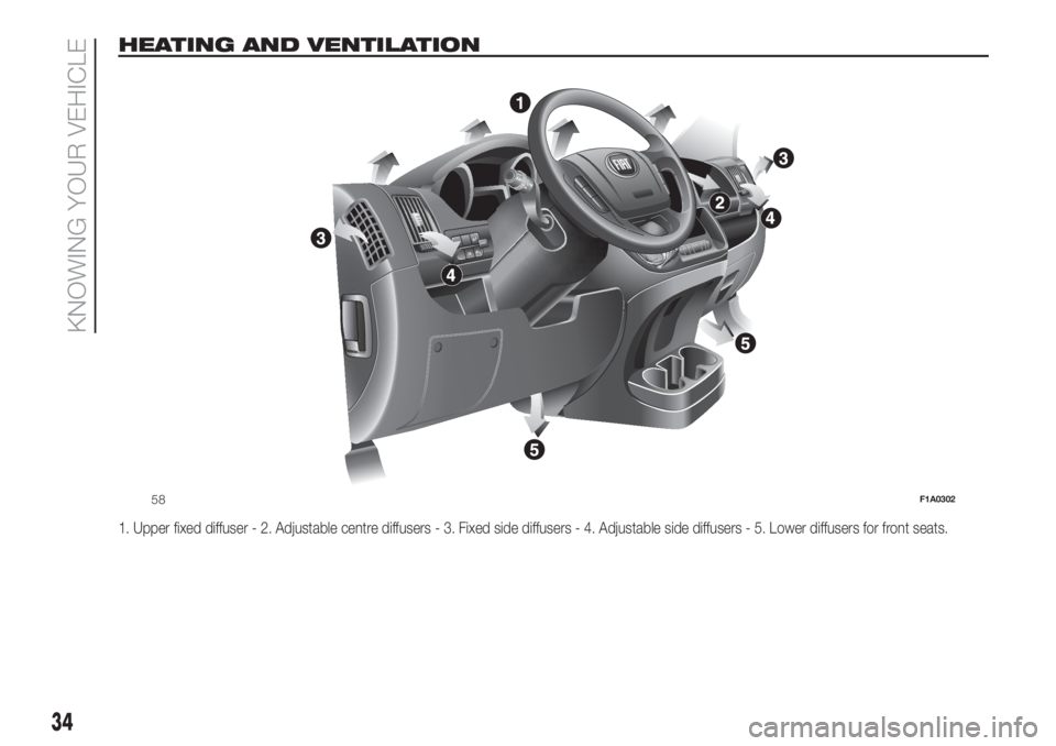
HEATING AND VENTILATION
1. Upper fixed diffuser - 2. Adjustable centre diffusers - 3. Fixed side diffusers - 4. Adjustable side diffusers - 5. Lower diffusers for front seats.
MODE
58F1A0302
34
KNOWING YOUR VEHICLE
Page 69 of 296
What it means What to do
amberGENERAL FAILURE WARNING
(Versions with multifunction display)
The warning light turns on in the following
circumstances:
If the fuel inertia cut-off switch is activated
Light failure (rear fog lamps, direction indicators,
brake lights, number plate lights, side lights, daytime
running lights, main beam automatism, trailer direction
indicators, trailer side lights)The failure relating to these lights could be: one or
more blown bulbs, a blown protection fuse or a break
in the electrical connection.
Airbag warning light failure (generic failure warning
light flashing)In this case, the warning light may not indicate
problems with the restraint systems. Before
continuing, contact a Fiat Dealership to have the
system checked immediately.
Rain sensor failure
Diesel filter sensor failure
Trailer connection failure
Audio system failure
Engine oil pressure sensor failure
Parking sensor failure
Water in diesel fuel filterGo to a Fiat Dealership to have the fault fixed as soon
as possible.
67
Page 76 of 296
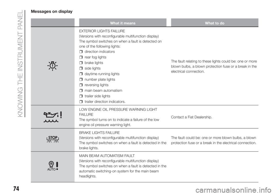
Messages on display
What it means What to do
EXTERIOR LIGHTS FAILURE
(Versions with reconfigurable multifunction display)
The symbol switches on when a fault is detected on
one of the following lights:
direction indicators
rear fog lights
brake lights
side lights
daytime running lights
number plate lights
reversing lights
main beam automatism
trailer side lights
trailer direction indicators.The fault relating to these lights could be: one or more
blown bulbs, a blown protection fuse or a break in the
electrical connection.
LOW ENGINE OIL PRESSURE WARNING LIGHT
FAILURE
The symbol turns on to indicate a failure of the low
engine oil pressure warning light.Contact a Fiat Dealership.
BRAKE LIGHTS FAILURE
(Versions with reconfigurable multifunction display)
The symbol switches on when a fault is detected in the
brake lights.The fault could be: one or more blown bulbs, a blown
protection fuse or a break in the electrical connection.
MAIN BEAM AUTOMATISM FAULT
(Versions with reconfigurable multifunction display)
The symbol switches on when a fault is detected in the
automatic switching-on system for the main beam
headlights.
74
KNOWING THE INSTRUMENT PANEL
Page 123 of 296
When the device is active, the vehicle
speed depends on the accelerator
pedal, until the programmed speed limit
is reached (see "Speed limit
programming" paragraph).
If necessary (in the event of overtaking
for example), the set speed limit can
be exceeded by fully depressing the
accelerator pedal.
By gradually reducing the pressure on
the accelerator pedal, the function
will be reactivated as soon as the
vehicle speed drops below the
programmed speed.
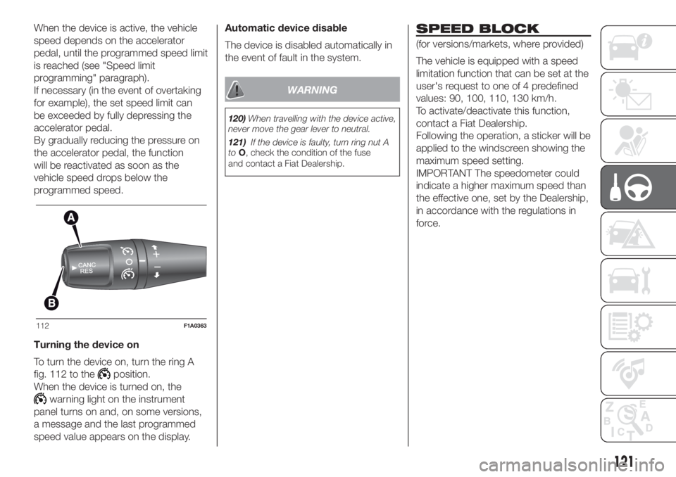
Turning the device on
To turn the device on, turn the ring A
fig. 112 to the
position.
When the device is turned on, the
warning light on the instrument
panel turns on and, on some versions,
a message and the last programmed
speed value appears on the display.Automatic device disable
The device is disabled automatically in
the event of fault in the system.
WARNING
120)When travelling with the device active,
never move the gear lever to neutral.
121)If the device is faulty, turn ring nut A
toO, check the condition of the fuse
and contact a Fiat Dealership.
SPEED BLOCK
(for versions/markets, where provided)
The vehicle is equipped with a speed
limitation function that can be set at the
user's request to one of 4 predefined
values: 90, 100, 110, 130 km/h.
To activate/deactivate this function,
contact a Fiat Dealership.
Following the operation, a sticker will be
applied to the windscreen showing the
maximum speed setting.
IMPORTANT The speedometer could
indicate a higher maximum speed than
the effective one, set by the Dealership,
in accordance with the regulations in
force.
112F1A0363
121
Page 144 of 296
IN AN EMERGENCY
A punctured tyre or a burnt-out bulb?
At times, a problem may interfere
with our journey.
The pages on emergencies can help
you to deal with critical situations
independently and with calm.
In an emergency we recommend that
you call the freephone number found in
the Warranty Booklet.
It is also possible to call the 00 800
3428 0000 freephone number to
search the nearest Fiat Dealership.REPLACING A BULB ......................143
REPLACING AN EXTERIOR BULB ..146
REPLACING INTERIOR BULBS ......151
REPLACING FUSES........................151
GATEWAY FMS MODULE ...............165
CHANGING A WHEEL ....................170
FIX & GO AUTOMATIC QUICK
TYRE REPAIR KIT ...........................174
JUMP STARTING ............................177
RECHARGING THE BATTERY ........178
FUEL CUT-OFF SWITCH ................179
TOWING THE VEHICLE ..................180
142
IN AN EMERGENCY
Page 145 of 296
REPLACING A BULB
GENERAL
INSTRUCTIONS
139) 140)
46)
When a light is not working, check
that the corresponding fuse is intact
before changing a bulb. For the location
of fuses, refer to the paragraph
"Replacing fuses" in this chapter.
before changing a bulb check the
contacts for oxidation;
burnt bulbs must be replaced by
others of the same type and power;
always check the headlight beam
direction after changing a bulb;
IMPORTANT A slight misting may
appear on the internal surface of the
headlight: this does not indicate a fault
and is caused by low temperature
and the degree of humidity in the air.
Misting will rapidly disappear when the
headlights are switched on. The
presence of drops inside the headlights
indicates infiltration of water. Contact
a Fiat Dealership.
WARNING
139)Modifications or repairs to the
electric system that are not carried out
properly or do not take the system
technical specifications into account can
cause malfunctions leading to the risk
of fire.
140)Halogen bulbs contain pressurised
gas, in the case of breakage they may
burst causing glass fragments to be
projected outwards.
WARNING
46)Halogen bulbs must be handled
holding the metallic part only. Touching the
transparent part of the bulb with your
fingers may reduce the intensity of the
emitted light and even reduce the lifespan
of the bulb. In the event of accidental
contact, wipe the bulb with a cloth
moistened with alcohol and let the bulb
dry.
143
Page 153 of 296
REPLACING
INTERIOR BULBS
For the type of bulb and relevant power
rating, see “Changing a bulb”.
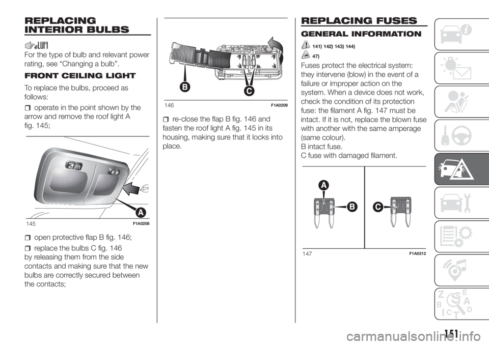
FRONT CEILING LIGHT
To replace the bulbs, proceed as
follows:
operate in the point shown by the
arrow and remove the roof light A
fig. 145;
open protective flap B fig. 146;
replace the bulbs C fig. 146
by releasing them from the side
contacts and making sure that the new
bulbs are correctly secured between
the contacts;
re-close the flap B fig. 146 and
fasten the roof light A fig. 145 in its
housing, making sure that it locks into
place.
REPLACING FUSES
GENERAL INFORMATION
141) 142) 143) 144)
47)
Fuses protect the electrical system:
they intervene (blow) in the event of a
failure or improper action on the
system. When a device does not work,
check the condition of its protection
fuse: the filament A fig. 147 must be
intact. If it is not, replace the blown fuse
with another with the same amperage
(same colour).
B intact fuse.
C fuse with damaged filament.
145F1A0208
146F1A0209
147F1A0212
151
Page 154 of 296
FUSE LOCATION
The vehicle fuses are grouped in three
control units located on the dashboard,
passenger compartment right pillar
and engine compartment.
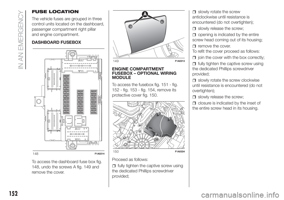
DASHBOARD FUSEBOX
To access the dashboard fuse box fig.
148, undo the screws A fig. 149 and
remove the cover.ENGINE COMPARTMENT
FUSEBOX – OPTIONAL WIRING
MODULE
To access the fusebox fig. 151 - fig.
152 - fig. 153 - fig. 154, remove its
protective cover fig. 150.
Proceed as follows:
fully tighten the captive screw using
the dedicated Phillips screwdriver
provided;
slowly rotate the screw
anticlockwise until resistance is
encountered (do not overtighten);
slowly release the screw;
opening is indicated by the entire
screw head coming out of its housing;
remove the cover.
To refit the cover proceed as follows:
join the cover with the box correctly;
fully tighten the captive screw using
the dedicated Phillips screwdriver
provided;
slowly rotate the screw clockwise
until resistance is encountered (do not
overtighten);
slowly release the screw;
closure is indicated by the inset of
the entire screw head in its housing.
148F1A0214
149F1A0213
150F1A0334
152
IN AN EMERGENCY