mirror FIAT DUCATO BASE CAMPER 2017 Owner handbook (in English)
[x] Cancel search | Manufacturer: FIAT, Model Year: 2017, Model line: DUCATO BASE CAMPER, Model: FIAT DUCATO BASE CAMPER 2017Pages: 296, PDF Size: 14.44 MB
Page 5 of 296
USE OF THE OWNER HANDBOOK
OPERATING INSTRUCTIONS
Each time direction instructions (left/right or forwards/backwards) about the vehicle are given, these must be intended as
regarding an occupant in the driver's seat. Special cases not complying with this rule will be specified as appropriate in the text.
The figures in the Owner Handbook are provided by way of example only: this might imply that some details of the image do
not correspond to the actual arrangement of your vehicle. In addition, the Handbook has been conceived considering vehicles
with steering wheel on the left side; it is therefore possible that on vehicles with steering wheel on the right side, the position
or construction of some controls is not exactly mirror-like with respect to the figure.
To identify the chapter with the information needed you can consult the index at the end of this Owner Handbook.
Chapters can be rapidly identified with dedicated graphic tabs, at the side of each odd page. A few pages further there is a key
for getting to know the chapter order and the relevant symbols in the tabs. There is in any case a textual indication of the
current chapter at the side of each even page.
WARNINGS AND PRECAUTIONS
While reading this Owner Handbook you will find a series ofWARNINGSto prevent procedures that could damage your
vehicle.
There are alsoPRECAUTIONSthat must be carefully followed to prevent incorrect use of the components of the vehicle,
which could cause accidents or injuries.
Therefore allWARNINGSandPRECAUTIONSmust always be carefully followed.
WARNINGSandPRECAUTIONSare recalled in the text with the following symbols:
personal safety;
vehicle integrity;
environmental protection.
NOTE These symbols, when necessary, are indicated besides the title or at the end of the line and are followed by a number.
That number recalls the corresponding warning at the end of the relevant section.
Page 9 of 296
KNOWING YOUR VEHICLE
In-depth knowledge of your new vehicle
starts here.
The booklet that you are reading simply
and directly explains how it is made
and how it works.
That’s why we advise you to read it
seated comfortably on board, so that
you can see what is described here for
yourself.SYMBOLS ...................................... 8
THE FIAT CODE SYSTEM ............... 8
THE KEYS....................................... 9
IGNITION SWITCH .......................... 10
ELECTRONIC ALARM..................... 11
DOORS ........................................... 12
SEATS ............................................ 16
STEERING WHEEL ......................... 21
REAR VIEW MIRRORS .................... 22
EXTERNAL LIGHTS......................... 24
HEADLIGHTS.................................. 27
ROOF LIGHTS ................................ 28
CONTROLS .................................... 29
WINDOW WASHING ....................... 32
HEATING AND VENTILATION.......... 34
HEATING AND VENTILATION
CONTROLS .................................... 35
MANUAL CLIMATE CONTROL
SYSTEM ......................................... 35
AUTOMATIC CLIMATE CONTROL
SYSTEM ......................................... 36
ADDITIONAL HEATER ..................... 37
INDEPENDENT ADDITIONAL
HEATER .......................................... 38
ELECTRIC WINDOWS .................... 41
BONNET ......................................... 42
HEAD RESTRAINTS ........................ 43
INTERIOR FITTINGS ...................... 44TACHOGRAPH ............................... 45
SELF-LEVELLING AIR
SUSPENSION ................................. 45
7
Page 24 of 296
WARNING
26)Any steering wheel position adjustment
should only be carried out with the vehicle
stationary and the engine turned off.
27)It is absolutely forbidden to carry out
any after-market operation involving
steering system or steering column
modifications (e.g.: installation of anti-theft
device). This could badly affect
performance and safety, invalidate the
warranty and also result in the non-
compliance of the vehicle with approval
requirements.
REAR VIEW
MIRRORS
INTERIOR MIRROR
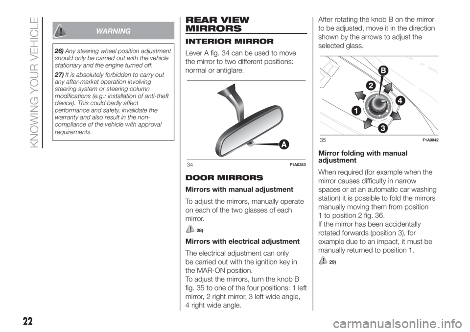
Lever A fig. 34 can be used to move
the mirror to two different positions:
normal or antiglare.
DOOR MIRRORS
Mirrors with manual adjustment
To adjust the mirrors, manually operate
on each of the two glasses of each
mirror.
28)
Mirrors with electrical adjustment
The electrical adjustment can only
be carried out with the ignition key in
the MAR-ON position.
To adjust the mirrors, turn the knob B
fig. 35 to one of the four positions: 1 left
mirror, 2 right mirror, 3 left wide angle,
4 right wide angle.After rotating the knob B on the mirror
to be adjusted, move it in the direction
shown by the arrows to adjust the
selected glass.
Mirror folding with manual
adjustment
When required (for example when the
mirror causes difficulty in narrow
spaces or at an automatic car washing
station) it is possible to fold the mirrors
manually moving them from position
1 to position 2 fig. 36.
If the mirror has been accidentally
rotated forwards (position 3), for
example due to an impact, it must be
manually returned to position 1.
29)
34F1A0353
35F1A0042
22
KNOWING YOUR VEHICLE
Page 25 of 296
Mirror folding with electrical
adjustment
(for versions/markets, where provided)
When required (for example when
the mirror causes difficulty in narrow
spaces or during an automatic car
wash) it is possible to fold the mirrors
both electrically and manually, moving
them from position 1 to position 2
fig. 36.Electric folding
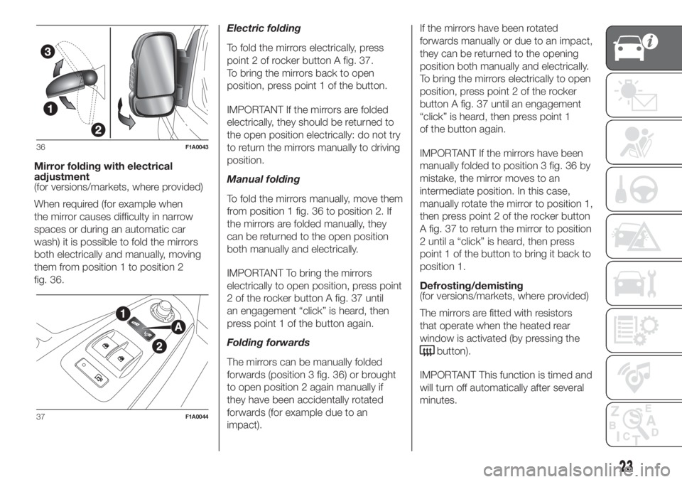
To fold the mirrors electrically, press
point 2 of rocker button A fig. 37.
To bring the mirrors back to open
position, press point 1 of the button.
IMPORTANT If the mirrors are folded
electrically, they should be returned to
the open position electrically: do not try
to return the mirrors manually to driving
position.
Manual folding
To fold the mirrors manually, move them
from position 1 fig. 36 to position 2. If
the mirrors are folded manually, they
can be returned to the open position
both manually and electrically.
IMPORTANT To bring the mirrors
electrically to open position, press point
2 of the rocker button A fig. 37 until
an engagement “click” is heard, then
press point 1 of the button again.
Folding forwards
The mirrors can be manually folded
forwards (position 3 fig. 36) or brought
to open position 2 again manually if
they have been accidentally rotated
forwards (for example due to an
impact).If the mirrors have been rotated
forwards manually or due to an impact,
they can be returned to the opening
position both manually and electrically.
To bring the mirrors electrically to open
position, press point 2 of the rocker
button A fig. 37 until an engagement
“click” is heard, then press point 1
of the button again.
IMPORTANT If the mirrors have been
manually folded to position 3 fig. 36 by
mistake, the mirror moves to an
intermediate position. In this case,
manually rotate the mirror to position 1,
then press point 2 of the rocker button
A fig. 37 to return the mirror to position
2 until a “click” is heard, then press
point 1 of the button to bring it back to
position 1.
Defrosting/demisting
(for versions/markets, where provided)
The mirrors are fitted with resistors
that operate when the heated rear
window is activated (by pressing the
button).
IMPORTANT This function is timed and
will turn off automatically after several
minutes.
36F1A0043
37F1A0044
23
Page 26 of 296
WARNING
28)As the driver's exterior mirror is curved,
it may slightly alter the perception of
distance of the reflected image. Further,
the reflective surface of the lower part
of the exterior mirrors is parabolic to
increase the field of view. The reflected
image size is thus reduced and gives the
impression that the reflected item is further
away than it actually is.
29)When driving the mirrors should always
remain in position 1.
EXTERNAL LIGHTS
IN BRIEF
The left stalk includes the controls for
the exterior lights.
The exterior lights can only be
switched on when the ignition key is
in the ON position.
LIGHTS OFF
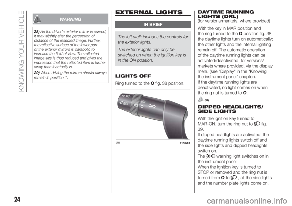
Ring turned to theOfig. 38 position.DAYTIME RUNNING
LIGHTS (DRL)
(for versions/markets, where provided)
With the key in MAR position and
the ring turned to theOposition fig. 38,
the daytime lights turn on automatically;
the other lights and the internal lighting
remain off. The automatic operation
of the daytime running lights can be
activated/deactivated, for versions/
markets where provided, via the display
menu (see "Display" in the "Knowing
the instrument panel" chapter).
If the daytime running lights are
deactivated, no light comes on when
the ring nut is turned toO.
30)
DIPPED HEADLIGHTS/
SIDE LIGHTS
With the ignition key turned to
MAR-ON, turn the ring nut to
fig.
39.
If dipped headlights are activated, the
daytime running lights switch off and
the side lights and dipped headlights
switch on.
The
warning light switches on in
the instrument panel.
When the ignition key is turned to
STOP or removed and the ring nut is
turned fromOto
, all the side lights
and the number plate lights come on.
38F1A0064
24
KNOWING YOUR VEHICLE
Page 34 of 296
WINDOW WASHING
IN BRIEF
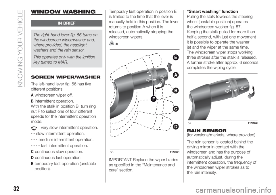
The right-hand lever fig. 56 turns on
the windscreen wiper/washer and,
where provided, the headlight
washers and the rain sensor.
This operates only with the ignition
key turned to MAR.
SCREEN WIPER/WASHER
The left-hand lever fig. 56 has five
different positions:
Awindscreen wiper off.
Bintermittent operation.
With the stalk in position B, turn ring
nut F to select one of four different
speeds for the intermittent operation
mode:
very slow intermittent operation.
--slow intermittent operation.
---medium intermittent operation.
----fast intermittent operation.
Ccontinuous slow operation.
Dcontinuous fast operation
Etemporary fast operation (unstable
position).Temporary fast operation in position E
is limited to the time that the lever is
manually held in this position. The lever
returns to position A when it is
released, automatically stopping the
windscreen wipers.
4)
IMPORTANT Replace the wiper blades
as specified in the “Maintenance and
care” section.“Smart washing” function
Pulling the stalk towards the steering
wheel (unstable position) operates
the windscreen washer fig. 57.
Keeping the stalk pulled for more than
half a second, with just one movement
it is possible to operate the washer
jet and the wiper at the same time.
The windscreen wiper stops working
three strokes after the stalk is released.
A further stroke after approx. 6 seconds
completes the wiping cycle.
RAIN SENSOR
(for versions/markets, where provided)
The rain sensor is located behind the
driving mirror in contact with the
windscreen and has the purpose of
automatically adjust, during the
intermittent operation, the frequency of
the windscreen wiper strokes as to
the rain intensity.
56F1A0071
57F1A0072
32
KNOWING YOUR VEHICLE
Page 38 of 296
Air distribution ring nut C
to convey air to the central and
side vents;
to warm the feet and convey
slightly cooler air to the dashboard
vents, in intermediate temperature
conditions;
for heating when the outside
temperature is very low: to direct
as much air as possible to the
feet;
to warm the feet and demist the
windscreen at the same time;
for quick windscreen demisting.
Air recirculation on/off knob D
Press the button (button LED on) to
turn the internal air recirculation on.
Press the button again (button LED off)
to turn the internal air recirculation off.
Climate control system on/off
button E
Press the button (button LED on) to
turn the climate control system on.
Press the button again (button LED off)
to turn the climate control system off.
AUTOMATIC
CLIMATE CONTROL
SYSTEM
2)
(for versions/markets, where provided)
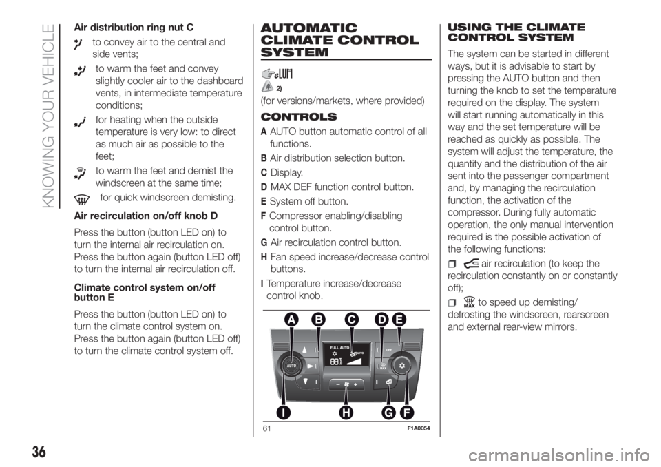
CONTROLS
AAUTO button automatic control of all
functions.
BAir distribution selection button.
CDisplay.
DMAX DEF function control button.
ESystem off button.
FCompressor enabling/disabling
control button.
GAir recirculation control button.
HFan speed increase/decrease control
buttons.
ITemperature increase/decrease
control knob.USING THE CLIMATE
CONTROL SYSTEM
The system can be started in different
ways, but it is advisable to start by
pressing the AUTO button and then
turning the knob to set the temperature
required on the display. The system
will start running automatically in this
way and the set temperature will be
reached as quickly as possible. The
system will adjust the temperature, the
quantity and the distribution of the air
sent into the passenger compartment
and, by managing the recirculation
function, the activation of the
compressor. During fully automatic
operation, the only manual intervention
required is the possible activation of
the following functions:
air recirculation (to keep the
recirculation constantly on or constantly
off);
to speed up demisting/
defrosting the windscreen, rearscreen
and external rear-view mirrors.
61F1A0054
36
KNOWING YOUR VEHICLE
Page 91 of 296
DRIVING ADVISOR
(lane crossing warning)
(for versions/markets, where provided)
77) 78) 79)The Driving Advisor is a warning system
that notifies the driver if he/she crosses
the lane because he/she has been
distracted.
A video sensor, fitted on the windscreen
near the interior rear view mirror,
detects the lane demarcation lines and
the position of the vehicle in relation
to them.
IMPORTANT On cars with Driving
Advisor, it is advisable to contact a Fiat
Dealership should the windscreen
need to be replaced. If the repair is
carried out at a specialist window
replacement centre, it is still necessary
to go to a Fiat Dealership to have the
camera calibrated.
OPERATION
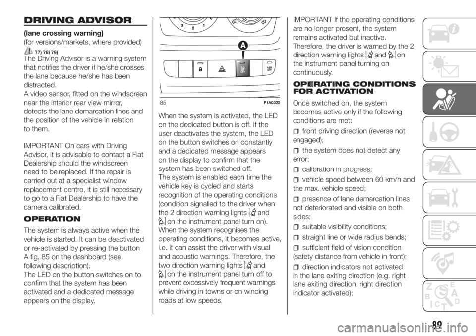
The system is always active when the
vehicle is started. It can be deactivated
or re-activated by pressing the button
A fig. 85 on the dashboard (see
following description).
The LED on the button switches on to
confirm that the system has been
activated and a dedicated message
appears on the display.When the system is activated, the LED
on the dedicated button is off. If the
user deactivates the system, the LED
on the button switches on constantly
and a dedicated message appears
on the display to confirm that the
system has been switched off.
The system is enabled each time the
vehicle key is cycled and starts
recognition of the operating conditions
(condition signalled to the driver when
the 2 direction warning lights
and
on the instrument panel turn on).
When the system recognises the
operating conditions, it becomes active,
i.e. it can assist the driver with visual
and acoustic warnings. Therefore, the
two direction warning lights
and
on the instrument panel turn off to
prevent excessively frequent warnings
while driving in towns or on winding
roads at low speeds.IMPORTANT If the operating conditions
are no longer present, the system
remains activated but inactive.
Therefore, the driver is warned by the 2
direction warning lights
andon
the instrument panel turning on
continuously.
OPERATING CONDITIONS
FOR ACTIVATION
Once switched on, the system
becomes active only if the following
conditions are met:
front driving direction (reverse not
engaged);
the system does not detect any
error;
calibration in progress;
vehicle speed between 60 km/h and
the max. vehicle speed;
presence of lane demarcation lines
not deteriorated and visible on both
sides;
suitable visibility conditions;
straight line or wide radius bends;
sufficient field of vision condition
(safety distance from vehicle in front);
direction indicators not activated
in the lane exiting direction (e.g. right
lane exiting direction, right direction
indicator activated);
85F1A0322
89
Page 117 of 296
STARTING THE
ENGINE
The vehicle is fitted with an electronic
engine lock device: if the engine fails to
start, see the paragraph “The Fiat
CODE system” in section “Know your
vehicle”.
Before starting the vehicle, adjust the
seat, the interior rear view mirrors,
the door mirrors and fasten the seat
belts correctly. Never press the
accelerator pedal for starting the
engine.
115)
14) 15)
PROCEDURE FOR
VERSIONS WITH MANUAL
TRANSMISSION
Proceed as follows:
engage the handbrake;
put the gear lever into neutral;
turn the ignition key to theMAR
position: the warning lights
and
on the instrument panel will turn on;
wait for the warning lightsand
to turn off, which will happen faster
the warmer the engine is;
fully depress the clutch pedal
without touching the accelerator;
turn the ignition key to the AVV
position as soon as the warning light
turns off. Waiting too long will waste
the heating work carried out by the
plugs.
Release the key as soon as the engine
starts.
PROCEDURE FOR
VERSIONS WITH
COMFORT MATIC
TRANSMISSION
The system allows the engine to be
started both with a gear engaged and
with the gearbox in neutral (N);
however, the brake pedal must be
pressed first with a gear engaged.
It is advisable to place the gear lever in
neutral (N) before starting the engine.
16)
PROCEDURE FOR
NATURAL POWER
VERSIONS
(For versions/markets, where provided)
The various engine cranking methods
are described below:
METHANE tank not on reserve –
petrol tank not empty:
the engine is always started in methane
mode;
METHANE tank empty – petrol tank
not empty:the engine is forced to start on petrol
and it will not switch to methane until
the methane tank has been filled. At the
same time, the reserve warning light
will turn on and the "REFUELLING
REQUIRED" message will be shown on
the instrument panel display;
METHANE tank not on reserve –
petrol tank empty:
the engine is always started in methane
mode.
17) 18) 19) 20) 21)
WARNING
115)It is dangerous to run the engine in
enclosed areas. The engine takes in
oxygen and releases carbon dioxide,
carbon monoxide and other toxic gases.
WARNING
14)It is advisable not to demand maximum
performance from your vehicle (e.g.
excessive acceleration, long distances at
high speeds, excessive intense braking,
etc.) during the initial period of use.
15)When the engine is switched off never
leave the key turned to MAR-ON to prevent
useless current absorption from draining
the battery.
115
Page 126 of 296
WARNING
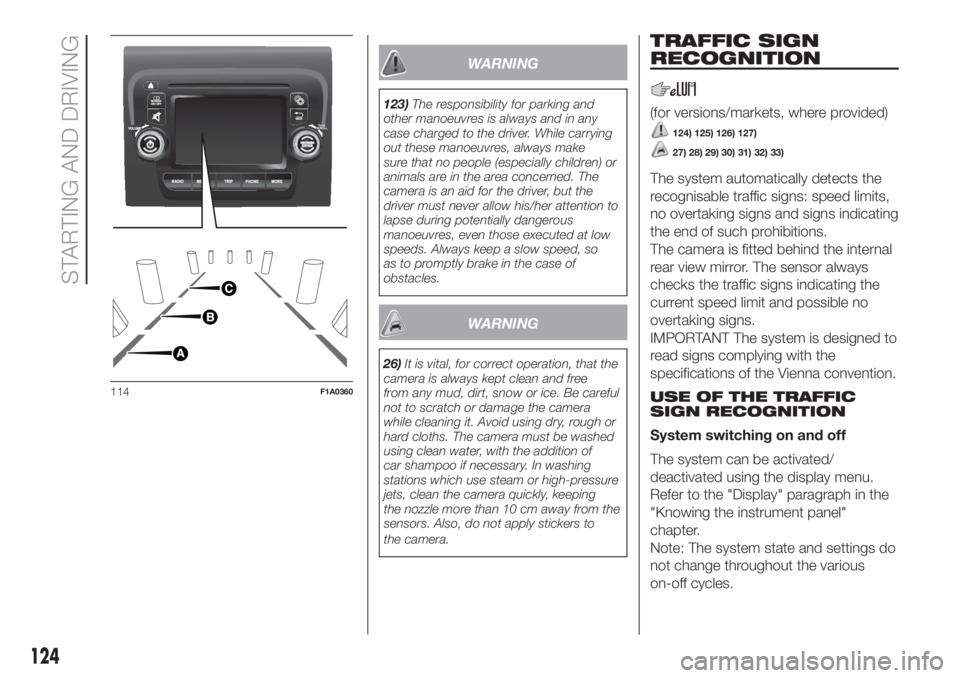
123)The responsibility for parking and
other manoeuvres is always and in any
case charged to the driver. While carrying
out these manoeuvres, always make
sure that no people (especially children) or
animals are in the area concerned. The
camera is an aid for the driver, but the
driver must never allow his/her attention to
lapse during potentially dangerous
manoeuvres, even those executed at low
speeds. Always keep a slow speed, so
as to promptly brake in the case of
obstacles.
WARNING
26)It is vital, for correct operation, that the
camera is always kept clean and free
from any mud, dirt, snow or ice. Be careful
not to scratch or damage the camera
while cleaning it. Avoid using dry, rough or
hard cloths. The camera must be washed
using clean water, with the addition of
car shampoo if necessary. In washing
stations which use steam or high-pressure
jets, clean the camera quickly, keeping
the nozzle more than 10 cm away from the
sensors. Also, do not apply stickers to
the camera.
TRAFFIC SIGN
RECOGNITION
(for versions/markets, where provided)
124) 125) 126) 127)
27) 28) 29) 30) 31) 32) 33)
The system automatically detects the
recognisable traffic signs: speed limits,
no overtaking signs and signs indicating
the end of such prohibitions.
The camera is fitted behind the internal
rear view mirror. The sensor always
checks the traffic signs indicating the
current speed limit and possible no
overtaking signs.
IMPORTANT The system is designed to
read signs complying with the
specifications of the Vienna convention.
USE OF THE TRAFFIC
SIGN RECOGNITION
System switching on and off
The system can be activated/
deactivated using the display menu.
Refer to the "Display" paragraph in the
"Knowing the instrument panel"
chapter.
Note: The system state and settings do
not change throughout the various
on-off cycles.
114F1A0360
124
STARTING AND DRIVING