open bonnet FIAT DUCATO BASE CAMPER 2017 Owner handbook (in English)
[x] Cancel search | Manufacturer: FIAT, Model Year: 2017, Model line: DUCATO BASE CAMPER, Model: FIAT DUCATO BASE CAMPER 2017Pages: 296, PDF Size: 14.44 MB
Page 13 of 296
 5)Under no circumstances should
aftermarket operations be carried out
involving steering system or steering
column modifications (e.g. installation of
anti-theft device). This could negatively
affect")
5)Under no circumstances should
aftermarket operations be carried out
involving steering system or steering
column modifications (e.g. installation of
anti-theft device). This could negatively
affect performance and safety, invalidate
the warranty, cause serious safety
problems and also result in vehicle
non-compliance with type-approval
requirements.ELECTRONIC ALARM
(for versions/markets, where provided)
The alarm, in addition to all the remote
control functions described previously,
is controlled by the receiver located
under the dashboard near the fuse box.
Activation
With the doors and bonnet closed and
the ignition key either turned to STOP
or removed, point the key with the
remote control towards the vehicle and
press and release the lock button.
Excluding some markets, the system
produces an acoustic signal (beep) and
enables door locking.
The switching on of the alarm is
preceded by an self-diagnosis stage: if
a fault is detected, the system
produces another acoustic signal.
In this case, turn the alarm off by
pressing the "release doors/release
load compartment" button, check that
the doors and bonnet are properly
closed and turn the alarm back on by
pressing the lock button.
If a door or the bonnet is not properly
shut, it will be excluded from the testing
by the alarm system.If the alarm produces an acoustic signal
even when the doors and bonnet are
correctly closed, a fault has occurred in
the operation of the system. Contact
a Fiat Dealership.
IMPORTANT The alarm does not come
on when the central locking is activated
using the metal insert in the key.
IMPORTANT The alarm is adapted to
meet requirements in various countries.
Turning off
Press the door release/load
compartment release button on the key
with remote control.
The following operations are performed
(excluding some markets):
direction indicators flash twice;
there are two short acoustic signals
(beeps);
doors are unlocked.
IMPORTANT The alarm does not switch
off when the central opening is
activated using the metal insert in the
key.
11
Page 44 of 296
 IMPORTANT With the ignition key in the
STOP position or extracted, the
electric windows remain activated for
about 3 minutes and are deactivated
immediately when one of the doors
is opened.
Front pass")
IMPORTANT With the ignition key in the
STOP position or extracted, the
electric windows remain activated for
about 3 minutes and are deactivated
immediately when one of the doors
is opened.
Front passenger side door
A dedicated switch for operating the
window is located on the inner armrest
of the passenger side front door.
35)
WARNING
35)Incorrect use of the electric windows
may be dangerous. Before and during
operation, always check that nobody
is exposed to the risk of being injured
either directly by the moving window or
through objects getting caught or by being
hit. When leaving the vehicle, always
remove the key from the ignition switch to
avoid the risk of injury to anyone remaining
in the car due to accidental operation of
the electric windows.
BONNET
OPENING
Proceed as follows:
open the driver's door to gain
access to the bonnet release handle;
pull the lever fig. 67 in the direction
indicated by the arrow;
lift lever A fig. 68 as shown in the
figure;
lift the bonnet and, at the same time,
release the bonnet stay fig. 69 from its
locking device D, then insert the end
C fig. 70 of the bonnet stay into the
housing E.
IMPORTANT Before opening the
bonnet, check that the windscreen
wiper arms are not lifted from the
windscreen.CLOSING
Proceed as follows:
hold the bonnet up with one hand
and with the other remove the stay
C fig. 70 from the housing E and fit it
back in its locking device D fig. 69;
lower the bonnet to approximately
20 centimetres from the engine
compartment and let it drop. Make sure
that the bonnet is completely closed
and not only fastened by the locking
device by trying to open it. If it is not
perfectly closed, do not try to press the
bonnet down but open it and repeat
the procedure.
67F1A0126
68F1A0339
42
KNOWING YOUR VEHICLE
Page 45 of 296
 IMPORTANT Always check that the
bonnet is closed correctly to prevent it
from opening while the vehicle is
travelling.
36) 37) 38)
WARNING
36)For safety reasons, the bonnet must
always be perfectly cl")
IMPORTANT Always check that the
bonnet is closed correctly to prevent it
from opening while the vehicle is
travelling.
36) 37) 38)
WARNING
36)For safety reasons, the bonnet must
always be perfectly closed while travelling.
Make sure that the bonnet is perfectly
closed and that the lock is engaged. If you
notice when driving that the bonnet has
not been properly locked, stop immediately
and close the bonnet correctly.
37)Incorrect positioning of the stay rod
may cause the bonnet to drop suddenly.
38)Perform these operations only when
the vehicle is stationary.
HEAD RESTRAINTS
FRONT
On certain versions the head restraints
are adjustable in height and they lock
automatically in the required position.
39)
Adjustment
Upward adjustment: lift the head
restraint until it clicks into place.
Downwards adjustment: press the
button A fig. 71 and lower the head
restraint.
To extract the front head restraints
press buttons A and B fig. 71 at the
sides of the two supports
simultaneously and release them
upwards.
69F1A0349
70F1A0129
71F1A0039
43
Page 148 of 296
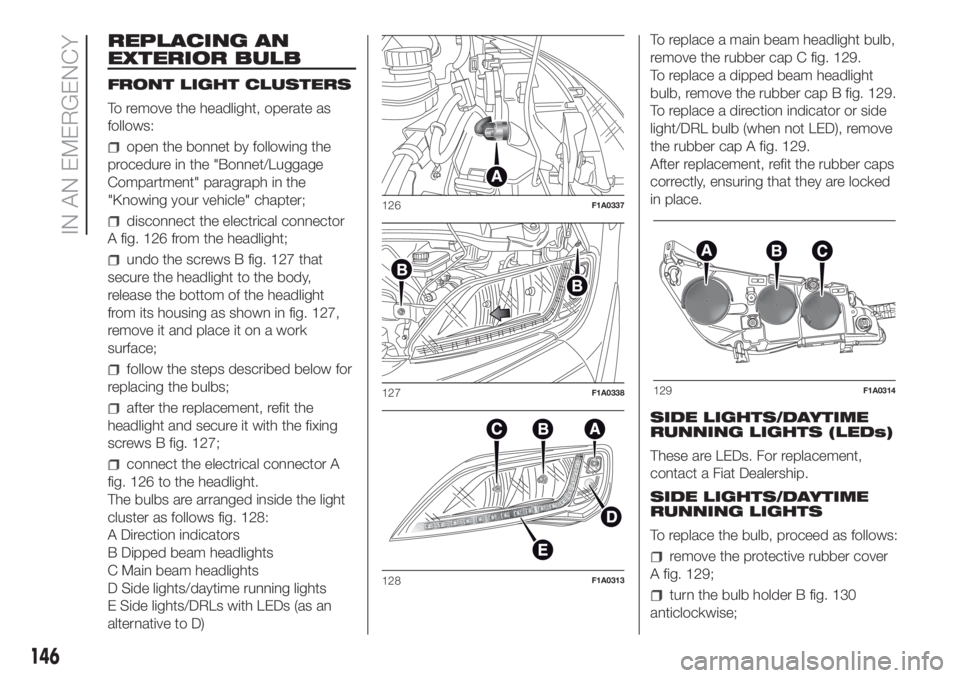
REPLACING AN
EXTERIOR BULB
FRONT LIGHT CLUSTERS
To remove the headlight, operate as
follows:
open the bonnet by following the
procedure in the "Bonnet/Luggage
Compartment" paragraph in the
"Knowing your vehicle" chapter;
disconnect the electrical connector
A fig. 126 from the headlight;
undo the screws B fig. 127 that
secure the headlight to the body,
release the bottom of the headlight
from its housing as shown in fig. 127,
remove it and place it on a work
surface;
follow the steps described below for
replacing the bulbs;
after the replacement, refit the
headlight and secure it with the fixing
screws B fig. 127;
connect the electrical connector A
fig. 126 to the headlight.
The bulbs are arranged inside the light
cluster as follows fig. 128:
A Direction indicators
B Dipped beam headlights
C Main beam headlights
D Side lights/daytime running lights
E Side lights/DRLs with LEDs (as an
alternative to D)To replace a main beam headlight bulb,
remove the rubber cap C fig. 129.
To replace a dipped beam headlight
bulb, remove the rubber cap B fig. 129.
To replace a direction indicator or side
light/DRL bulb (when not LED), remove
the rubber cap A fig. 129.
After replacement, refit the rubber caps
correctly, ensuring that they are locked
in place.
SIDE LIGHTS/DAYTIME
RUNNING LIGHTS (LEDs)
These are LEDs. For replacement,
contact a Fiat Dealership.
SIDE LIGHTS/DAYTIME
RUNNING LIGHTS
To replace the bulb, proceed as follows:
remove the protective rubber cover
A fig. 129;
turn the bulb holder B fig. 130
anticlockwise;
126F1A0337
127F1A0338
128F1A0313
129F1A0314
146
IN AN EMERGENCY