torque FIAT DUCATO BASE CAMPER 2017 Owner handbook (in English)
[x] Cancel search | Manufacturer: FIAT, Model Year: 2017, Model line: DUCATO BASE CAMPER, Model: FIAT DUCATO BASE CAMPER 2017Pages: 296, PDF Size: 14.44 MB
Page 83 of 296
ABS SYSTEM
This is an integral part of the braking
system, which prevents one or more
wheels from locking and slipping
regardless of the road surface
conditions and braking intensity,
ensuring control of the vehicle even
during emergency braking.
The system intervenes during braking
when the wheels are about to lock,
typically in emergency braking or
low-grip conditions, when locking may
be more frequent.
The ABS ensures the direction of the
vehicle while braking and optimises the
braking distances at the same time.
The system also improves control and
stability of the vehicle when braking
on a surface on which the grip of the
left and right wheels differs, or when
braking while cornering.
The system is completed by EBD
(Electronic Braking Force Distribution),
which distributes the braking action
between the front and rear wheels.
IMPORTANT For maximum efficiency of
the braking system, a bedding-in
period of about 500 km is needed:
during this period it is better to avoid
sharp, repeated and prolonged braking.
49)
SYSTEM INTERVENTION
The driver can feel that the ABS has
come into action because the brake
pedal pulsates slightly and the system
gets noisier: it means that the vehicle
speed should be altered to suit the type
of road surface.
50) 51) 52) 53) 54) 55) 56)
MSR SYSTEM
(Motor Schleppmoment Regelung)
This is an integral part of the ABS
system and prevents the drive wheels
from locking, which could happen,
for example, if the accelerator pedal is
released suddenly or in the case of
shifting down suddenly in conditions of
poor grip. In these conditions, the
engine braking effect could cause the
drive wheels to slip, resulting in a loss
of vehicle stability. In these situations,
the system intervenes, restoring torque
to the engine in order to conserve
vehicle stability and increase safety.
WARNING
49)The ABS gets the most from the
available grip, but it cannot improve it; you
should therefore take every care when
driving on slippery surfaces and not take
unnecessary risks.50)When the ABS cuts in and you feel the
brake pedal pulsating, do not remove
your foot, but keep the pedal pushed
down; in doing so you, will stop in the
shortest distance possible under the road
conditions at the time.
51)If the ABS system intervenes, this
indicates that the traction of the tyres on
the road is nearing its limit. You must slow
down to a speed compatible with the
available traction.
52)The ABS cannot overrule the natural
laws of physics, and cannot increase
the grip available according to the
condition of the road.
53)The ABS system cannot prevent
accidents, including those due to excessive
speed on corners, driving on low-grip
surfaces or aquaplaning.
54)The capability of the ABS must never
be tested irresponsibly and dangerously, in
such a way as to compromise personal
safety and the safety of others.
55)For the correct operation of the ABS,
the tyres must of necessity be the same
make and type on all wheels, in perfect
condition and, above all, of the prescribed
type and dimensions.
56)If the space-saver wheel (for
versions/markets, where provided) is used,
the ABS keeps operating. Always
remember that the space-saver wheel,
being smaller than the original wheel,
provides less grip.
81
Page 84 of 296
ESC (Electronic
Stability Control)
SYSTEM
(for versions/markets, where provided)
The ESC system improves the
directional control and stability of the
vehicle in various driving conditions.
The ESC system corrects the vehicle’s
understeer and oversteer, distributing
the brake force on the appropriate
wheels. The torque supplied by the
engine can also be reduced in order to
maintain control of the vehicle.
The ESC system uses the sensors in
the vehicle to determine the trajectory
required by the driver through steering
and compares it with the real trajectory
of the vehicle. When the real trajectory
deviates from the desired trajectory, the
ESC system intervenes to counter the
car’s understeer or oversteer.
Oversteer: occurs when the vehicle
is turning more than it should according
to the angle of the steering wheel.
Understeer: occurs when the vehicle
is turning less than it should according
to the angle of the steering wheel.The ESC system also includes the
following subsystems:
Hill Holder
ASR
HBA
ERM
HDC
57) 58) 59)
SYSTEM INTERVENTION
This is signalled by the flashing of the
warning light in the instrument panel,
to inform the driver that the vehicle is
in critical stability and grip conditions.
SYSTEM ACTIVATION
The ESC system switches on
automatically when the engine is
started and cannot be switched off.
HILL HOLDER SYSTEM
This system is an integral part of the
ESC system and facilitates starting on
slopes.
It is automatically activated in the
following conditions:
uphill: vehicle stationary on a road
with a gradient higher than 5%, engine
running, brake pressed and gearbox
in neutral or gear (other than reverse)
engaged;
downhill: vehicle stationary on a road
with a gradient higher than 5%, engine
running, brake pressed and reverse
gear engaged.
When setting off, the ESC system
control unit maintains the braking
pressure on the wheels until the torque
necessary for starting is reached, or
in any case for a maximum of 2
seconds, allowing your right foot to be
moved easily from the brake pedal to
the accelerator.
When two seconds have elapsed,
without starting, the system is
automatically deactivated, gradually
releasing the braking pressure. During
this release stage, the typical brake
disengagement noise indicating that the
vehicle is going to move imminently
will be heard.
IMPORTANT The Hill Holder system is
not a parking brake; therefore, never
leave the vehicle without having
engaged the handbrake, turned the
engine off and engaged first gear,
so that it is parked in safe conditions
(for further information read the
"Parking" paragraph in the "Starting
and driving" chapter).
82
SAFETY
Page 87 of 296
64)The HBA system is an aid for the driver,
who must always pay full attention while
driving. The responsibility always rests with
the driver. The features of the HBA system
must never be tested in imprudent or
dangerous ways, with the possibility of
putting the safety of the driver, occupants
or other road users at risk.
65)The performance of a vehicle with
ERM must never be tested in imprudent or
dangerous ways, with the possibility of
putting the safety of the driver or other
people at risk.
WARNING
12)Prolonged use of the system may
overheat the braking system. If the brakes
overheat, the HDC system, when active,
will be gradually deactivated after suitably
informing the driver (the LED on the button
turns off): it can be reactivated only when
the brakes have cooled sufficiently. The
distance you can travel depends on the
brake temperature and thus on the slope,
the load and the vehicle speed.
TRACTION PLUS
SYSTEM
(for versions/markets, where provided)
Traction Plus is a driving aid, useful
for setting off in poor grip conditions on
non-homogeneous road surfaces
(snow/asphalt, ice/asphalt, mud/
asphalt, etc.), which allows the drive
force to be distributed adequately
on the engine axle when one of the two
drive wheels slips.
Traction Plus acts by braking the wheel
with poor grip (or slipping more than
the others), thereby transferring the
drive force to that which has greater
grip on the ground.
This function can be activated manually
by pressing button A on the dashboard
fig. 84 and operates under 50 km/h.
When this speed is exceeded, it is
automatically deactivated (the LED on
the button is still on) and it is
reactivated again when the speed falls
below 30 km/h.
66) 67)
Traction Plus operation
The system is deactivated when
starting. To activate the Traction Plus
system, press button A fig. 84: the LED
on the button switches on.The activation of the Traction Plus
system involves the following functions
being switched on:
inhibition of the ASR function, in
order to fully exploit the engine torque;
the differential locking effect on
the front axle, through the braking
system, to improve traction on irregular
grounds.
If the Traction Plus system is faulty, the
warning light on the instrument
panel switches on constantly.
When travelling on snowy roads with
snow chains, it may be helpful to turn
the Traction Plus on and thus inhibiting
the ASR function: in fact, in these
conditions, slipping of the drive wheels
when moving off makes it possible to
obtain better traction.
84F1A0325
85
Page 88 of 296
WARNING
66)The Traction Plus system acts
effectively only on road surfaces that are
not homogeneous and/or differentiated
between the two drive wheels.
67)Until the setting off manoeuvre is
terminated, fully depress the accelerator
pedal in order to transfer all the drive
torque to the wheel with the best grip.
TPMS (Tyre
Pressure
Monitoring System)
(for versions/markets, where provided)
68) 69) 70) 71) 72) 73) 74) 75) 76)
DESCRIPTION
The tyre pressure monitoring system
(TPMS) warns the driver of low tyre
pressure on the basis of the cold
inflation pressure prescribed for the
vehicle.
Changes in outside temperature may
cause tyre pressure to vary. This means
that a decrease in the outside
temperature corresponds to a decrease
in the tyre pressure.
Tyre pressure must always be adjusted
according to the cold inflation pressure.
Cold tyre inflation pressure is the tyre
pressure after letting the vehicle stand
for at least three hours or a travel
shorter than 1.6 km after an interval of
three hours.
The cold tyre inflation pressure must
not exceed the maximum inflation
pressure value printed on the side of
the tyre.
The tyre pressure also increases while
driving the vehicle: this is a normal
condition and does not require any
adjustment of the pressure.The TPMS continues to advise the
driver of the low tyre pressure condition
until this is corrected; the warning
continues until the pressure
corresponds or exceeds the pressure
prescribed for the cold tyres. When the
low tyre pressure check warning light
turns on continuously, the inflation
pressure must be adjusted until it
reaches the pressure prescribed for
cold tyres. After the automatic update
of the system, the tyre pressure control
warning light switches off. You may
need to drive the vehicle for about 20
minutes at a speed higher than 20
km/h to allow the TPMS to receive this
information.
NOTE
The TPMS does not replace the
normal tyre maintenance service and
does not indicate any fault in a tyre.
Therefore, the TPMS should not be
used as pressure switch while adjusting
the tyre inflation pressure.
Driving with insufficient tyre pressure
causes their overheating and can
result in tyre failure. The low inflation
pressure reduces fuel efficiency and
tyre tread life and may also affect
handling and braking performance of
the vehicle.
86
SAFETY
Page 120 of 296
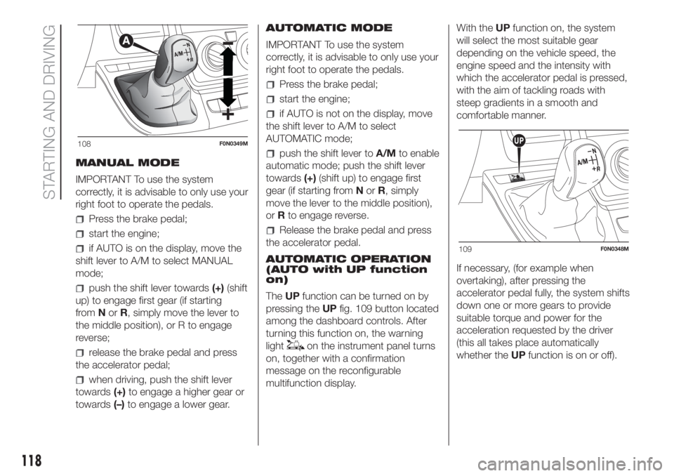
MANUAL MODE
IMPORTANT To use the system
correctly, it is advisable to only use your
right foot to operate the pedals.
Press the brake pedal;
start the engine;
if AUTO is on the display, move the
shift lever to A/M to select MANUAL
mode;
push the shift lever towards(+)(shift
up) to engage first gear (if starting
fromNorR, simply move the lever to
the middle position), or R to engage
reverse;
release the brake pedal and press
the accelerator pedal;
when driving, push the shift lever
towards(+)to engage a higher gear or
towards(–)to engage a lower gear.AUTOMATIC MODE
IMPORTANT To use the system
correctly, it is advisable to only use your
right foot to operate the pedals.
Press the brake pedal;
start the engine;
if AUTO is not on the display, move
the shift lever to A/M to select
AUTOMATIC mode;
push the shift lever toA/Mto enable
automatic mode; push the shift lever
towards(+)(shift up) to engage first
gear (if starting fromNorR, simply
move the lever to the middle position),
orRto engage reverse.
Release the brake pedal and press
the accelerator pedal.
AUTOMATIC OPERATION
(AUTO with UP function
on)
TheUPfunction can be turned on by
pressing theUPfig. 109 button located
among the dashboard controls. After
turning this function on, the warning
light
on the instrument panel turns
on, together with a confirmation
message on the reconfigurable
multifunction display.With theUPfunction on, the system
will select the most suitable gear
depending on the vehicle speed, the
engine speed and the intensity with
which the accelerator pedal is pressed,
with the aim of tackling roads with
steep gradients in a smooth and
comfortable manner.
If necessary, (for example when
overtaking), after pressing the
accelerator pedal fully, the system shifts
down one or more gears to provide
suitable torque and power for the
acceleration requested by the driver
(this all takes place automatically
whether theUPfunction is on or off).
108F0N0349M
109F0N0348M
118
STARTING AND DRIVING
Page 133 of 296
These two systems ensure compliance
with the diesel emissions requirements;
at the same it maintains fuel saving
levels, driveability, torque and power.
For the system messages and warnings
refer to the "Warning lights and
messages" paragraph in the "Knowing
the instrument panel" section.
Notes
When you stop the vehicle you
could hear a distinct click coming from
under the vehicle due to the UREA
injection system, this is normal.
The UREA injection system pump
continues to operate for a short period
of time after the engine is switched
off, to purge the circuit. This is normal,
and you can still hear its noise from
under the vehicle.
VERSION WITH
METHANE SYSTEM
(Natural Power)
37) 38)
INTRODUCTION
The "Natural Power" version of the Fiat
Ducato features two fuel system, one
primary natural gas (methane) system
and one emergency petrol system.
METHANE CYLINDERS
The vehicle is equipped with five
cylinders (total capacity of about 218
litres) located under the vehicle floor
and protected by two special shields.
The cylinders are the tank that contains
the methane in its compressed
gaseous state (nominal pressure of 200
bar at 15°C). The methane, stored in
the cylinders at high pressure, flows
through a dedicated pipe to reach the
pressure regulator/reduction unit which
supplies the 4 methane injectors at
low pressure (about 6 bar).
IMPORTANT If gas is smelled, switch
from methane operation to petrol
operation and immediately go to a Fiat
Dealership to have the vehicle checked
and possible system faults excluded.FUEL SWITCHING
LOGICS
Management of switching between the
two different fuel supplies is fully
automatic, and carried out by the
engine control unit.
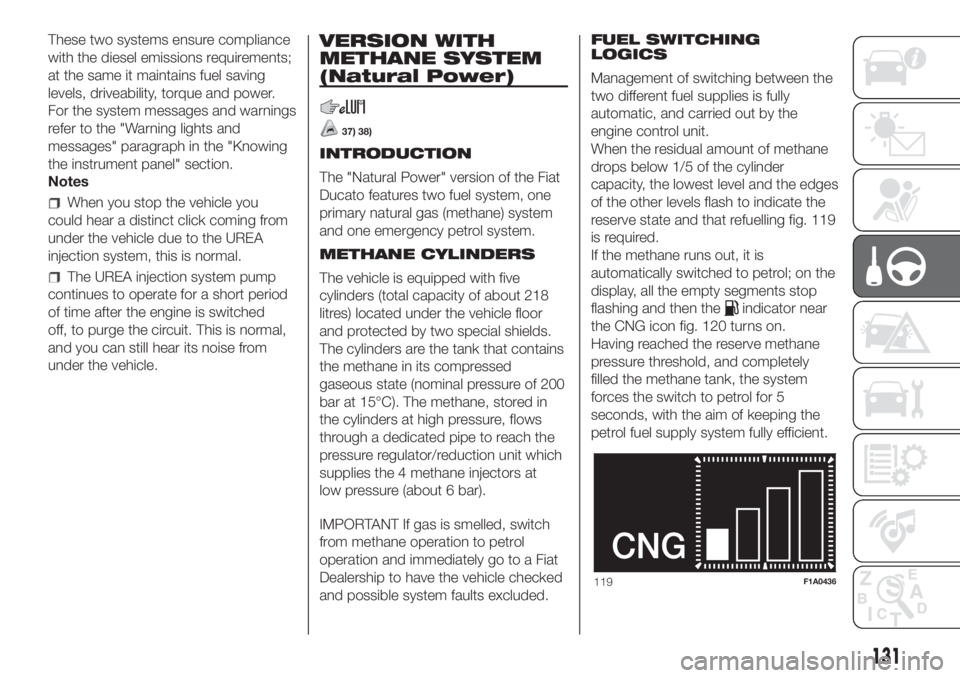
When the residual amount of methane
drops below 1/5 of the cylinder
capacity, the lowest level and the edges
of the other levels flash to indicate the
reserve state and that refuelling fig. 119
is required.
If the methane runs out, it is
automatically switched to petrol; on the
display, all the empty segments stop
flashing and then the
indicator near
the CNG icon fig. 120 turns on.
Having reached the reserve methane
pressure threshold, and completely
filled the methane tank, the system
forces the switch to petrol for 5
seconds, with the aim of keeping the
petrol fuel supply system fully efficient.
119F1A0436
131
Page 168 of 296
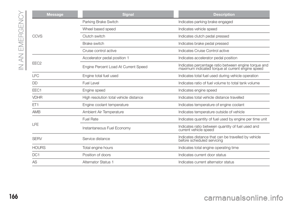
Message Signal Description
CCVSParking Brake Switch Indicates parking brake engaged
Wheel based speed Indicates vehicle speed
Clutch switch Indicates clutch pedal pressed
Brake switch Indicates brake pedal pressed
Cruise control active Indicates Cruise Control active
EEC2Accelerator pedal position 1 Indicates accelerator pedal position
Engine Percent Load At Current SpeedIndicates percentage ratio between engine torque and
maximum indicated torque at current engine speed
LFC Engine total fuel used Indicates total fuel used during vehicle operation
DD Fuel Level Indicates ratio of fuel volume to total tank volume
EEC1 Engine speed Indicates engine speed
VDHR High resolution total vehicle distance Indicates total vehicle distance travelled
ET1 Engine coolant temperature Indicates temperature of engine coolant
AMB Ambient Air Temperature Indicates temperature outside of vehicle
LFEFuel Rate Indicates quantity of fuel used by engine per time unit
Instantaneous Fuel EconomyIndicates ratio between quantity of fuel used and
current vehicle speed
SERV Service distanceIndicates distance that can be travelled by vehicle
before scheduled servicing
HOURS Total engine hours Indicates total engine operating time
DC1 Position of doors Indicates current door status
AS Alternator Status 1 Indicates current alternator status
166
IN AN EMERGENCY
Page 193 of 296
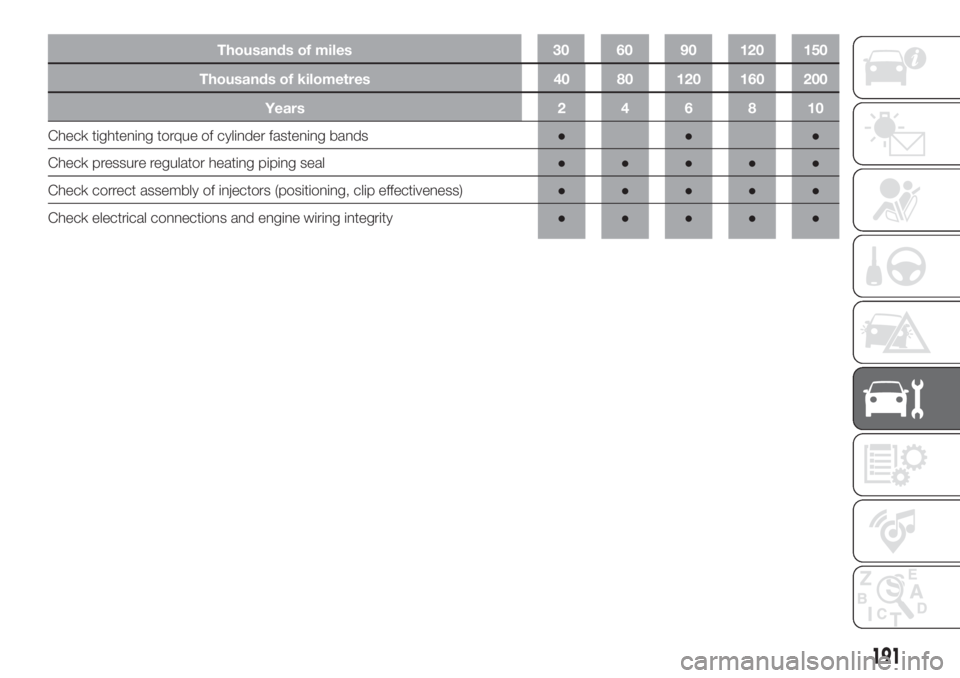
Thousands of kilometres 40 80 120 160 200
Years246810
Check tightening torque of cylinder fastening bands●●●
Check pressure regulator heating piping seal●●●●●
Check correct assembly of injectors (positioning, clip effectiveness)●●●●●
Check electrical connections and engine wiring integrity●●●●●
191
Thousands of miles 30 60 90 120 150
Page 215 of 296
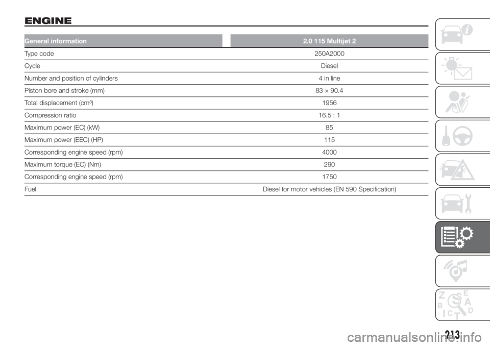
ENGINE
General information2.0 115 Multijet 2
Type code250A2000
CycleDiesel
Number and position of cylinders 4 in line
Piston bore and stroke (mm)83 × 90.4
Total displacement (cm³)1956
Compression ratio16.5 : 1
Maximum power (EC) (kW)85
Maximum power (EEC) (HP)115
Corresponding engine speed (rpm) 4000
Maximum torque (EC) (Nm)290
Corresponding engine speed (rpm) 1750
FuelDiesel for motor vehicles (EN 590 Specification)
213
Page 216 of 296
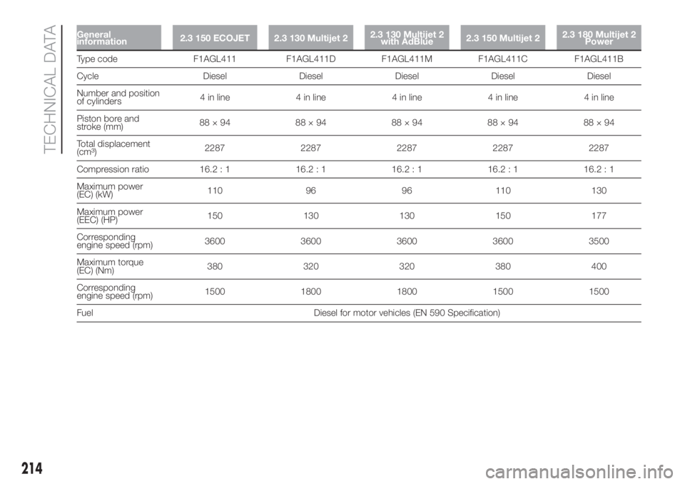
General
information2.3 150 ECOJET 2.3 130 Multijet 22.3 130 Multijet 2
with AdBlue2.3 150 Multijet 22.3 180 Multijet 2
Power
Type code F1AGL411 F1AGL411D F1AGL411M F1AGL411C F1AGL411B
Cycle Diesel Diesel Diesel Diesel Diesel
Number and position
of cylinders4 in line 4 in line 4 in line 4 in line 4 in line
Piston bore and
stroke (mm)88×94 88×94 88×94 88×94 88×94
Total displacement
(cm³)2287 2287 2287 2287 2287
Compression ratio 16.2 : 1 16.2 : 1 16.2 : 1 16.2 : 1 16.2 : 1
Maximum power
(EC) (kW)110 96 96 110 130
Maximum power
(EEC) (HP)150 130 130 150 177
Corresponding
engine speed (rpm)3600 3600 3600 3600 3500
Maximum torque
(EC) (Nm)380 320 320 380 400
Corresponding
engine speed (rpm)1500 1800 1800 1500 1500
Fuel Diesel for motor vehicles (EN 590 Specification)
214
TECHNICAL DATA