wheel size FIAT DUCATO BASE CAMPER 2017 Owner handbook (in English)
[x] Cancel search | Manufacturer: FIAT, Model Year: 2017, Model line: DUCATO BASE CAMPER, Model: FIAT DUCATO BASE CAMPER 2017Pages: 296, PDF Size: 14.44 MB
Page 86 of 296

HILL DESCENT CONTROL
(HDC) SYSTEM
It is an integral part of the ESC and is
aimed at keeping the vehicle at a
constant speed during a descent,
operating autonomously on the brakes
in various ways at the same time. In this
way the vehicle stability and completely
safe driving are guaranteed, above all
in poor grip conditions and/or steep
descents.
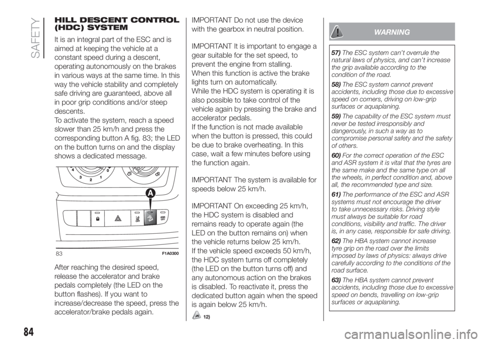
To activate the system, reach a speed
slower than 25 km/h and press the
corresponding button A fig. 83; the LED
on the button turns on and the display
shows a dedicated message.
After reaching the desired speed,
release the accelerator and brake
pedals completely (the LED on the
button flashes). If you want to
increase/decrease the speed, press the
accelerator/brake pedals again.IMPORTANT Do not use the device
with the gearbox in neutral position.
IMPORTANT It is important to engage a
gear suitable for the set speed, to
prevent the engine from stalling.
When this function is active the brake
lights turn on automatically.
While the HDC system is operating it is
also possible to take control of the
vehicle again by pressing the brake and
accelerator pedals.
If the function is not made available
when the button is pressed, this could
be due to brake overheating. In this
case, wait a few minutes before using
the function again.
IMPORTANT The system is available for
speeds below 25 km/h.
IMPORTANT On exceeding 25 km/h,
the HDC system is disabled and
remains ready to operate again (the
LED on the button remains on) when
the vehicle returns below 25 km/h.
If the vehicle speed exceeds 50 km/h,
the HDC system turns off completely
(the LED on the button turns off) and
any autonomous action on the brakes
is disabled. To reactivate it, press the
dedicated button again when the speed
is again below 25 km/h.
12)
WARNING
57)The ESC system can’t overrule the
natural laws of physics, and can’t increase
the grip available according to the
condition of the road.
58)The ESC system cannot prevent
accidents, including those due to excessive
speed on corners, driving on low-grip
surfaces or aquaplaning.
59)The capability of the ESC system must
never be tested irresponsibly and
dangerously, in such a way as to
compromise personal safety and the safety
of others.
60)For the correct operation of the ESC
and ASR system it is vital that the tyres are
the same make and the same type on all
the wheels, in perfect condition and, above
all, the recommended type and size.
61)The performance of the ESC and ASR
systems must not encourage the driver
to take unnecessary risks. Driving style
must always be suitable for road
conditions, visibility and traffic. The driver
is, in any case, responsible for safe driving.
62)The HBA system cannot increase
tyre grip on the road over the limits
imposed by laws of physics: always drive
carefully according to the conditions of the
road surface.
63)The HBA system cannot prevent
accidents, including those due to excessive
speed on bends, travelling on low-grip
surfaces or aquaplaning.
83F1A0300
84
SAFETY
Page 90 of 296

WARNING
68)The TPMS is optimised for the original
tyres and wheels provided. TPMS
pressures and alerts have been defined
according to the size of the tyres mounted
on the vehicle. Using equipment with
different size, type or kind may cause
irregular system operation or sensor
damage. Non-original spare wheels can
damage the sensor. Do not use tyre
sealant or balancing weights if the vehicle
is equipped with TPMS as these may
damage the sensors.
69)If the system signals a pressure
decrease on a specific tyre, it is
recommended to check the pressure on all
four tyres.
70)The TPMS does not relieve the driver
from the obligation to check the tyre
pressure every month; it is not even to be
considered a replacing system for
maintenance or a safety system.
71)Tyre pressure must be checked with
tyres cold. Should it become necessary for
whatever reason to check pressure with
warm tyres, do not reduce pressure even
though it is higher than the prescribed
value, but repeat the check when tyres are
cold.
72)The TPMS cannot indicate sudden tyre
pressure drops (for example when a tyre
bursts). In this case, stop the vehicle,
braking with caution and avoiding abrupt
steering.73)The system only warns that the tyre
pressure is low: it is not able to inflate
them.
74)Insufficient tyre inflation increases fuel
consumption, reduces the tread duration
and may affect your ability to drive the
vehicle safely.
75)Always refit the valve stem cap after
inspecting or adjusting tyre pressure. This
prevents dampness or dirt from entering
the valve stem and thus the pressure
control sensor from being damaged.
76)The tyre repair kit (Fix&Go) provided
with the vehicle (for versions/markets,
where provided) is compatible with the
TPMS sensors; using sealants not
equivalent with that in the original kit may
adversely affect its operation. If sealants
not equivalent with the original one are
used, it is recommended to have the
TPMS sensors checked by a qualified
repair centre.
88
SAFETY
Page 174 of 296

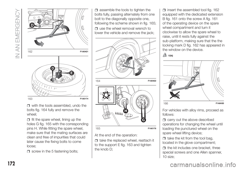
with the tools assembled, undo the
bolts fig. 164 fully and remove the
wheel;
fit the spare wheel, lining up the
holes G fig. 165 with the corresponding
pins H. While fitting the spare wheel,
make sure that the mating surfaces are
clean and free of impurities that could
later cause the fixing bolts to come
loose;
screw in the 5 fastening bolts;
assemble the tools to tighten the
bolts fully, passing alternately from one
bolt to the diagonally opposite one,
following the scheme shown in fig. 165;
use the wheel removal wrench to
lower the vehicle and remove the jack;
At the end of the operation:
take the replaced wheel, reattach it
to the support E fig. 163 and tighten
the knob D;
insert the assembled tool fig. 162
equipped with the dedicated extension
B fig. 161 onto the screw A fig. 161
of the operating device on the spare
wheel compartment and turn it
clockwise to allow the spare wheel to
raise, until it rests fully against the
sub-platform, making sure that the the
locking mark D fig. 162 has appeared in
the window on the device.
154)
For vehicles with alloy rims, proceed as
follows:
carry out the above described
operations for changing the wheel until
loading the punctured wheel on the
spare wheel lifting device;
take the kit from the tool bag,
located in the glove compartment;
the kit includes one bracket, three
special screws and one Allen spanner,
10 size;
162F1A0421
163F1A0174
164F1A0422
G
H
165F1A0176
166F1A0430
172
IN AN EMERGENCY